Understanding PCB Boards: A Comprehensive Guide
In today's technology-driven world, printed circuit boards (PCBs) are the unsung heroes that power nearly every electronic device we use, from smartphones to complex industrial machinery. These seemingly simple boards are the foundation upon which electronic components are interconnected and function. This article delves into the intricacies of PCB boards, exploring their significance, design, and various applications.
What is a PCB Board?
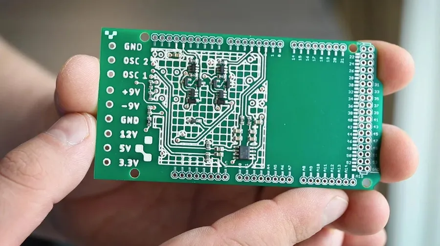
A Printed Circuit Board (PCB) serves as the foundational platform for electronic devices, acting as a non-conductive base upon which conductive pathways, or traces, are etched to connect electronic components. This structure provides both the mechanical support and the electrical connections necessary for the operation of electronic circuits.
A detailed comparison of various PCB types is essential for selecting the most suitable option for a specific application. This section provides a structured analysis of single-sided, double-sided, multi-layer, flexible, rigid-flex, and metal core PCBs, highlighting their respective advantages, disadvantages, and typical applications.
| PCB Type | Advantages | Disadvantages | Typical Applications |
|---|---|---|---|
| Single-Sided | Simple design, low cost, easy to manufacture | Limited routing, lower component density | Simple electronics, toys, basic lighting |
| Double-Sided | Increased routing flexibility, higher component density than single-sided | More complex than single-sided, higher cost | Consumer electronics, basic industrial controls |
| Multi-Layer | High component density, complex routing possible, signal integrity | Higher cost, more complex manufacturing process | Computers, high-speed communication, medical devices |
| Flexible | Flexible, lightweight, can fit in unique shapes, reliable connections in dynamic systems | More expensive, more challenging to assemble than rigid boards, less heat dissipation | Wearable technology, camera modules, automotive electronics, dynamic applications |
| Rigid-Flex | Combines benefits of rigid and flexible boards, design flexibility and space saving | Higher cost, complex design and manufacturing | Aerospace, military applications, medical devices, where the flex part is used to connect multiple rigid parts |
| Metal Core | Excellent heat dissipation, good thermal conductivity, good mechanical strength | Higher cost, heavier, more complex than FR-4 based boards | High-power LEDs, automotive applications, power electronics |
Key Components of a PCB Board
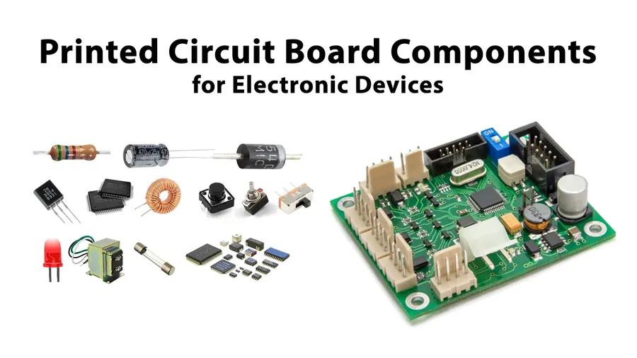
Printed Circuit Boards (PCBs) are intricate assemblies, comprising several key components that work in concert to provide electrical connectivity and mechanical support for electronic devices. Understanding these components is crucial for anyone involved in electronics design, manufacturing, or repair.
- Substrate
The substrate forms the base of the PCB, providing structural integrity and electrical insulation. Commonly made from fiberglass-reinforced epoxy (FR-4), it's a non-conductive material upon which the other layers are built. The selection of substrate material depends on the electrical and thermal performance requirements of the application, with materials like polyimide used in high-temperature applications. - Copper Traces
Copper traces are conductive pathways etched onto the substrate, forming the circuits that carry electrical signals. These thin copper strips connect various components and allow current to flow between them. Trace width and thickness are crucial for impedance control and current carrying capacity. The design of these traces is fundamental to PCB functionality. - Solder Mask
A protective layer of polymer material, the solder mask covers the majority of the PCB surface, preventing solder bridges during assembly. It's typically green, though other colors are available, and exposes only the areas where components are meant to be soldered. This prevents accidental shorts and ensures reliable electrical connections. - Silkscreen
The silkscreen is a layer of ink printed onto the PCB surface, typically used to add component designators, manufacturer logos, and test points. It's a crucial reference layer during assembly, repair, and debugging, and facilitates quick identification of components and circuit locations. It doesn't conduct electricity. - Pads
Pads are small, exposed copper areas where electronic components are soldered to the PCB. They are typically circular or rectangular in shape and come in various sizes and forms to accommodate different component packages. Correct pad design is crucial for reliable solder joints. They represent the electrical connection points between the components and the copper traces. - Vias
Vias are plated-through holes that connect different layers of the PCB, allowing electrical signals to travel vertically through the board. They come in various types (through-hole, blind, buried) depending on the design requirements and the board’s layer count. Vias are essential in multilayer boards for routing traces and distributing power.
Types of PCB Boards
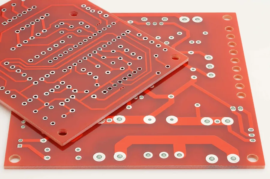
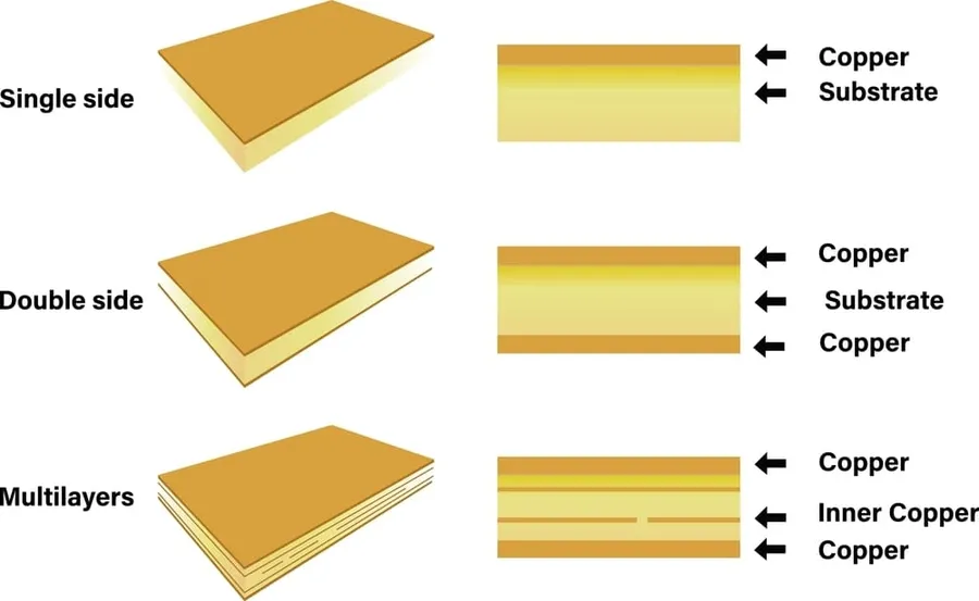
Printed circuit boards (PCBs) are not monolithic; they are manufactured in a variety of types, each tailored to specific applications and performance requirements. Understanding these differences is crucial for effective design and implementation of electronic systems. This section details the common types of PCB boards, including their characteristics and typical uses.
| PCB Type | Description | Advantages | Disadvantages | Typical Applications |
|---|---|---|---|---|
| Single-Sided | Copper layer on one side of the substrate. | Simple design, low cost, easy to manufacture. | Limited component density, less functionality. | Simple electronics, low-density circuits, toys, simple LED displays |
| Double-Sided | Copper layers on both sides of the substrate with vias connecting the layers. | Increased component density, more complex circuits compared to single-sided. | Higher cost than single-sided boards. | Consumer electronics, small power supplies, basic control systems |
| Multi-Layered | Three or more layers of copper and substrate, interconnected with vias. | High circuit density, high-speed performance, complex functionality. | High manufacturing cost, complex design and fabrication process. | High performance computers, high-end telecommunication systems, complex industrial controls, medical devices, aerospace electronics |
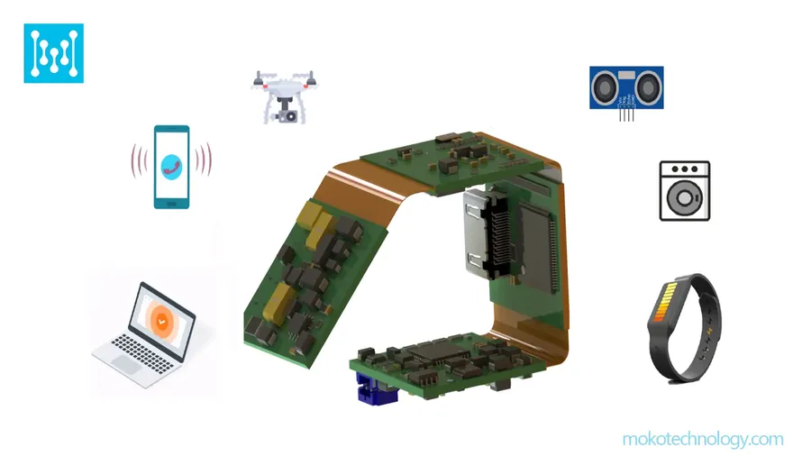
| Flexible (Flex) | Thin, flexible substrate material, allows for bending and shaping the board. | Dynamic flexing, space saving, lightweight, can conform to various shapes. | Higher cost, more delicate than rigid boards, specialized manufacturing. | Smartphones, wearable devices, automotive electronics, medical instruments, flexible displays |
| Rigid-Flex | Combines both rigid and flexible board sections in the same circuit board. | Integration of flexible and rigid sections, design versatility. | More complex design, increased cost compared to rigid boards, specialized manufacturing. | Cameras, medical devices, automotive electronics, robotic systems |
| Metal Core | A metal core (typically aluminum or copper) is used as a substrate to enhance heat dissipation. | Excellent thermal management, high mechanical strength, good durability. | Higher cost, heavier, specialized fabrication, signal propagation may be impacted. | LED lighting, power supplies, high power systems, automotive applications |
The PCB Manufacturing Process
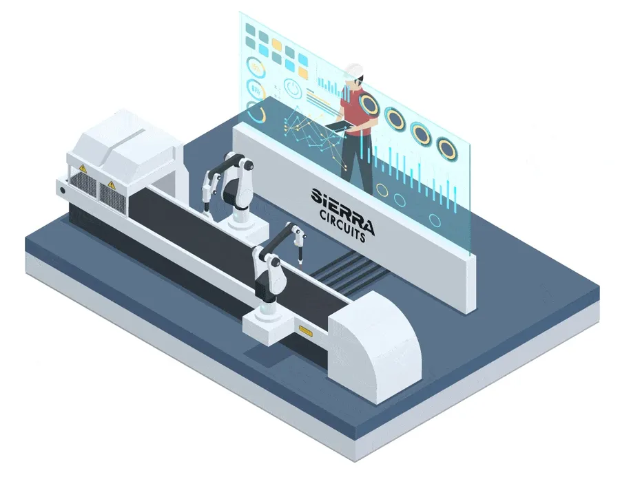
The manufacturing of a Printed Circuit Board (PCB) is a multi-stage process that transforms a design concept into a functional electronic component. It encompasses design, fabrication, assembly, and testing phases, each critical to the PCB's overall performance and reliability. This process demands precision and adherence to stringent quality control measures.
- Design Phase
This initial stage involves capturing the circuit schematic, designing the physical layout of the PCB, and generating Gerber files, which are the standard file format for PCB fabrication. It's essential to adhere to design rules and constraints to ensure manufacturability and optimal electrical performance. The design phase also encompasses component selection, considering factors like size, availability, and electrical characteristics. - Fabrication Phase
The fabrication phase begins with the chosen substrate material, typically FR-4. The process includes creating conductive pathways (copper traces) through etching, drilling holes for vias and component mounting, and plating processes to ensure conductivity and solderability. The order of these steps can vary depending on the complexity and layer count of the PCB. - Assembly Phase
This involves placing electronic components onto the PCB using automated pick-and-place machines or manual methods. Solder paste is applied to pads, and components are positioned before being secured through soldering techniques like reflow soldering. This stage is crucial for establishing reliable electrical connections. - Testing Phase
The final stage involves rigorous testing to ensure the PCB meets design specifications and operates correctly. This phase includes functional testing, continuity testing, and other quality checks to identify any defects or flaws before the final product is deployed. Test methods may include in-circuit testing (ICT) and flying probe testing.
PCB Design Considerations

Effective PCB design goes beyond simply connecting components; it requires careful consideration of various factors to ensure functionality, reliability, and performance. These considerations include signal integrity, thermal management, impedance control, and adherence to design rule checks (DRC).
- Signal Integrity
Maintaining the quality of electrical signals as they travel through the PCB is paramount. This includes minimizing signal reflections, crosstalk, and signal loss, which can distort signals and affect circuit performance. Factors include trace impedance, trace length, and component placement. - Thermal Management
The heat generated by components during operation can lead to performance degradation or even damage. Effective thermal management is critical, involving heat sinks, thermal vias, and proper component placement to dissipate heat efficiently and maintain stable operating temperatures. - Impedance Control
Controlling the impedance of signal traces is essential for high-speed signal transmission. Improper impedance matching can lead to signal reflections and degradation. Trace width, dielectric constant, and layer stack-up are key factors influencing impedance. - Design Rule Checks (DRC)
Adhering to design rules ensures the manufacturability and reliability of the PCB. DRCs specify minimum trace widths and spacing, pad sizes, and via clearances. Violating these rules can lead to manufacturing defects, so using a proper DRC tools are necessary.
PCB Materials and Their Properties
The performance and reliability of a Printed Circuit Board (PCB) are significantly influenced by the materials used in its construction. This section delves into the common materials like FR-4, polyimide, and metal cores, detailing their properties and ideal applications, while also addressing critical material selection considerations based on application demands.
| Material | Description | Key Properties | Typical Applications | Considerations |
|---|---|---|---|---|
| FR-4 | A composite material made from woven fiberglass cloth with an epoxy resin binder. It is the most common material used in PCB fabrication. | Good mechanical strength, good electrical insulation, moderate cost, flame retardant. | Most general-purpose PCBs, consumer electronics, and standard industrial applications. | Suitable for common applications, but limitations in high-frequency and high-temperature environments. |
| Polyimide | A high-performance polymer with excellent thermal and mechanical stability. | High temperature resistance, excellent flexibility, good chemical resistance. | Flexible circuits, high-temperature applications, aerospace, and automotive industries. | Higher cost than FR-4, but superior performance in demanding environments. |
| Metal Core (e.g., Aluminum, Copper) | Metal substrates used to improve thermal performance and heat dissipation. | Excellent heat dissipation, mechanical strength, dimensional stability. | LED lighting, power electronics, high-power applications. | Heavier and more expensive than FR-4, but necessary for applications with high thermal loads. |
| Rogers Materials | High frequency laminates which offer lower dielectric constant and lower loss. | Low dielectric loss, good high frequency performance. | RF circuits, antennas, high-speed data applications | More expensive but crucial for high performance applications. |
Material selection for PCB fabrication should take into account various requirements, including: Operating temperature, electrical performance requirements (such as impedance and dielectric loss), mechanical stress, cost considerations, and regulatory compliance. Understanding these factors is paramount to choosing the right material and ensuring the performance and longevity of the designed product.
Applications of PCB Boards
Printed circuit boards (PCBs) are fundamental components in a vast array of modern electronic devices, serving as the backbone for electrical connectivity and physical support. Their versatility has led to their integration across diverse industries, each leveraging the unique properties of PCBs to enable specific functionalities and technological advancements.
PCBs are indispensable in various sectors, with applications ranging from everyday consumer electronics to sophisticated industrial and aerospace systems. This section highlights key areas where PCB boards play a crucial role:
- Consumer Electronics
PCBs are integral to smartphones, laptops, tablets, and wearable devices, facilitating compact designs and efficient operation. They enable the complex interconnections required for these high-density electronics. These boards manage everything from power distribution to signal processing and data transfer. - Computers and Networking
In desktop computers, servers, and network infrastructure (routers, switches), PCBs provide a structured platform for complex circuitry, ensuring reliable signal transmission and processing. High-speed PCBs are essential for data centers, handling massive data throughput. - Telecommunications
PCBs are the foundation of communication systems, from mobile networks to satellite communication. They handle signal amplification, modulation, and filtering, enabling clear and consistent communication across vast distances. - Automotive Industry
Automotive PCBs are deployed in engine control units (ECUs), infotainment systems, and advanced driver-assistance systems (ADAS). They withstand harsh conditions and high vibrations, ensuring vehicle safety and reliability. Automotive PCBs also support autonomous driving technologies and electric vehicle controls. - Aerospace and Defense
Aerospace and defense applications demand high-reliability PCBs with robust performance under extreme temperatures and pressures. These PCBs support critical systems like avionics, guidance systems, and military communication networks. They adhere to stringent quality and performance standards. - Industrial Control Systems
In manufacturing plants and automation systems, PCBs control machinery, manage processes, and collect sensor data, ensuring efficient and safe operations. They facilitate data acquisition and automated control, improving productivity and precision. - Medical Equipment
PCBs are crucial in diagnostic and therapeutic medical devices, such as imaging machines, patient monitoring systems, and implants. High-precision and reliability are paramount in these applications to ensure patient safety and accurate data acquisition. - Emerging Trends
The future of PCB applications includes innovative uses in IoT devices, renewable energy systems, and AI hardware. PCB technology is evolving to support higher densities, greater flexibility, and improved environmental performance.
Frequently Asked Questions About PCB Boards
This section addresses common queries regarding printed circuit boards (PCBs), providing clear and concise answers to help users understand various aspects of these essential electronic components.
- How much does it typically cost to replace a PCB on a device, such as a boiler?
The cost to replace a PCB varies widely depending on the device, the complexity of the PCB, and the manufacturer. For a boiler, costs can range from a few hundred to over a thousand dollars, including labor. It's best to consult a certified technician for an accurate estimate. - Why are PCB boards often perceived as expensive?
The cost of PCBs is driven by several factors: the materials used (like FR-4 or specialized substrates), the complexity of the board (number of layers, trace density), the precision required in manufacturing, and the relatively low volume production runs for many applications. High-reliability applications such as aerospace and medical devices necessitate additional design, manufacturing, and testing, which adds significantly to the cost. - What is the primary function of a PCB in an electronic device?
A PCB serves as both the mechanical foundation and the electrical infrastructure for electronic components. It provides physical support for components and facilitates electrical connections via conductive traces, allowing the device to perform its intended function. Without PCBs, modern electronics would be impractical to assemble and highly unreliable. - How can I troubleshoot and fix a faulty PCB board?
Troubleshooting a faulty PCB board requires a systematic approach and specialized skills. Common issues include component failures, trace breaks, and solder joint problems. The process often involves visual inspection, use of multimeters, and sometimes more advanced equipment like oscilloscopes. Repair methods range from replacing faulty components to repairing damaged traces, but precise handling is necessary to avoid further damage. Due to the complexity of most repairs, seeking professional help is often the most reliable route. - What are the key factors affecting the price of a PCB board?
Several key factors influence the price of a PCB, including: material type (FR-4, polyimide, metal core, etc.), number of layers (single-sided, double-sided, multi-layer), board size and complexity, minimum trace width and spacing, via types and density, surface finish requirements, and production volume. Tighter tolerances and specialized materials lead to higher costs. - What are some common problems that cause a PCB to fail?
PCBs can fail due to several reasons such as electrical overstress, improper soldering, moisture exposure, thermal stress from heat dissipation, component aging, physical damage (cracks, bends), and manufacturing defects. These issues can lead to a range of problems, from intermittent malfunctions to complete device failure. - What is the meaning of 'PCB' in electronics?
In electronics, 'PCB' stands for Printed Circuit Board. It's a fundamental building block of almost every electronic device, providing a structured method to connect electronic components using conductive pathways etched onto a non-conductive substrate.
In conclusion, PCB boards are essential to modern electronics, serving as the backbone for nearly every electronic device. Understanding their design, manufacturing process, and diverse applications is crucial for anyone involved in electronics or related fields. The advancement of PCB technology is constantly evolving, driving innovation and progress across industries. As technology continues to advance, PCB boards will continue to play a crucial role in shaping our future.