Electric circuits, the lifeblood of modern technology, power everything from our smartphones to our homes. At the heart of these circuits lie various essential components, each playing a critical role in controlling the flow of electricity. Understanding these components, from the humble battery to the sophisticated integrated circuit, is key to grasping how our electrical world functions. This article will guide you through these fundamental elements and their functions, offering a practical and easy-to-understand overview.
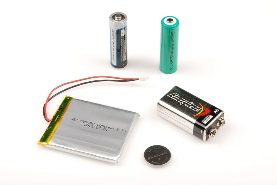
Power sources are fundamental to the operation of any electrical circuit, providing the necessary energy to drive the flow of electrons. These sources, primarily batteries and other voltage generators, convert chemical, mechanical, or solar energy into electrical energy, enabling the functionality of connected components.
Batteries, a ubiquitous form of power source, are categorized into primary and secondary cells. Primary cells are designed for single use and cannot be recharged, while secondary cells are rechargeable, allowing for repeated use. Each type exhibits unique characteristics in terms of voltage, current capacity, and internal resistance, which are crucial factors in circuit design.
| Characteristic | Primary Cells | Secondary Cells |
|---|---|---|
| Rechargeability | Not Rechargeable | Rechargeable |
| Typical Examples | Alkaline, Zinc-Carbon | Lithium-ion, Nickel-metal hydride |
| Initial Cost | Lower | Higher |
| Typical Applications | Remote controls, Toys | Mobile phones, Electric vehicles |
Beyond batteries, other power sources include solar cells, which convert light into electrical energy, and power supplies, which convert AC mains power to usable DC voltages, each designed for specific applications. The selection of the appropriate power source is determined by factors such as voltage requirements, current demands, energy capacity, and application environment, highlighting the essential nature of power sources in electrical systems.
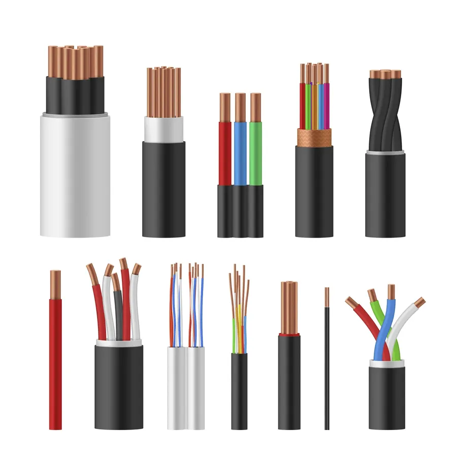
Conductors are the essential materials that facilitate the flow of electric current within a circuit. They provide a low-resistance pathway for electrons to move from a power source to various components, enabling the circuit to function effectively. The selection of appropriate conducting materials and their physical dimensions are crucial for the performance and safety of any electrical system.
| Property | Description | Importance in Conductors |
|---|---|---|
| Conductivity | The ability of a material to allow electric current to flow through it easily. | High conductivity is desired to minimize energy loss and heat generation. |
| Resistance | The opposition that a material offers to the flow of electric current. | Low resistance is essential for efficient current flow. Higher resistance leads to energy loss. |
| Wire Gauge (AWG) | Standardized measure of wire diameter. | Determines the current-carrying capacity of the wire, with smaller gauge numbers representing thicker wires. |
| Material | The substance from which the conductor is made, e.g., copper, aluminum. | Each material has different conductivity and cost characteristics. Copper is widely used due to its high conductivity. |
| Temperature Coefficient | How a material's resistance changes with temperature. | Important for designing circuits that operate at a wide range of temperatures. Copper is known for its relatively stable temperature coefficient. |
The most commonly used conductors are metals such as copper and aluminum, each offering a different combination of conductivity, cost, and physical properties. Copper is favored for its excellent conductivity and lower resistance, making it ideal for many electronic applications. Aluminum is often used in power transmission due to its lower density and cost, though it has lower conductivity than copper.
Wire gauge, measured by the American Wire Gauge (AWG) standard, is a critical parameter for determining the current-carrying capacity of a conductor. Thicker wires (smaller AWG numbers) have lower resistance and can carry higher currents without overheating, making them suitable for high-power applications. Conversely, thinner wires (larger AWG numbers) are used for lower current applications. Correct wire gauge selection is crucial to prevent overheating and electrical hazards.
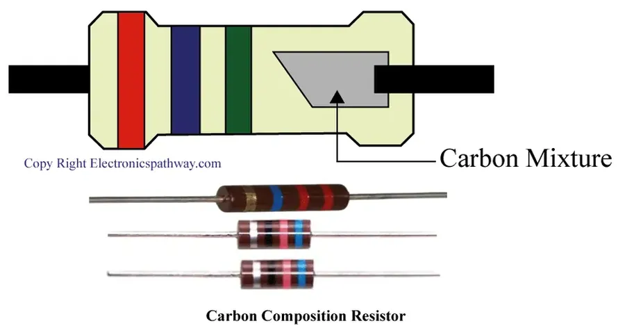
Resistors are fundamental passive components in electrical circuits, designed to impede the flow of electric current. They are characterized by their resistance value, measured in ohms (Ω), and play a critical role in controlling current levels, dividing voltage, and dissipating energy as heat. The strategic use of resistors is essential for proper circuit operation and protection.
| Resistor Type | Description | Typical Applications | Advantages | Disadvantages |
|---|---|---|---|---|
| Fixed Resistors | Resistors with a constant, predetermined resistance value. Color codes or numerical markings specify the resistance. | Current limiting, voltage division, and general-purpose applications. | Inexpensive, reliable, and widely available. | Limited to a single resistance value. |
| Variable Resistors (Potentiometers/Rheostats) | Resistors whose resistance value can be adjusted by manually turning a knob or sliding a contact. Used as potentiometers for voltage division and rheostats for current control. | Volume controls, dimmers, and adjustable settings in electronic devices. | Adjustable resistance value, flexibility in circuit design. | Can wear out over time, less precision than fixed resistors. |
| Special-Purpose Resistors | Include thermistors (temperature-sensitive resistors), photoresistors (light-sensitive resistors), and varistors (voltage-dependent resistors). Their resistance changes in response to environmental factors. | Temperature sensing, light detection, surge protection in circuits. | Specialized functionality for specific applications. | May have non-linear characteristics, more expensive than general-purpose resistors. |
Resistors are critical for several key circuit functions, primarily current limiting and voltage division. Current limiting protects sensitive components from excessive current flow, while voltage division is vital for adjusting voltage levels within a circuit for specific functional needs. The power rating of a resistor is also important, as it specifies the maximum power (in watts) that the resistor can safely dissipate as heat before it fails.
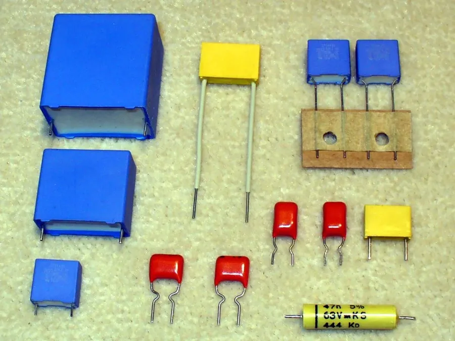
Capacitors are fundamental passive components in electrical circuits, renowned for their ability to store electrical energy in an electric field. This energy storage capability is transient, distinguishing capacitors from batteries. They are crucial in various applications, from filtering out unwanted noise to providing timing in circuits.
Capacitors are characterized by their capacitance (measured in Farads), voltage rating, and other performance parameters. They come in various types, each tailored for specific applications.
| Capacitor Type | Dielectric Material | Typical Capacitance Range | Key Applications | Advantages | Disadvantages |
|---|---|---|---|---|---|
| Ceramic | Ceramic | pF to µF | Bypass, decoupling, high frequency applications | Small size, low cost, wide range of values | Limited stability with temperature, limited voltage range |
| Electrolytic | Aluminum oxide (or tantalum pentoxide) | µF to mF | Power supply filtering, large energy storage | High capacitance in small size, good for low frequency | Polarized, higher leakage current, limited frequency response, may age |
| Film | Various plastics (polyester, polypropylene) | pF to µF | Precision circuits, audio applications | High stability, low losses, low self-inductance | Larger size compared to ceramic for same capacitance, higher cost |
| Supercapacitors (Ultracapacitors) | Activated carbon, porous carbon | F to kF | Energy storage, backup power | High energy density, fast charge/discharge | Lower voltage operation, more costly |
Capacitors are utilized in several key areas of circuit design:
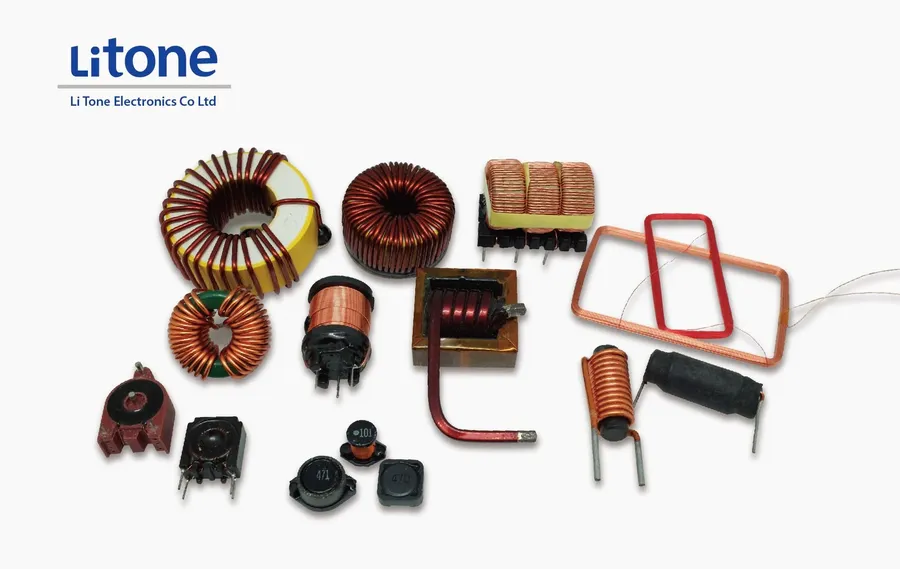
Inductors are fundamental passive components in electrical circuits that store energy in a magnetic field when an electric current passes through them. They are characterized by their inductance, measured in Henries (H), which quantifies their ability to resist changes in current. This property makes them crucial for filtering and tuning applications, as well as in energy storage and transformation.
| Parameter | Description | Typical Units |
|---|---|---|
| Inductance (L) | Measure of the inductor's ability to store magnetic energy. It is determined by the physical structure of the inductor, including coil turns, core material and coil dimensions. | Henries (H) |
| Current Rating | Maximum current an inductor can handle without damage or performance degradation. | Amperes (A) |
| DC Resistance (DCR) | Resistance of the inductor's wire to DC current; impacts efficiency and heat generation. | Ohms (Ω) |
| Saturation Current | Current level at which inductance begins to drop significantly due to core magnetic saturation. | Amperes (A) |
| Self-Resonant Frequency (SRF) | Frequency at which the inductor's parasitic capacitance causes it to act as a parallel resonant circuit. | Hertz (Hz) |
The behavior of an inductor can be described through mathematical relationships. The voltage across an inductor is proportional to the rate of change of current through it, expressed as V = L * (di/dt). Where V is voltage, L is inductance, and di/dt is rate of change of current with respect to time.
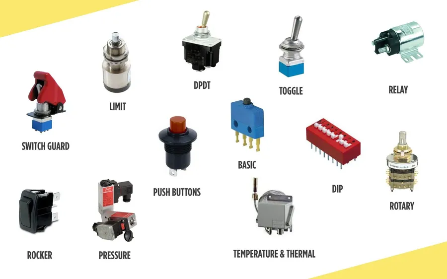
Switches are fundamental components in electrical circuits, serving as the control mechanisms for current flow. They function by selectively opening or closing a circuit, thereby enabling or interrupting the flow of electricity. These devices range from simple manual switches to more complex electronic types, each with specific applications and operational characteristics.
| Switch Type | Mechanism | Application | Key Characteristics |
|---|---|---|---|
| Manual Switches | Operated by human interaction (e.g., toggle, push-button, rotary) | Lighting, appliance controls, simple machine interfaces | Simple mechanical design, low cost, higher contact resistance |
| Electronic Switches | Activated by electrical signals (e.g., transistors, relays) | Digital circuits, automated systems, power control | High speed switching, lower contact resistance, may require control circuits |
| Relays | Electromechanical switches activated by a coil, allowing control of high current circuits with a low current signal | High-power circuit control, industrial equipment | Isolation between control and load circuits, slower switching speed |
| DIP Switches | Small switches grouped in a package, typically used for setting circuit configurations. | Board-level configuration settings | Small size, often used for permanent or semi-permanent circuit setups. |
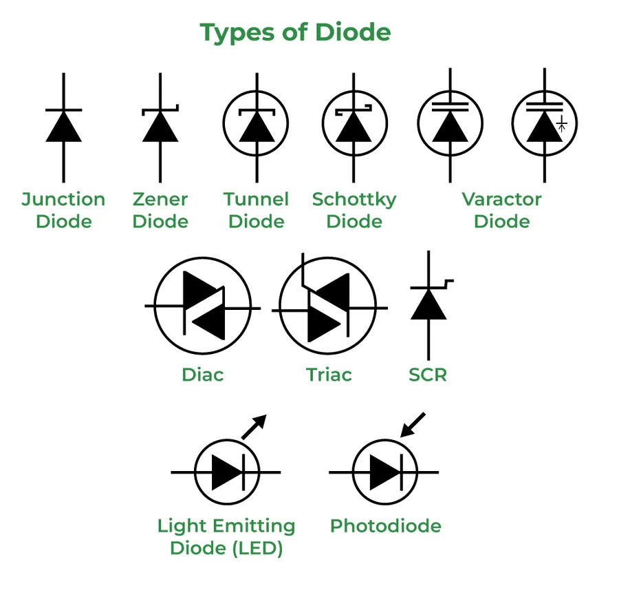
Diodes are fundamental semiconductor devices that exhibit a unique property: they allow electric current to flow predominantly in one direction, acting like a one-way valve for electrons. This unidirectional conduction is crucial for various electronic applications, notably in rectification, signal processing, and voltage regulation.
| Property | Description |
|---|---|
| Forward Voltage Drop (Vf) | The voltage drop across the diode when it's conducting current in the forward direction (typically 0.3V-0.7V for silicon diodes). |
| Reverse Breakdown Voltage (Vbr) | The reverse voltage that, if exceeded, causes the diode to conduct in the reverse direction, potentially damaging it. |
| Forward Current (If) | The maximum current the diode can handle safely in the forward direction |
| Reverse Leakage Current (Ir) | A small amount of current that flows in the reverse direction even when the diode is not broken down. |
| Junction Capacitance | The capacitance present at the p-n junction, which can affect circuit performance at high frequencies. |
Diodes are constructed using semiconductor materials, most commonly silicon, and their behavior is governed by the p-n junction formed within the device. The direction of current flow is determined by the polarity of the voltage applied across the diode. When a positive voltage is applied to the anode (p-side) and a negative voltage to the cathode (n-side), the diode becomes forward-biased and conducts current with a minimal voltage drop. Conversely, when the polarity is reversed, the diode is reverse-biased, blocking the current flow up to its reverse breakdown voltage.
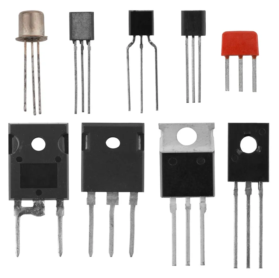
Transistors are fundamental semiconductor devices that act as the workhorses of modern electronics, enabling both signal amplification and switching functionalities within electric circuits. Their versatility stems from their ability to control electrical current flow, a property that makes them indispensable in various applications, ranging from simple switching circuits to complex integrated circuits.
There are two main categories of transistors: Bipolar Junction Transistors (BJTs) and Field-Effect Transistors (FETs), each with its own unique mode of operation. Understanding the differences between these two is critical in selecting the right component for a specific application.
| Feature | Bipolar Junction Transistor (BJT) | Field-Effect Transistor (FET) |
|---|---|---|
| Control Mechanism | Current-controlled current source | Voltage-controlled current source |
| Polarity | Bipolar (both majority and minority carriers) | Unipolar (majority carriers only) |
| Input Impedance | Low input impedance | High input impedance |
| Gain | Typically high current gain | Typically high voltage gain |
| Types | NPN, PNP | JFET, MOSFET (NMOS, PMOS) |
| Applications | Amplification, switching | Amplification, switching, logic circuits |
BJTs operate by using a small base current to control a larger collector current, utilizing both electrons and holes as charge carriers, which are referred to as bipolar. In contrast, FETs use an electric field to modulate current through a channel, thus controlling the drain current via the gate voltage. FETs are unipolar devices, relying on either electrons (in n-channel devices) or holes (in p-channel devices) as the charge carriers.
The operating characteristics of a transistor are described by parameters such as current gain (β or hFE for BJTs) or transconductance (gm for FETs), which quantify their amplification capabilities. Additionally, parameters such as saturation voltage, input impedance, and output impedance are used to model their behavior in circuits.
In circuit design, transistors are used in various configurations including common emitter, common collector, and common base for BJTs and common source, common drain, and common gate for FETs, each with different amplification and impedance characteristics. Transistors are the fundamental building blocks of operational amplifiers, logic gates, and many other electronic circuits, and an in-depth understanding of transistors is essential to any engineer engaged in circuit analysis.
This section addresses common queries regarding electric circuit components, providing practical insights into their selection and application. These questions delve into the core concepts of electrical circuits and their components.
Understanding the diverse array of electric circuit components, from basic resistors and capacitors to complex transistors and diodes, is crucial for anyone delving into electronics. These components, whether acting as power sources, conductors, or control elements, collectively enable the functionality of all electronic devices we use daily. As technology evolves, these fundamental components will continue to shape our world, playing vital roles in future innovations, reinforcing their significance in both current and emerging technologies.

