Fine-Tuning with Trimmer Resistors: A Comprehensive Guide

2025.02.04

Ever wondered how precise adjustments are made in electronic devices? Often the unsung hero is the trimmer resistor, also known as a trimpot. Like a fine-tuning dial on an old radio, these components allow minute alterations in resistance to ensure optimal circuit performance. This article will explore the world of trimmer resistors, explaining how they function, their various applications, and why they are crucial in many electronic systems.

What is a Trimmer Resistor?

A close-up of a small trimmer resistor.
Trimmer Resistor

A trimmer resistor, often called a trimpot, is a miniature adjustable potentiometer designed for infrequent, precise circuit adjustments. Unlike standard potentiometers intended for regular user interaction, trimmer resistors are typically set during manufacturing or calibration processes and are not meant for frequent adjustments.

Trimmer Resistor Construction and Working Principle

An illustration showing the internal construction of a trimmer resistor.
Trimmer Construction

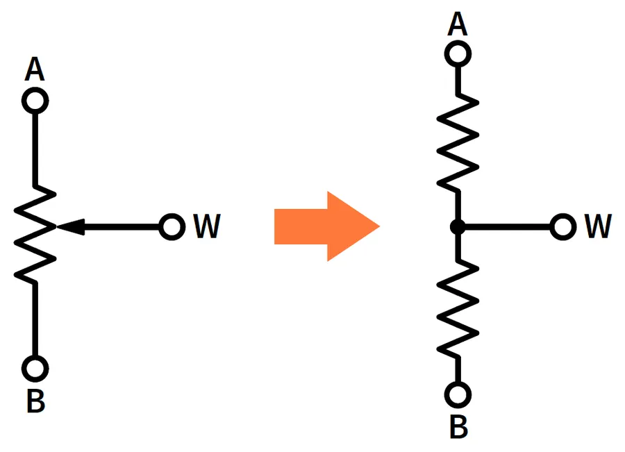
Trimmer resistors, also known as trimpots, function as adjustable voltage dividers achieved through a carefully engineered assembly of core components. These components, principally a resistive element, a wiper arm, and an adjustment mechanism, work in concert to provide variable resistance. The adjustment mechanism, often a screw or knob, enables precise control over the wiper's position along the resistive element.

The core working principle is centered on the movement of the wiper arm which is in direct contact with the resistive track. This movement is controlled through the adjustment mechanism (screw or knob). As the wiper arm traverses the resistive track, the effective length of the resistive material within the circuit changes, which directly corresponds to a change in the resistance between the terminals. This resistance is the key component in the circuit.

ComponentDescriptionFunction
Resistive ElementThe material that provides resistance; can be carbon, cermet, or wirewound.Determines the overall resistance range of the trimmer.
Wiper ArmA conductive arm that makes contact with the resistive element.Moves along the resistive element to adjust resistance.
Adjustment MechanismA screw or knob mechanism that controls the movement of the wiper arm.Allows for manual adjustment of the resistance.

The selection of resistive material impacts the trimmers specifications and performance characteristics. The primary materials used include carbon, cermet and wirewound.
  • Carbon Film
    Carbon film trimmers are cost-effective and suitable for general-purpose applications where precision isn't the primary concern. However, they exhibit higher temperature coefficients and may be less stable over time.
  • Cermet
    Cermet trimmers are known for their stability and precision and are better suited for high-accuracy applications, offering improved temperature stability and lower noise compared to carbon film trimmers.
  • Wirewound
    Wirewound trimmers offer high power handling and very low temperature coefficients, which makes them ideal for applications where temperature stability is critical. However, they are generally larger and more expensive than carbon or cermet trimmers.

Types of Trimmer Resistors

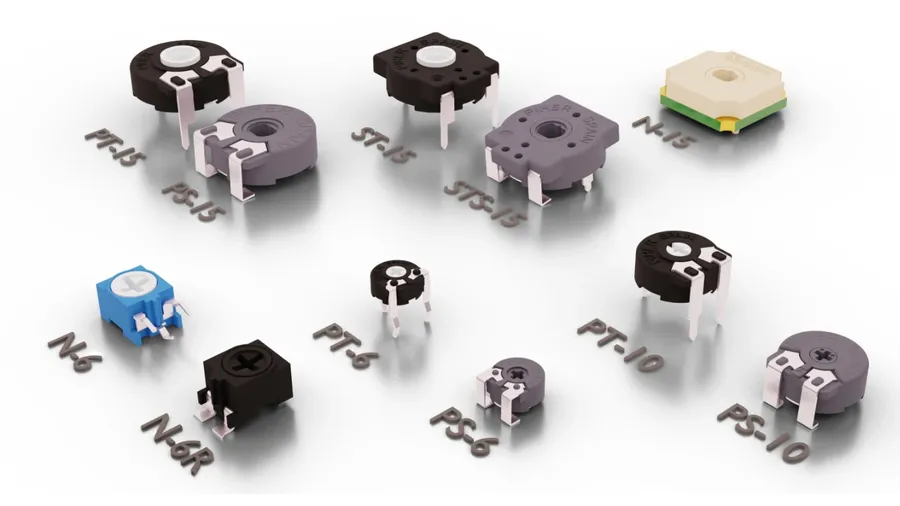
A collection of various types of trimmer resistors.
Trimmer Resistor Types

Trimmer resistors are available in several configurations, primarily distinguished by their adjustment mechanism and mounting style. These variations cater to different precision requirements and assembly processes, impacting their suitability for various applications. Understanding these differences is crucial for selecting the appropriate trimmer for a given design.

FeatureSingle-Turn TrimmerMulti-Turn Trimmer
Adjustment RangeFull resistance range achievable within one rotation.Full resistance range achievable over several rotations.
Precision of AdjustmentLower precision; adjustments can be less fine.Higher precision; allows for very fine adjustments.
Adjustment MechanismDirect rotation of the adjustment screw.Wiper moves with a screw mechanism over multiple turns, leading to finer control.
Typical ApplicationsApplications where coarse adjustments are sufficient.Applications needing highly precise calibration, such as sensitive sensors and analog circuits.

In addition to the adjustment mechanism, trimmer resistors are also categorized by their mounting method:

Mounting TypeDescriptionTypical Applications
Surface Mount Device (SMD)Designed for direct mounting onto the surface of a printed circuit board (PCB). Small in size and ideal for automated assembly processes.High-volume manufacturing; compact electronic devices where space is a constraint.
Through-HoleFeatures leads that are inserted through holes in the PCB. Suitable for manual assembly or prototyping.Prototyping, low-volume manufacturing, and applications where greater mechanical stability is needed.

Common package sizes for trimmer resistors include 3mm, 4mm, 6mm, and 10mm square or rectangular bodies. Understanding the specific dimensions is critical for board layout and component selection. Package sizes also influence the physical footprint on the PCB and can impact the ease of adjustment.
Trimmer Resistor vs. Potentiometer: Key Differences

A side-by-side comparison of a trimmer resistor and a potentiometer.
Trimmer Resistor and Potentiometer

While both trimmer resistors and potentiometers function as variable resistors, their intended use, construction, and application differ significantly. Potentiometers are designed for frequent, user-initiated adjustments, whereas trimmer resistors are intended for infrequent, precise calibration.

FeatureTrimmer ResistorPotentiometer
Primary ApplicationPrecise, infrequent circuit calibration and fine-tuning during manufacturing or serviceFrequent, user-controlled adjustments in circuits
Adjustment MechanismSmall screw or knob, often requiring a screwdriver; designed for less frequent adjustmentsKnob or slider easily manipulated by the user
Physical SizeGenerally smaller, often designed for PCB mountingTypically larger, designed for panel mounting and user accessibility
Durability of AdjustmentDesigned for minimal adjustments over product lifespan, focusing on stability after settingDesigned for repeated adjustments throughout product usage
Typical Application ExamplesCircuit calibration, sensor adjustments, bias adjustments in analog circuitsVolume controls, brightness adjustments, tone controls
MountingPrimarily Surface Mount Device (SMD) or through-hole on a PCBTypically panel mounted with a shaft extending for user adjustment
Adjustment PrecisionCan have multi-turn options for very precise adjustmentsGenerally single turn with less precise adjustment capabilities

The differentiation in design reflects the differing needs: trimmers prioritize stability and precision for set-and-forget adjustments, while potentiometers emphasize ease of use and frequent adjustment by the end-user. This distinction is crucial in selecting the correct component for the specific application requirements.
Applications of Trimmer Resistors

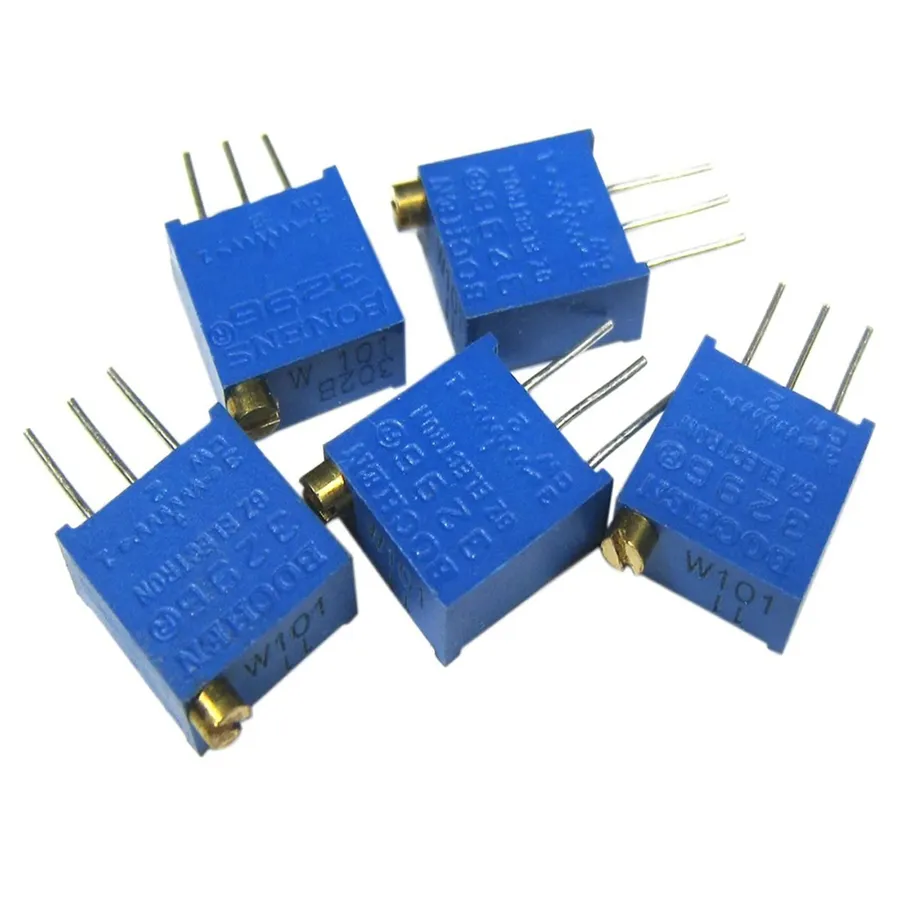
A trimmer resistor mounted on a circuit board.
Trimmer on PCB

Trimmer resistors are indispensable components for precise circuit adjustments, playing a crucial role in calibration, signal fine-tuning, and feedback control. Their ability to provide minute resistance alterations makes them essential in diverse electronic systems. Unlike potentiometers, which are designed for frequent user interaction, trimmer resistors are primarily intended for initial or infrequent adjustments during manufacturing or maintenance.

The primary function of trimmer resistors lies in the precise calibration of circuits. This is critical in applications where exact resistance values are necessary to meet specific performance criteria. By carefully adjusting the resistance, engineers can optimize circuit parameters, ensuring that components operate within the desired ranges. This adjustment might involve correcting for variations in component tolerances or compensating for environmental factors.

  • Audio Equipment
    In audio systems, trimmer resistors are used to fine-tune bias currents in amplifiers, adjust gain levels, and calibrate tone control circuits, ensuring optimal audio fidelity and performance. They ensure precise channel balance and minimal distortion.
  • Power Supplies
    Trimmer resistors are crucial in calibrating the output voltage and current of power supplies. They allow for precise adjustment to meet specific load requirements, ensuring that power is delivered reliably and consistently to other circuit elements. This is essential for maintaining stability and preventing damage to downstream components.
  • Industrial Control Systems
    In industrial automation, trimmers are used in calibrating sensors, adjusting signal ranges for control circuits, and setting precise feedback values in control loops. They are essential for maintaining the accuracy and reliability of industrial processes, ensuring accurate measurements and proper responses from equipment.
  • Sensor Calibration
    Trimmer resistors play a vital role in calibrating sensors to improve their accuracy and linearity. By fine-tuning the sensor response, trimmer resistors help to correct for manufacturing tolerances or temperature variations, ensuring that the sensor output provides the most accurate representation of the physical quantity it measures. This is critical in applications such as temperature, pressure, and light sensing where precision is key.
  • Amplifiers
    In amplifier circuits, trimmer resistors are employed to precisely adjust the feedback loop, set the amplifier's gain, and manage bias points. This control is vital for achieving the desired amplification characteristics and maintaining signal integrity. It also helps to optimize the amplifier's efficiency and reduce distortions.

Selecting the Right Trimmer Resistor: Key Considerations

Selecting the appropriate trimmer resistor is crucial for optimal circuit performance and reliability. This process requires a careful evaluation of several key parameters, each contributing to the component's suitability for a specific application. These parameters include resistance range, tolerance, temperature coefficient, power rating, and physical size/form factor. Proper selection, guided by datasheet specifications and a solid understanding of application needs, will ensure stable and accurate circuit adjustments.

ParameterDescriptionImportanceConsiderations
Resistance RangeThe minimum and maximum resistance values the trimmer can provide.Essential for covering the required adjustment range in the circuit.Ensure the range aligns with circuit design requirements; consider both ends of the range
ToleranceThe allowable deviation from the specified nominal resistance value.Impacts the precision of circuit calibration and signal level adjustments.Tighter tolerances result in higher accuracy, but may increase cost
Temperature CoefficientHow much the resistance changes with temperature variations.Critical in environments with fluctuating temperatures to maintain stable performance.Choose a component with a temperature coefficient that aligns with the operating temperature of the circuit; lower is better
Power RatingThe maximum power the trimmer can dissipate without damage.Prevents overheating and ensures the longevity of the component.The power rating must exceed the expected power dissipation in the circuit; calculate based on current and voltage
Physical Size/Form FactorThe physical dimensions and mounting style of the trimmer.Impacts the ease of integration and compatibility with the PCB or enclosure.Ensure that the physical size matches available space on the PCB and can be mounted securely; consider SMD vs through-hole

How to Adjust a Trimmer Resistor

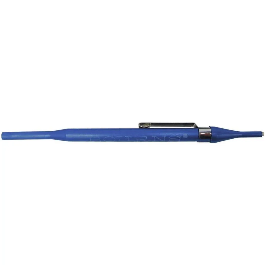
A special tool used to adjust a trimmer resistor.
Trimmer Adjustment Tool

Adjusting a trimmer resistor requires precision and care to ensure accurate circuit calibration. Unlike potentiometers designed for frequent manipulation, trimmers are intended for infrequent adjustments, often during initial setup or maintenance.

The following steps and considerations provide a detailed approach for accurately adjusting trimmer resistors:

  1. Preparation
    Before making any adjustments, ensure the circuit is powered off to prevent accidental damage or erroneous readings. Identify the trimmer resistor within the circuit and note its initial position or value if possible for reference.
  2. Tool Selection
    Use an appropriate non-metallic adjustment tool such as a small insulated screwdriver or a specialized trimmer adjustment tool. Metallic tools can cause unwanted shorts or damage to the component or surrounding circuitry. Ensure the tool tip fits the trimmer's adjustment mechanism (slot, screw, etc.) securely to prevent slipping.
  3. Initial Adjustment
    Insert the adjustment tool into the trimmer's adjustment mechanism. Make small, incremental turns rather than large, abrupt adjustments. Monitor the resistance or the circuit's behavior (e.g., voltage, signal level) as you make each change. Refer to the circuit schematic or documentation to ensure you're adjusting in the correct direction to achieve the desired outcome.
  4. Resistance Measurement
    Use a multimeter to measure the resistance across the trimmer's terminals while making adjustments if direct electrical measurements are required to calibrate the circuit. These readings provide a clear indication of the current resistance. If making changes during operation, monitor the relevant signal parameters instead of resistance.
  5. Single-Turn vs. Multi-Turn Considerations
    Single-turn trimmers cover the full range of resistance within a single rotation, making adjustments more immediate but less precise. Multi-turn trimmers require multiple rotations to cover the full range, providing much finer control and higher precision. Adjust multi-turn trimmers slowly to avoid overshooting the desired setting.
  6. Avoiding Over-Tightening
    Do not apply excessive force or over-tighten the adjustment mechanism as this can cause damage to the trimmer, stripping threads or the wiper arm mechanism. When you meet resistance, it's an indication you have reached the maximum or minimum value for the device or have reached the physical limit of the travel of the wiper arm.
  7. Finalization
    Once the desired setting has been reached and checked, power the circuit back on if it was off. Verify the final operating parameters. If further adjustment is needed repeat the steps. If the trimmer was set during calibration, consider sealing the adjustment mechanism to prevent accidental change in the future.

Frequently Asked Questions About Trimmer Resistors

This section addresses common questions regarding trimmer resistors, clarifying their use, function, and differences from other resistive components. We aim to provide concise, technically accurate answers to frequently asked questions, drawing from fundamental principles of electronics.

  • What is the primary function of a trimmer resistor?
    A trimmer resistor, also known as a trimpot, is primarily used for fine-tuning or calibrating circuits. Unlike standard potentiometers meant for frequent adjustments, trimmers are designed for infrequent changes, typically during manufacturing or maintenance, to achieve precise performance parameters in a circuit. This can include adjusting voltage levels, signal gains, or feedback settings within a device.
  • What does it mean to 'trim' a circuit?
    To 'trim' a circuit means to make small, precise adjustments to its components, typically using a trimmer resistor, to achieve optimal performance. This process involves varying the resistance of the trimmer until the desired electrical behavior of the circuit is achieved. Trimming is often critical for compensating for component tolerances or temperature variations, ensuring the circuit operates within its specified parameters. This process ensures that the system performs optimally.
  • What are the key differences between a trimmer resistor and a potentiometer?
    While both trimmer resistors and potentiometers are variable resistors, their intended usage differs significantly. Potentiometers are designed for frequent, manual adjustments, as seen in volume controls, and usually have a knob or dial for easy access. Trimmer resistors, on the other hand, are designed for infrequent adjustments, typically with a screw-type interface that requires a small tool for adjustment. They are smaller, more robust and primarily used for calibration and fine-tuning during manufacturing or maintenance.
  • How does a trimmer resistor differ from a fixed resistor?
    A fixed resistor has a single, unchanging resistance value determined during manufacturing, while a trimmer resistor's resistance can be adjusted within a certain range. Fixed resistors are used for setting static current and voltage levels, while trimmers are used where adjustability is needed for fine-tuning or calibration. Thus, trimmers provide dynamic variability, whereas fixed resistors are static by design. This crucial difference determines the function of each in a circuit.
  • Is a tapped resistor fixed, and how does it relate to a trimmer resistor?
    A tapped resistor has multiple fixed points (taps) along its resistive element, offering a selection of discrete resistance values, but these values are still pre-determined and not continuously variable. Unlike a trimmer, a tapped resistor's resistance can only be switched between pre-defined values. Trimmer resistors provide an adjustable range of resistance, offering more flexibility for circuit adjustments than a tapped resistor's limited discrete settings. Thus, trimmers and tapped resistors address different applications and design needs.
  • How are trimmer resistor values determined and specified?
    Trimmer resistor values are determined by their designed resistance range and the associated tolerance level, specified in ohms. The specific value refers to the maximum resistance of the trimmer, and within this, it can be adjusted to any point. Datasheets list the nominal resistance, the tolerance which specifies a variance, as well as the operating temperature and power dissipation capabilities. These values are crucial for circuit design and selection to ensure that the trimmer functions safely and within design parameters. Understanding the datasheet is paramount to effective component selection.

Troubleshooting Common Issues with Trimmer Resistors

Trimmer resistors, while robust for their intended purpose of infrequent adjustment, can exhibit problems over time or due to environmental factors. Understanding common issues and their solutions ensures the longevity and reliability of circuits relying on these components. This section outlines practical steps for identifying and resolving common trimmer resistor problems, including when replacement is necessary.

  • Noisy Operation or Erratic Readings
    Noisy operation, characterized by unstable or fluctuating readings, is often caused by poor contact between the wiper arm and the resistive element. This can result from oxidation, corrosion, or physical wear. A potential solution is to gently rotate the trimmer through its entire range several times to clean the contact surfaces. In some cases, applying a contact cleaner may help, provided it's compatible with the trimmer's materials.
  • Intermittent Connections
    Intermittent connections, where the circuit unexpectedly opens or becomes unstable, may be caused by a loose terminal connection or internal damage to the trimmer. Visually inspect the solder joints and terminals for any signs of damage. If the trimmer itself is suspected, gentle pressure on the body or terminals might reveal a loose connection. The trimmer may need to be resoldered or replaced.
  • Inability to Adjust or Stiff Adjustment
    If the trimmer is difficult or impossible to adjust, it may be due to excessive contamination, physical damage or the adjustment mechanism is stripped. Forcing a stiff trimmer can break the internal contacts or mechanism. If cleaning does not help, replacement is often the best solution. Careful consideration should be given to replacing it with a component of the exact same type and value.
  • Drift in Resistance Value
    A drift in resistance value over time can indicate issues with temperature coefficient or internal degradation of the resistive element. If the application requires high precision, it is recommended to use a higher quality trimmer that meets the precision requirement and environmental stability. If the drift is significant and not acceptable for the application, replacement may be necessary.
  • Damaged Trimmer
    Physical damage, such as a cracked body, bent terminals, or stripped adjustment mechanism is a clear indication that the trimmer needs replacement. Over-tightening or using improper tools are a common cause. When replacing a damaged trimmer, a new trimmer of the same value, type, and physical dimensions is required to assure a proper fit and function.

When replacement is necessary, always choose a trimmer resistor that matches the original specifications, including resistance value, type (e.g., carbon, cermet, wirewound), physical size, and mounting style. Ensure proper desoldering and soldering techniques to prevent damage to the new trimmer or the circuit board. Always disconnect power before attempting any component replacement or adjustment.

In conclusion, trimmer resistors are vital components for precise circuit adjustments and calibration. From their role in audio equipment to power supplies, they enable fine-tuning for optimal system performance. Understanding their construction, various types, and how to select the right one is key to successful circuit design. Like a meticulous craftsman refining a design, a trimmer resistor allows for small tweaks that make a significant difference, showcasing the importance of detail in electronics. The evolution of trimmer resistor design continues to enhance our technological capabilities, and they will remain essential for years to come.


Anypcba