
In the world of high-performance electric mobility, the motor controller is the beating heart of the system. As e-bike power output increases, so does the demand for effective heat dissipation. Choosing the wrong metal-core PCB (MCPCB) substrate isn't just a design oversight—it's a recipe for component failure. This guide breaks down the technical parameters you must evaluate to ensure your propulsion system stays cool under peak load.
Understanding the Role of Metal-Core PCBs in E-Bikes
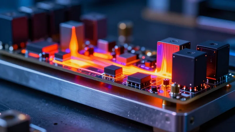
The Limitations of FR4 in High-Power Motor Drives
Standard FR4 substrates, composed of glass-reinforced epoxy laminate, act as thermal insulators. In e-bike motor controllers, where high current densities generate significant ohmic heat, FR4 lacks the thermal conductivity required to prevent premature component failure. This thermal bottleneck causes MOSFETs and gate drivers to exceed their safe operating temperatures, leading to thermal runaway and degraded system reliability.
Advantages of Aluminum Substrates
Aluminum-based PCBs leverage a metal base layer to act as an integrated heat sink. This architecture facilitates rapid heat transfer from the junction of the power semiconductors to the chassis or external heat sink, maintaining component longevity under extreme load conditions common in high-performance electric drive systems.
| Feature | FR4 Substrate | Aluminum Substrate |
|---|---|---|
| Thermal Conductivity | Low (0.25 W/mK) | High (1.0 - 3.0 W/mK) |
| Heat Dissipation | Poor (Insulative) | Excellent (Conductive) |
| Mechanical Durability | Standard | Superior |
| Cost | Low | Moderate |
Common Considerations for E-Bike Engineers
- Why is thermal resistance critical for e-bike controllers?
Lower thermal resistance allows the motor controller to handle higher continuous current without throttling performance, ensuring consistent acceleration and torque. - Does an aluminum PCB replace the need for an external heat sink?
No, it enhances the efficiency of the heat path, allowing for more compact heat sink designs or better performance within the same physical footprint. - How does the dielectric layer impact performance?
The thin dielectric layer between the copper foil and aluminum base is the limiting factor for heat transfer; choosing a high-conductivity dielectric is essential for high-performance applications.
Evaluating Thermal Conductivity (W/m·K) Ratings
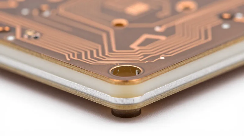
The Role of the Dielectric Layer in Thermal Pathing
The thermal conductivity of an aluminum PCB is almost entirely defined by the thin dielectric layer situated between the copper circuit and the aluminum base. While standard FR4 materials offer poor thermal performance (typically 0.25 W/m·K), specialized thermal dielectrics engineered for metal-core PCBs range from 1.0 W/m·K to 8.0 W/m·K or higher. For high-performance e-bike controllers, the goal is to reduce thermal resistance—the measure of how effectively heat moves from the MOSFET junction to the aluminum heat sink—thereby maintaining lower operating temperatures during high-current bursts.
Thermal Performance Comparison Table
| Dielectric Type | Thermal Conductivity (W/m·K) | Application Suitability |
|---|---|---|
| Standard FR4 | 0.25 | Not recommended for high-power controllers |
| Entry-level Thermal | 1.0 - 2.0 | Standard commuters, low-power hub motors |
| High-Performance Ceramic | 3.0 - 5.0 | Performance e-bikes, mid-drive systems |
| Extreme Thermal | 6.0+ | Competition, racing, high-load industrial |
FAQs on Thermal Conductivity Selection
- Does a higher W/m·K rating always guarantee better performance?
Not necessarily. While higher conductivity improves heat dissipation, the physical thickness of the dielectric layer also impacts total thermal resistance. Engineers must balance conductivity with the necessary dielectric breakdown voltage rating to ensure safety. - Why should I avoid the cheapest dielectric material?
Cheaper materials often suffer from poor thermal aging, leading to micro-cracks under the repeated thermal cycling inherent in e-bike acceleration and braking. This can cause long-term reliability failures in motor controller MOSFETs. - How do I calculate the required rating for my controller?
You must calculate the total heat dissipation requirements of your MOSFET array during peak amperage. If the thermal resistance of your board is too high, the junction temperature of your semiconductors will exceed their maximum threshold, leading to failure or immediate power limiting.
The Critical Importance of Dielectric Breakdown Voltage
The Critical Importance of Dielectric Breakdown Voltage
In high-performance e-bike motor controllers, the dielectric layer serves as the thin insulating bridge between high-current power components like MOSFETs and the thermally conductive aluminum base plate. The dielectric breakdown voltage defines the threshold at which this insulation fails, allowing current to arc directly into the metal core. In e-bike applications, where systems often fluctuate between high voltages and intense thermal expansion, an insufficient dielectric rating is a primary cause of catastrophic controller failure.
Comparing Dielectric Performance Ratings
| Dielectric Type | Breakdown Strength (kV/mm) | Application Suitability |
|---|---|---|
| Standard Epoxy | 2.0 - 3.0 | Low-power commuter systems |
| High-Performance Ceramic-Filled | 4.0 - 6.0 | Performance e-bike motor controllers |
| Specialized Polyimide | 7.0+ | Extreme thermal/high-voltage industrial |
Key Considerations for Dielectric Selection
- How does operating voltage influence selection?
The dielectric breakdown voltage must maintain a safety margin of at least 3x the peak operating voltage of your motor controller to account for transient spikes and ripple currents. - Does thermal stress weaken the dielectric?
Yes. Constant thermal cycling from power MOSFETs can induce micro-cracks in the dielectric. Higher breakdown voltage materials often feature better structural integrity under continuous thermal fatigue. - What happens if the breakdown voltage is too low?
Electrical shorts occur when the insulation breaks down, which usually results in the immediate destruction of the MOSFET bridge and potential physical damage to the aluminum base due to arcing.
Copper Foil Thickness: Balancing Current and Heat
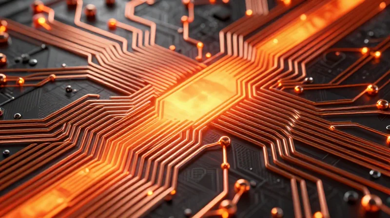
The Physics of Current and Thermal Resistance
In high-performance e-bike controllers, the copper foil serves as both the primary electrical path and a vital thermal spreader. Thicker copper significantly reduces electrical resistance, which directly lowers resistive (I²R) power losses—the primary driver of internal heating within the PCB. By choosing the correct foil thickness, engineers can minimize voltage drop during high-amperage surges, ensuring that motor torque is maintained even under heavy mechanical loads.
Comparing Copper Weight and Performance
| Copper Weight (oz) | Nominal Thickness (µm) | Primary Application | Thermal Benefit |
|---|---|---|---|
| 1 oz | 35 µm | Logic and Sensing | Standard heat spreading |
| 2 oz | 70 µm | Mid-Power Controllers | Improved heat distribution |
| 3+ oz | 105+ µm | High-Current Drive Stage | Maximum heat dissipation |
Trade-offs and Design Considerations
While increasing copper thickness provides clear electrical advantages, it introduces manufacturing challenges that can impact product reliability if not carefully managed.
- Does thicker copper impact etching precision?
Yes, standard etching processes have limits. Extremely thick copper requires wider trace spacing and larger pads to account for undercut during the chemical etching process. - How does copper thickness affect thermal mechanical stress?
Thicker copper has a different coefficient of thermal expansion compared to the dielectric layer, which can increase the risk of delamination or solder joint fatigue during high-temperature cycling. - Should I choose 3oz copper for all layers?
No. Apply heavier copper only to the high-current power stages. Using excessive copper on signal layers increases costs and complicates the fabrication of fine-pitch components.
Ultimately, the selection process should prioritize the current-carrying requirements of the motor phase traces. Using industry-standard calculators (like IPC-2221) while considering the heat-sinking effect of the aluminum base is essential for a robust, high-performance controller design.
Assessing Thermal Expansion and Mechanical Reliability
The Mechanics of CTE Mismatch in High-Performance Controllers
In high-performance e-bike controllers, the power MOSFETs and the aluminum base operate under extreme thermal fluctuations. The Coefficient of Thermal Expansion (CTE) defines how much a material expands when heated; when the CTE of the ceramic or dielectric layer significantly deviates from that of the aluminum base or the copper circuitry, mechanical stress concentrates at the interfaces. Over thousands of start-stop cycles, this mismatch manifests as micro-cracking in the solder joints and delamination of the dielectric, eventually leading to catastrophic electrical failure.
Comparative Impact of Thermal Cycling
| Material Property | Aluminum Base | Typical Dielectric | Copper Circuit |
|---|---|---|---|
| CTE (ppm/°C) | ~23.0 | ~5.0 to 10.0 | ~17.0 |
| Thermal Stress Potential | High | Critical (Interface) | Moderate |
Strategies for Mechanical Reliability
To mitigate these risks, engineers must prioritize substrates featuring thermally matched, reinforced polymer dielectrics. These materials are engineered to have a CTE that transitions more gracefully between the rigid aluminum and the flexible copper layers, effectively distributing localized stress rather than allowing it to accumulate at a single point.
- How does high thermal conductivity affect CTE requirements?
High-conductivity fillers in dielectrics, such as ceramic particles, often lower the dielectric's CTE. While beneficial for heat transfer, excessive filler can make the dielectric brittle, increasing the risk of cracking under vibration. - What is the role of the aluminum base thickness?
A thicker aluminum base provides structural rigidity that helps minimize PCB warping, but it also increases the thermal mass, which can lead to longer periods of expansion stress during rapid acceleration phases. - Are there specific industry standards to check?
Engineers should look for IPC-compliant metal-clad laminates that undergo rigorous thermal shock testing, typically simulating cycles from -40°C to +125°C to ensure bond integrity.
Comparing Aluminum vs. Copper Core Substrates
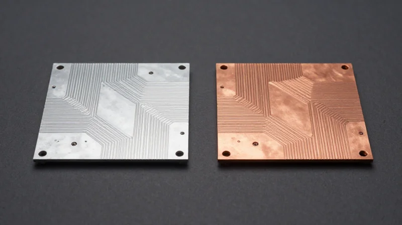
Core Material Comparison: Aluminum vs. Copper
While aluminum-based substrates (IMS - Insulated Metal Substrates) are the industry standard for most e-bike motor controllers due to their cost-efficiency and lightweight nature, copper core substrates offer superior thermal conductivity for ultra-high performance applications. The choice hinges on the heat dissipation demands of your power MOSFET stage and the peak current density of the controller.
| Metric | Aluminum Core | Copper Core |
|---|---|---|
| Thermal Conductivity | ~2.0 - 3.0 W/mK | ~380 - 400 W/mK |
| Weight | Lightweight | Heavy |
| Cost | Economical | High |
| CTE Compatibility | Moderate | High (Better match for Copper traces) |
When to Upgrade to Copper
You should consider an upgrade to copper core substrates when your design encounters 'thermal bottlenecks' that aluminum cannot resolve. If your e-bike controller operates in restricted airflow environments or requires continuous high-current delivery (above 100A), copper’s ability to move heat away from high-density hotspots minimizes the risk of junction temperature degradation.
- Is copper core always better for thermal performance?
Yes, copper has significantly higher thermal conductivity than aluminum, but it adds substantial weight and cost, which may negate benefits in budget-conscious or lightweight e-bike builds. - How does CTE affect this choice?
Copper core substrates match the Coefficient of Thermal Expansion of copper traces more closely than aluminum. This reduces mechanical stress on solder joints during rapid thermal cycling, significantly increasing the reliability of controllers in extreme climates. - Can I use thicker aluminum to match copper performance?
Increasing aluminum thickness helps, but it cannot overcome the fundamental conductivity difference; eventually, the thermal resistance of the dielectric layer becomes the limiting factor regardless of core material.
Manufacturing Standards and Quality Assurance Protocols
Mandatory Manufacturing Standards for Aluminum PCBs
For e-bike motor controllers, adherence to IPC-6012 (Qualification and Performance Specification for Rigid Printed Boards) is non-negotiable. Suppliers must guarantee that the dielectric layer—the thermal interface between the copper circuit and the aluminum base—is free from voids or contamination. Inconsistent dielectric thickness can lead to premature electrical breakdown under the high-frequency switching common in MOSFET-based motor drive stages.
Quality Assurance Protocols and Reliability Testing
To validate long-term reliability in the field, manufacturers must implement a multi-stage testing regimen that addresses the unique mechanical stresses of automotive-grade power electronics.
| Test Protocol | Purpose for E-Bike Controllers | Target Metric |
|---|---|---|
| Thermal Shock Testing | Simulates aggressive thermal cycling during motor acceleration and braking. | -40°C to +125°C, 500+ cycles |
| High-Pot Dielectric Testing | Verifies integrity of the thermal pre-preg layer to prevent short-circuits. | 3kV AC minimum breakdown |
| Cross-Sectional Analysis | Ensures precise copper etching and uniform bond-line thickness. | Zero voids, uniform thickness |
Frequently Asked Questions on Quality Assurance
- Why is the bond-line thickness between the copper and aluminum critical?
The bond-line acts as both an electrical insulator and a thermal conductor; if it is too thin, you risk electrical breakdown; if it is too thick, the thermal resistance increases, leading to overheating of the power MOSFETs. - Does the aluminum alloy grade impact manufacturing quality?
Yes, standard 5052 or 6061 aluminum alloys are preferred for their mechanical stability, but suppliers must ensure these are pre-treated to prevent oxidation, which can compromise the lamination bond strength. - What documentation should I request from a supplier?
Always request a Certificate of Conformance (CoC), an IPC-6012 compliance report, and batch-specific thermal impedance test data to verify that the substrate meets your design's heat dissipation requirements.
Optimizing Your Controller Layout for Maximum Heat Dissipation
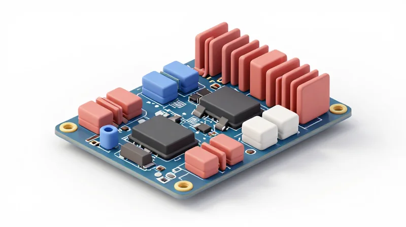
Achieving maximum thermal efficiency on an aluminum PCB (MCPCB) requires more than just high thermal conductivity dielectric layers; it demands a physical layout that treats the entire board as a cohesive heat spreader. By strategically clustering power semiconductors and optimizing the interface between the substrate and the enclosure, you can significantly lower junction temperatures and extend the lifespan of your e-bike controller.
Strategic Component Placement for Thermal Balancing
Avoid 'thermal hotspots' by spreading high-power dissipation components, such as MOSFETs, across the PCB surface. Centralizing all heat-generating components leads to localized saturation of the dielectric layer, preventing efficient heat transfer to the aluminum base. Ensure that your layout provides sufficient distance between high-side and low-side switching stages to prevent heat accumulation during high-frequency operation.
| Placement Strategy | Thermal Impact | Recommendation |
|---|---|---|
| Distributed MOSFETs | Uniform heat profile | Required for high-torque loads |
| High-current path reduction | Lower copper resistance | Maximize trace width near pads |
| Component clustering | Severe hotspots | Avoid in compact housings |
Thermal Interface Material (TIM) Selection
The bridge between your MCPCB and the aluminum chassis is the weakest thermal link. Selecting the correct TIM is essential to minimize interfacial thermal resistance.
- Why is bond-line thickness (BLT) critical?
A thinner bond-line reduces the distance heat must travel through a low-conductivity material, significantly improving total system thermal resistance. - When should I use thermal pads vs. grease?
Thermal pads are preferred for ease of assembly and electrical isolation, while high-performance phase-change materials or thermal greases offer lower contact resistance for extreme power densities. - Does the substrate surface finish matter?
Yes; ensure the aluminum base is flat (machined) to minimize air gaps, which act as insulators even when using high-performance TIMs.
Maximizing Thermal Vias and Ground Planes
In addition to the base plate, leverage the PCB copper layers. Use heavy-copper pours connected to the MOSFET thermal pads through dense arrays of thermal vias. These vias act as heat conduits, bypassing the dielectric layer's inherent resistance by providing a direct path to the aluminum core. For maximum results, specify 'filled and capped' vias to ensure solder integrity during reflow while maintaining excellent thermal conduction.
Selecting the right MCPCB substrate is the foundational step toward building a reliable, high-performance e-bike controller. By prioritizing thermal conductivity, dielectric integrity, and proper copper sizing, you can mitigate the risk of premature failure and elevate your product quality. Ready to optimize your hardware? Contact our engineering team today for a consultation on substrate selection tailored to your specific power requirements.
