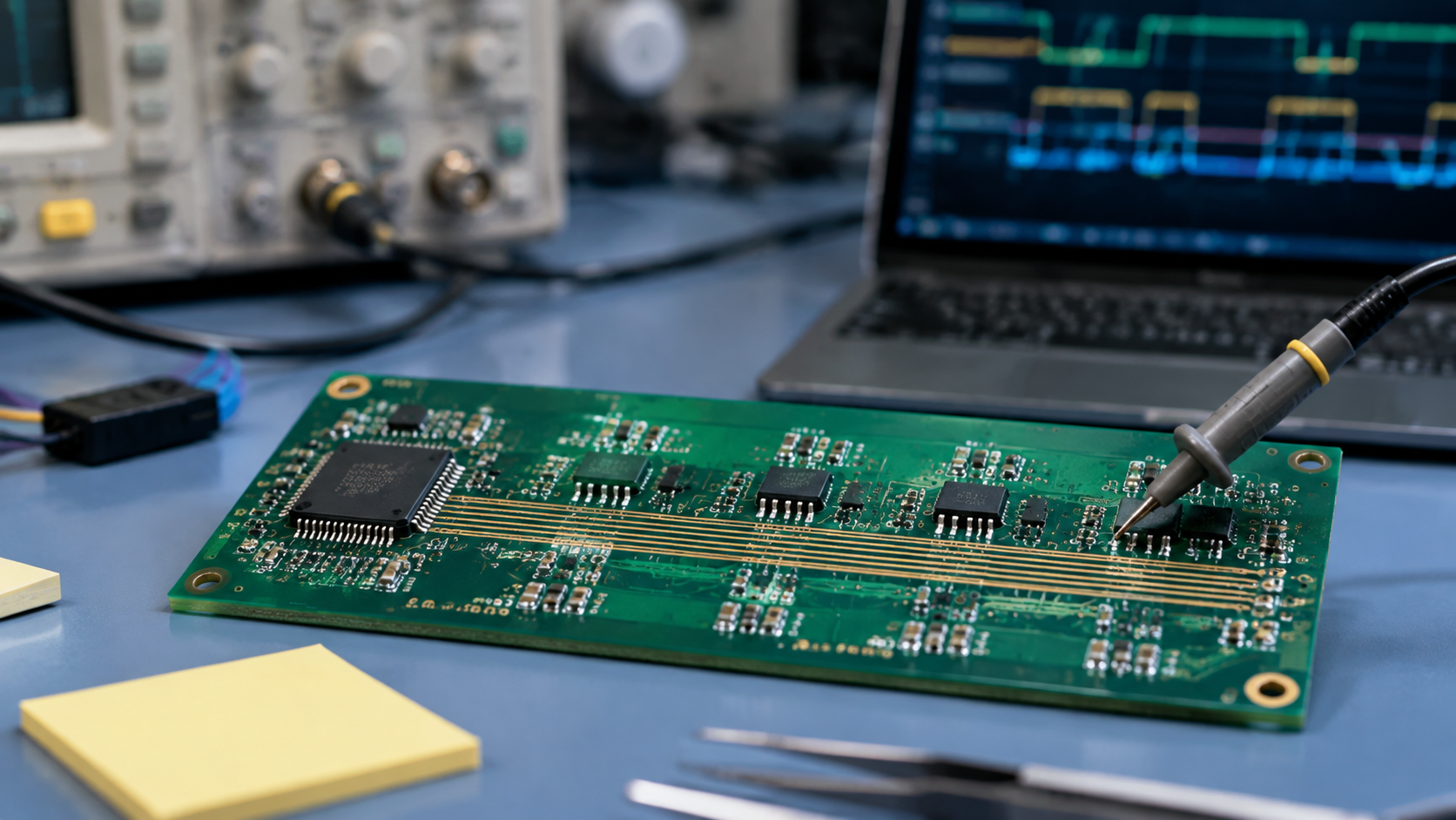
MIPI I3C (Improved Inter-Integrated Circuit) is a next-generation two-wire serial bus standard introduced by the MIPI Alliance. As a major upgrade to the traditional I2C standard, I3C retains backward compatibility with legacy I2C devices while addressing known technical challenges in multi-master operation, data rate, and power consumption.
This article provides a practical engineering overview of I3C bus technology — covering key features, operating principles, and PCB design guidelines to help hardware engineers quickly adopt this emerging bus standard.
| Feature | Description | Engineering Value |
|---|---|---|
| Dynamic Addressing | Eliminates hardware address pins; master assigns dynamic addresses automatically | Reduces pin count, simplifies hardware design |
| Hot-Joining | Supports device addition to a powered bus during operation | Enables modular design and hot-swap capability |
| In-Band Interrupt & Arbitration | No dedicated interrupt pins; built-in arbitration for multi-master conflict avoidance | Reduces pin count, simplifies bus management |
MIPI I3C is similar to traditional I2C — both use a two-wire interface to communicate with multiple peripherals on a single bus. The interface supports bidirectional half-duplex communication at significantly higher data rates than I2C.
Key development objectives of the I3C standard:
Reduce pin count on the bus
Lower power consumption through open-drain signaling
Maintain backward compatibility with legacy I2C devices
| Feature | I3C | I2C |
|---|---|---|
| Data Rate | Up to 33 Mbps | Up to 1 Mbps (Fast-mode Plus) |
| Power Efficiency | Higher efficiency via in-band interrupt and lower operating voltage | Lower efficiency compared to I3C |
| Complexity | More complex due to advanced features | Simpler design and operation |
| Backward Compatibility | Compatible with I2C devices | N/A |
| Bus Management | Advanced — dynamic addressing, hot-joining | Basic — no dynamic addressing or hot-joining |
| Error Handling | Enhanced detection and recovery | Basic error handling |
| Communication Modes | SDR, HDR, and legacy I2C modes | Traditional I2C-like modes |
Backward compatibility allows both I2C and I3C devices to coexist on the same bus. I3C supports:
Multiple I2C devices alongside standard I3C peripherals
A secondary I3C master working alongside the primary controller
Legacy I2C allows multiple controllers only if they transmit within their respective time windows. I3C, however, supports a true multi-master bus with built-in arbitration — eliminating the conflict issues found in I2C.
Typical Mixed Bus Topology: Both I2C and I3C devices are connected to the same bus. Depending on system requirements, the bus can host multiple I2C or I3C target devices, as well as secondary I3C master devices.
On the PCB, I3C uses open-drain signaling and follows similar routing practices to I2C, with specific attention to the following:
Select appropriate pull-up resistors to limit current into the open-drain driver pins. The resistor value must balance rise time and power consumption.
Bus capacitance determines the signal slew rate (rise time). For I3C, a typical rise time of approximately 100ns is acceptable, but must be adjusted based on actual bus load and clock frequency.
The physical design of an I3C bus follows standard I2C routing practices:
Keep SDA and SCL traces as short as possible
Avoid long parallel runs to minimize crosstalk
Provide a solid reference plane for critical signals
Dynamic addressing is one of I3C's three most important features, along with hot-joining and multi-master arbitration. Its primary purpose is to reduce pin count by eliminating dedicated address pins.
Dynamic Addressing Workflow:
Master sends an initial command to initiate DAA (Dynamic Address Assignment)
Unassigned devices respond with their 48-bit Provisional ID (PID)
Master assigns a dynamic address to each device based on its PID
Peripheral stores the dynamic address in its register
Because addressing is dynamic, peripheral addresses can be changed later. Legacy I2C devices connected to the I3C bus may still use static addressing.
I3C supports a process called hot-joining (hot-swap), enabling new devices to be added to the bus while it is powered and operational.
Application Example: When a module with an I3C device is plugged into a powered connector that exposes I3C bus pins, the I3C master can dynamically add the new device to the bus.
Hot-Joining Flow:
New I3C device sends a hot-join request signal to the master
Master acknowledges the new device
Master assigns an address to the new device as needed
Communication begins
MIPI I3C brings higher data rates, lower power consumption, and more flexible bus management while maintaining compatibility with I2C. Features like dynamic addressing, hot-joining, and in-band interrupt provide greater design flexibility and reduced pin count.
For PCB designers, I3C physical design is straightforward — largely following I2C routing rules while paying attention to pull-up resistors, bus capacitance, and rise time selection.
Need Support with High-Speed Bus PCB Design?
AnyPCBA has extensive experience in PCB design for high-speed digital interfaces, including I3C, I2C, SPI, USB, PCIe, and more. Our engineering team provides layout reviews and signal integrity assessments during the design phase to ensure reliable bus communication.
Contact us to discuss your project →




