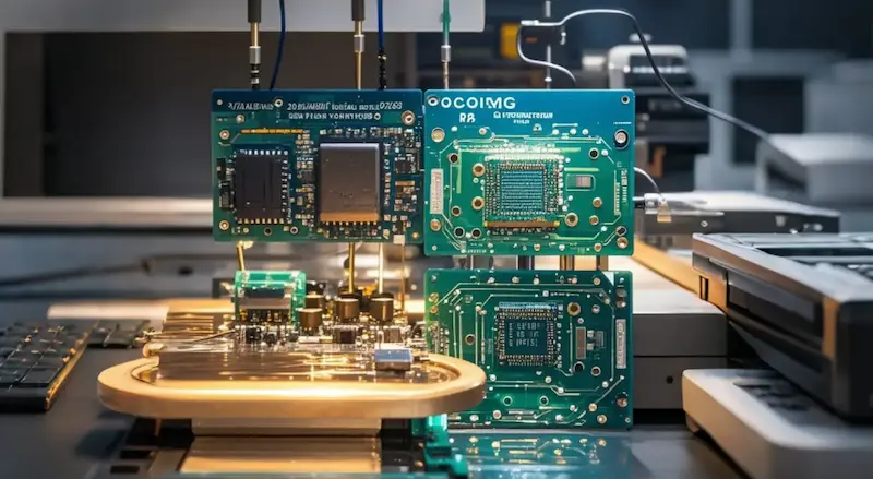
Introduction: PCB reliability directly affects the stability of electronic devices. This guide covers common PCB failure cases—short circuits, open circuits, signal transmission anomalies, board warpage, component detachment, substrate aging, and solder fatigue—along with their root causes in design, manufacturing, and environmental stress, plus practical prevention measures.
Description: Based on AnyPCBA's small-to-medium volume PCB and PCBA manufacturing experience, this guide explains common PCB failures—from electrical faults and mechanical stress to material aging and solder fatigue—their root causes, and how DFM review and process control reduce failure risk.
A printed circuit board (PCB) is a key component of electronic devices, and its reliability directly affects overall performance and stability. During PCB production, use, and maintenance, various failures can occur and disrupt normal operation.
Understanding common PCB failure cases and their causes is essential for improving PCB quality and ensuring stable device operation. This article organizes PCB failures into three categories—electrical, mechanical, and material—with root causes from a manufacturing perspective.
Case: A smartphone motherboard frequently crashed and overheated. Inspection revealed fine copper residue bridging adjacent traces on the PCB.
Manufacturing cause: Improper etching control left excess copper, creating a short circuit during use.
Assembly cause: Excessive solder during component soldering flowed onto adjacent traces.
Prevention: Strict etching parameter control and 100% AOI inspection before shipment; solder paste volume and stencil aperture control during SMT.
Case: An industrial control device lost its control signal. Inspection found a crack in a PCB trace that gradually expanded until the circuit completely opened.
Mechanical stress cause: Severe vibration during transport caused trace cracking.
Environmental cause: Temperature changes and humidity caused trace oxidation and corrosion over time.
Prevention: Widen traces or use teardrop pads in stress-prone areas; apply conformal coating for harsh environments.
Case: A 5G base station experienced unstable signal transmission and packet loss. Inspection found excessively long signal traces without proper impedance matching.
Design cause: Long high-speed traces caused signal attenuation and reflection; electromagnetic interference was not properly shielded.
Prevention: Calculate impedance strictly during DFM review, enforce length matching, and add ground shielding beside high-speed signals.
Case: A laptop displayed screen artifacts and unstable operation. Inspection found the motherboard PCB had warped, loosening component connections.
Use-side cause: Repeated external pressure (tight spaces or heavy objects).
Manufacturing cause: Improper lamination control with uneven pressure between layers caused deformation during use.
Prevention: Confirm symmetrical stack-up design during DFM review; strictly control lamination parameters and cooling rates.
Case: An automotive engine control unit raised a fault alarm after some time in use. Inspection found a critical component had detached from the PCB.
Mechanical stress cause: Strong vibration and shock during vehicle operation gradually loosened the solder joint.
Soldering cause: Soldering temperature too low or time too short resulted in insufficient joint strength.
Prevention: Optimize reflow profiles to ensure proper wetting; apply underfill/adhesive for heavy components after SMT.
Case: A server frequently crashed and lost data after years of operation. Inspection found the substrate material had aged.
High-temperature cause: Long-term operation at elevated temperatures decomposed the resin in the substrate, degrading electrical and mechanical performance.
Environmental cause: UV exposure and chemicals accelerated aging.
Prevention: Use high-Tg laminates for high-temperature applications; add protective coatings for outdoor equipment.
Case: During repair of an electronic product, solder joints were found cracked and loose. Analysis showed solder fatigue.
Material cause: Low-quality solder with non-compliant composition reduced joint strength and reliability.
Thermal stress cause: Frequent temperature changes subjected joints to thermal stress; long-term fatigue caused cracking and loosening.
Prevention: Use high-quality lead-free solder (such as SAC305); consider CTE matching at the design stage.
AnyPCBA places strong emphasis on PCB quality control. Our manufacturing capabilities cover 2 to 64 layers, including HDI, rigid-flex, and high-frequency hybrid. We hold ISO 13485 (medical) and IATF 16949 (automotive) certifications.
To reduce the failure risks described above, we take the following measures:
Optimized design review: During DFM review, engineers check trace width, spacing, impedance matching, and stack-up symmetry to prevent short circuits, open circuits, and warpage at the source.
Strict process control: Critical processes such as etching, lamination, drilling, and plating are strictly monitored to ensure every step meets standards.
High-quality materials: Laminates and solder are strictly screened, with quality checks from raw material procurement to finished product inspection.
Comprehensive quality inspection: AOI, X-Ray, and flying probe testing are used to ensure every PCB meets high reliability and stability requirements.
If you're troubleshooting a PCB failure, or want to learn more about our quality control process, contact us through our website.