In the realm of electronics prototyping, perfboard, also known as a prototyping board or dot PCB, serves as a versatile canvas for bringing your circuits to life. Unlike the predefined connections of breadboards or stripboards, perfboard offers the freedom to create custom layouts, paving the way for a wide array of DIY projects and intricate designs. This guide dives into the world of perfboard, from understanding its basic structure to mastering advanced techniques, providing a detailed roadmap to navigate and utilize perfboard effectively.
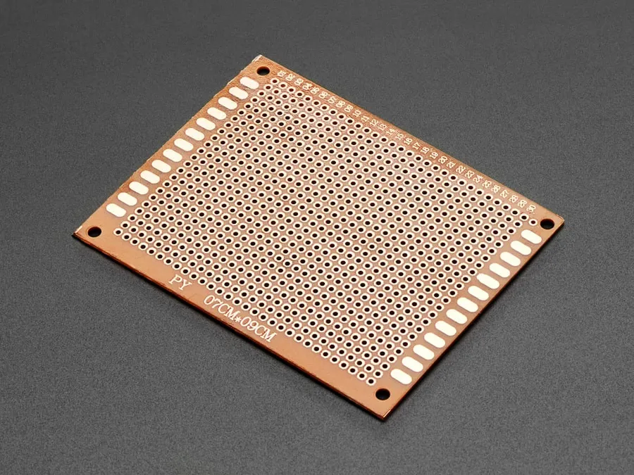
Perfboard, also known as prototyping board, is a fundamental building block in electronics prototyping, characterized by its grid of holes and lack of pre-defined conductive pathways, offering a flexible platform for constructing circuits. Unlike breadboards, perfboard requires permanent connections, typically achieved through soldering.
Perfboard's structure is simple yet versatile, primarily consisting of a substrate, typically made from materials like phenolic, fiberglass, or bakelite. These materials are chosen for their electrical insulating properties and mechanical strength. The surface is uniformly punctuated with a matrix of holes, usually spaced 0.1 inches (2.54 mm) apart to accommodate standard electronic components. These holes lack internal electrical connections, allowing designers to create custom circuits by connecting components with solder and wire.
Variations in perfboard cater to diverse project needs. Hole diameters are generally standardized, but board sizes range from small, hand-held pieces to large panels for extensive projects. Pad styles vary from simple through-holes to pads with surrounding copper rings (also called plated through-holes or PTH), facilitating improved solder adhesion and joint strength, whilst minimizing the risk of pad lifting.
| Characteristic | Description |
|---|---|
| Material Composition | Typically phenolic, fiberglass, or bakelite. |
| Hole Grid | Uniform matrix of holes, usually spaced 0.1 inch (2.54mm) apart. |
| Electrical Connections | No pre-defined connections; custom connections created by soldering. |
| Hole Size | Standardized diameter (approximately 0.04 inch or 1mm), to fit typical component leads. |
| Board Size | Available in various sizes, from small to large panels. |
| Pad Styles | Options include basic through-holes or plated through-holes (PTH) with surrounding copper rings. |
Breadboards and perfboards serve distinct purposes in electronics prototyping, with breadboards offering temporary, solderless connections ideal for rapid circuit testing, while perfboards provide a more permanent and flexible solution using soldering for more robust builds. This fundamental difference in connection methods dictates their appropriate use cases.
| Feature | Breadboard | Perfboard |
|---|---|---|
| Connection Type | Solderless | Soldered |
| Permanence | Temporary | Permanent |
| Flexibility | Limited to predefined rows and columns | Highly flexible in component placement and wiring |
| Ease of Modification | Easy to change and modify | Requires desoldering for changes |
| Durability | Suitable for temporary tests, less durable for long term usage | Durable for long term builds and better for rugged applications |
| Best Use Case | Quick testing and prototyping of basic circuits | More complex and robust builds, projects needing a permanent assembly |
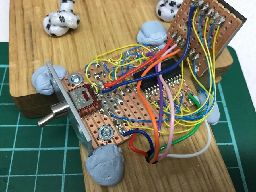
Selecting the appropriate prototyping platform—perfboard, breadboard, or stripboard—is crucial for efficient electronics development. Each offers unique characteristics that suit different project requirements. This section provides a detailed comparison to help you make informed choices.
| Feature | Perfboard | Breadboard | Stripboard |
|---|---|---|---|
| Connection Method | Soldered | Solderless | Soldered (typically) |
| Connection Structure | Isolated Holes | Internal Connected Rows & Columns | Parallel Tracks of Holes |
| Permanence | Permanent | Temporary | Semi-permanent |
| Flexibility | High (flexible layout) | Low (fixed layout) | Moderate (limited track layout) |
| Ease of Use | Moderate (requires soldering) | High (quick and easy) | Moderate (requires track cutting) |
| Complexity Handling | Handles complex circuits well with careful planning. | Limited to simpler circuits, can become difficult with complex wiring | Suited for medium-complexity circuits, requires planning |
| Best for | Permanent prototypes, custom layouts. | Quick testing, temporary circuits. | Medium-complexity circuits that require some permanence. |
Breadboards excel in providing a solderless environment for rapid prototyping and testing. Their internal, interconnected rows and columns allow for easy component insertion and circuit construction. Conversely, perfboards utilize a grid of isolated holes, which require soldering to create electrical connections. This makes perfboard a more permanent solution compared to the breadboard's temporary nature. Breadboards are ideal for initial circuit exploration and quick modifications, while perfboards are better suited for building more robust, enduring prototypes.
Stripboards feature pre-connected tracks of holes, which facilitates rapid prototyping and is suitable for circuits that follow a more linear design. These tracks can be easily cut, providing moderate flexibility, but are not as free-form as perfboard. Perfboards, with their isolated holes, demand point-to-point wiring or the use of jumpers to make connections between components. Perfboard offers maximum layout flexibility, where component placement is not dictated by existing tracks. Stripboards are better suited for circuits that align with their track structure, while perfboards are optimal for custom layouts and more complex connections, especially when point-to-point wiring is used effectively.
Perfboard and stripboard represent distinct approaches to prototyping electronics, primarily differing in their connection methods. While perfboard provides isolated holes requiring manual wiring for each connection, stripboard features pre-etched copper tracks, creating connected rows of holes. Understanding these differences is crucial for choosing the right board for your project, as they impact flexibility, ease of assembly, and the overall design of the circuit.
| Feature | Perfboard | Stripboard |
|---|---|---|
| Hole Connectivity | Isolated Holes | Connected Rows/Tracks |
| Wiring | Point-to-point or wire wrapping | Connections along tracks and jumpers |
| Flexibility | Highly flexible in routing | Less flexible in routing, requires planning |
| Ease of Use | More time consuming, requires planning and wiring | Easier for basic circuits, faster assembly |
| Best for | Complex or custom layouts | Simpler circuits with linear layouts |
| Component Placement | Can place components anywhere | Restricted to track layout |
Stripboard excels in situations where components can be easily aligned along the tracks. This is particularly useful for basic circuits or when a linear layout is suitable. However, the pre-defined tracks of stripboard can also limit flexibility and may require additional cutting of tracks to break connections and more planning to ensure no unintended shorts occur. Perfboard, with its isolated holes, allows for more intricate, free-form layouts, making it the preferred option for complex circuits with more customized connections. However this requires more point to point wiring which can be more time consuming and more prone to errors.
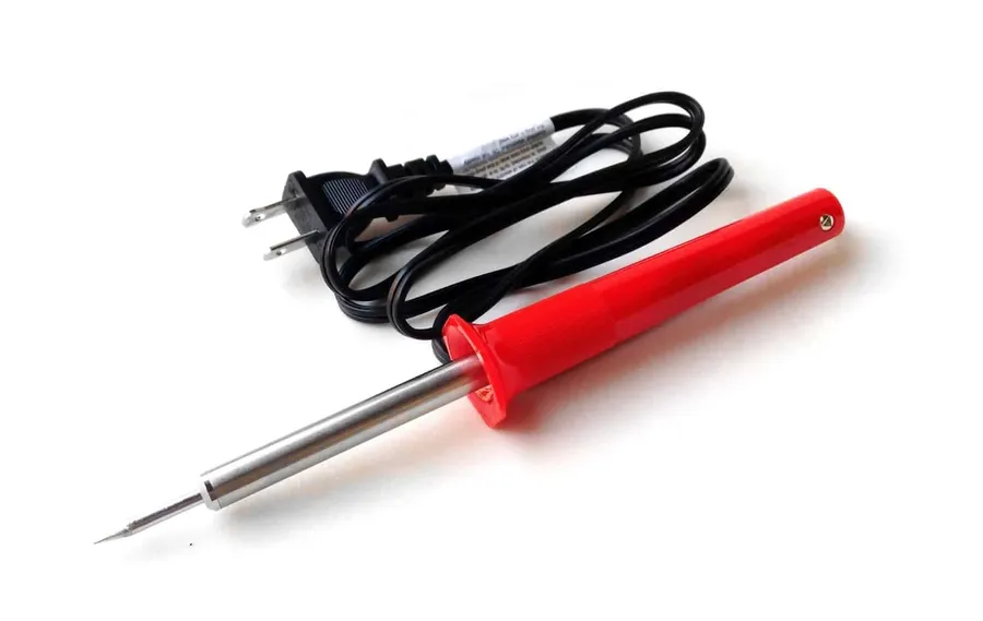
Successfully building electronics projects on perfboard requires a selection of specialized tools and materials. This section outlines the essential items, focusing on their selection and usage for optimal results, ensuring a beginner-friendly approach while maintaining professional standards.
| Tool/Material | Description | Selection Considerations | Beginner Tips |
|---|---|---|---|
| Soldering Iron | Heats solder to create electrical connections. | Adjustable temperature, fine tip for precision, wattage suitable for electronics (25-40W). | Practice on scrap material, clean the tip regularly, use a stand for safety. |
| Solder | Metal alloy used to join electronic components. | Lead-free solder preferred, 60/40 tin/lead for beginners (note lead content), rosin core for flux. | Use a small amount of solder, avoid creating large blobs, let the solder flow onto the joint. |
| Wire Strippers | Removes insulation from wires without damaging the conductor. | Adjustable gauge settings, comfortable grip, sharp cutting blades. | Match the gauge setting to the wire, gently squeeze to cut, avoid cutting the wire strands. |
| Wire (Solid core) | Connects components, typically 22-26 AWG for perfboard. | Solid core for reliable connections, insulated, various colors for organization. | Use appropriate gauge for current, plan wiring routes to minimize clutter, choose colors that aid circuit tracing. |
| Helping Hands | Provides stability while soldering. | Adjustable arms and clips, sturdy base. | Use to hold the board and components while soldering, position for easy access. |
| Multimeter | Measures voltage, current, and resistance. | Digital display, autoranging, continuity test function. | Learn basic measurement techniques, use to check for shorts and open circuits, verify component values. |
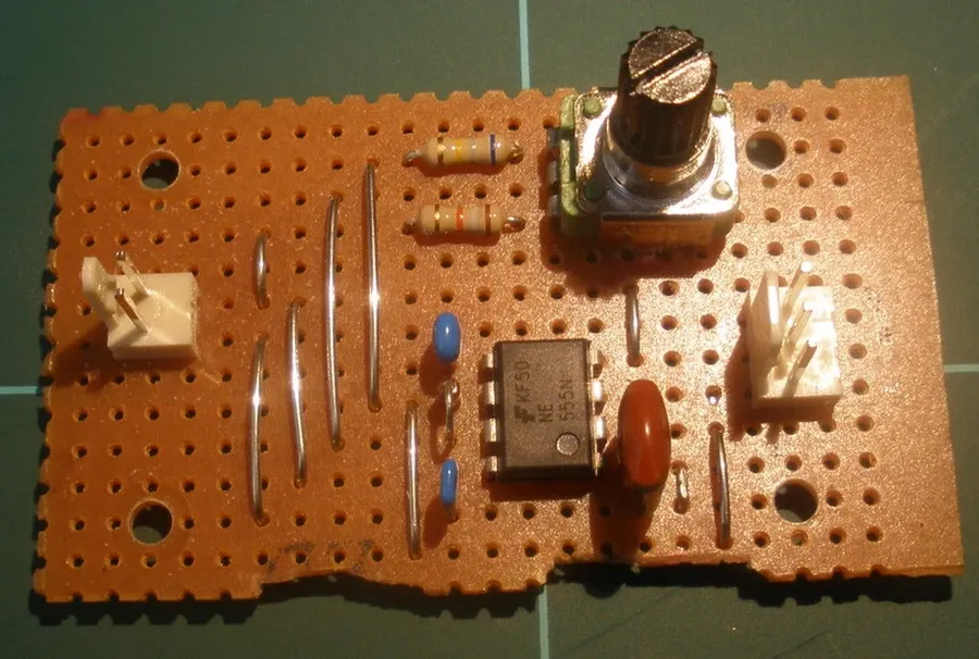
Effective perfboard projects hinge on meticulous planning before any soldering begins. A well-thought-out layout significantly reduces the likelihood of errors, simplifies debugging, and ensures a robust final circuit. This section outlines essential best practices for planning your perfboard layout.
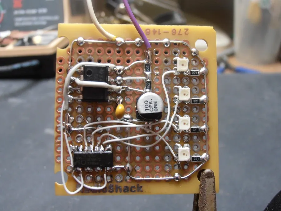
Mastering soldering on perfboard is crucial for creating durable and reliable electronic prototypes. This section delves into techniques that ensure strong, electrically sound connections while avoiding common pitfalls.
Effective soldering on perfboard requires precision, proper equipment, and a clear understanding of the process. The following will help you ensure your components and circuits are attached correctly. Key to success are three points, preparation, process and post-soldering checks.
| Technique | Description | Benefit | Common Pitfall |
|---|---|---|---|
| Standard Soldering | Heating the pad and component lead, then applying solder to the heated junction. | Strong and electrically sound joint. | Cold solder joints if not heated properly, solder bridges if too much solder is applied. |
| Drag Soldering | Apply solder to the iron tip, and drag across multiple points. | Faster for multiple connections | Difficult to control solder application and risk of short circuits. |
| Through Hole Soldering | Insert component lead through hole, then solder on the pad | Secure, suitable for larger components. | Risk of overheating the lead or pad and damaging components or the board. |
Specific solder recommendations for perfboard projects typically include lead-based solder with a rosin core (e.g., 60/40 Sn/Pb), as it offers lower melting point, and good conductivity while being easy to work with. Lead-free alternatives, like SnAgCu alloys, are also increasingly common, although their slightly higher melting points may require adjustments in soldering technique. Flux is key, both lead and lead-free solders should include a rosin flux core, this will promote flow and create better joints. Select the gauge or diameter of the solder wire appropriately for perfboard work, 0.8mm or less is usually best for precise applications and reducing solder bridging.
By applying these techniques, you will improve the strength and reliability of your perfboard projects, minimise common soldering errors, and ensure good electrical connections. Regular practice and careful attention to detail are key to becoming proficient at soldering.
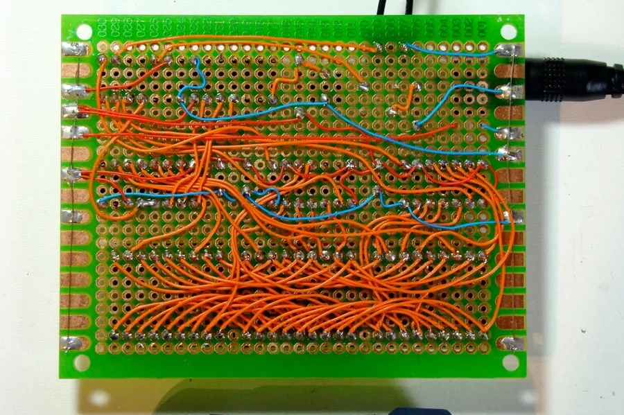
Effective wiring and connection techniques on perfboard are crucial for project functionality, signal integrity, and overall neatness. Proper methods ensure reliable electrical paths and ease of debugging, moving from prototyping to stable circuits. Various methods exist, each with advantages and disadvantages depending on the complexity and requirements of the electronic project.
Here are some of the most common techniques:
For managing wiring effectively, consider these best practices:
This section addresses common queries regarding perfboard, providing concise answers to help you effectively use this versatile prototyping tool. We cover topics ranging from its basic comparisons with other boards to specific usage questions.
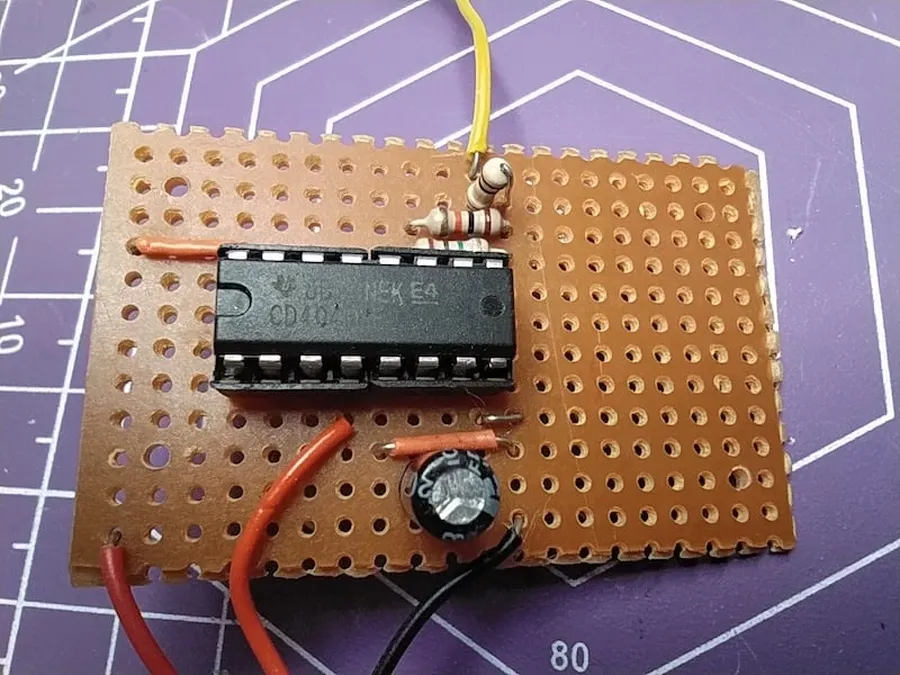
Mastering perfboard for complex electronics projects requires advanced techniques beyond basic soldering and wiring. This section focuses on multi-layer designs, working with surface-mount components (SMD), systematic troubleshooting, and employing a multimeter effectively. Understanding these methods elevates your perfboard proficiency, enabling robust and reliable circuit construction.
By adopting these advanced techniques and employing thorough troubleshooting methods, you will be able to effectively build robust and complex circuits on perfboard. These skills are essential to advance from beginner projects to more complicated designs.
Perfboard stands as an essential tool in the electronics enthusiast's arsenal, providing the flexibility for creating custom circuits while bridging the gap between temporary prototypes and permanent builds. Whether you are a beginner experimenting with basic circuits or an experienced maker tackling complex projects, understanding the nuances of perfboard is key to taking your designs to the next level. The tips and techniques discussed in this comprehensive guide, from proper planning and soldering to advanced layout methods, ensure that you can confidently start, and debug your perfboard projects with efficiency. As you continue to learn and refine your skills, perfboard will transform from a simple prototyping tool into a powerful instrument for your electronic innovations and beyond.

