Mastering Rigid-Flex PCBs: Design, Applications, and Manufacturing
2025.01.28
In today's fast-paced world of electronics, where miniaturization and flexibility are key, the rigid flex PCB stands as a marvel of engineering. Imagine a circuit board that can bend and conform to complex shapes, eliminating the need for bulky connectors and cables. This isn't science fiction; it's the reality of rigid flex PCB technology, seamlessly integrating rigid and flexible circuit sections. This article dives deep into the design, manufacturing, and application of rigid flex PCBs, guiding you through their intricacies and showcasing how they are revolutionizing industries from aerospace to consumer electronics.
Understanding Rigid-Flex PCB Basics
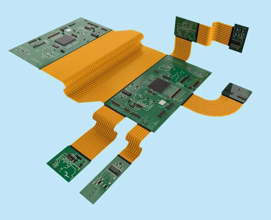
Rigid-Flex PCB
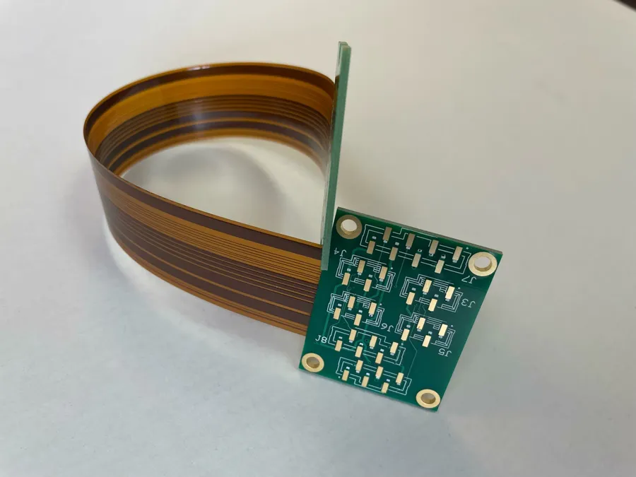
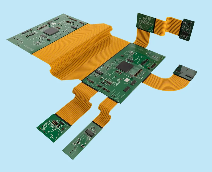
Rigid-flex PCBs represent a sophisticated integration of rigid and flexible circuit board technologies, combining the robustness of rigid boards with the adaptability of flexible circuits into a single, seamless structure, which is a pivotal advancement in electronics design, offering enhanced reliability and design versatility.
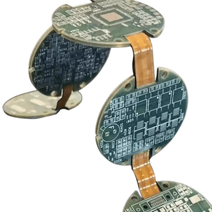
At their core, rigid-flex PCBs address the limitations of using separate rigid boards interconnected by cables or connectors. This integrated approach provides a significant reduction in the number of interconnects, thereby enhancing overall system reliability and simplifying assembly processes. By incorporating both rigid and flexible sections, designers gain the advantage of placing components on the rigid areas, leveraging the structural support, while the flexible sections allow for dynamic bending, twisting, and three-dimensional configurations. This results in complex device design within confined spaces.
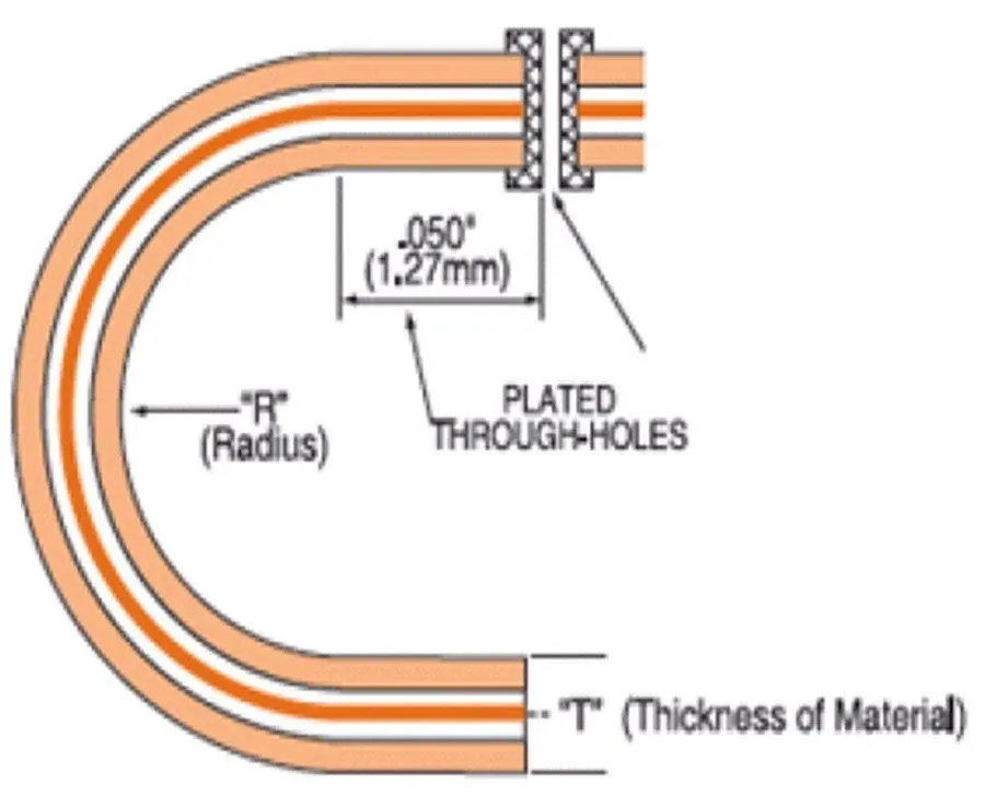
Functionally, rigid-flex PCBs maintain electrical continuity between rigid and flexible areas through plated through-holes and vias that extend across both types of material, ensuring signal integrity and stable electrical performance. The construction of these PCBs involves precision manufacturing techniques that include lamination, etching, and plating, performed with specialized materials tailored for the different performance requirements of each area. This unique combination enables the creation of highly compact, reliable, and efficient electronic devices.
Advantages of Rigid-Flex PCBs
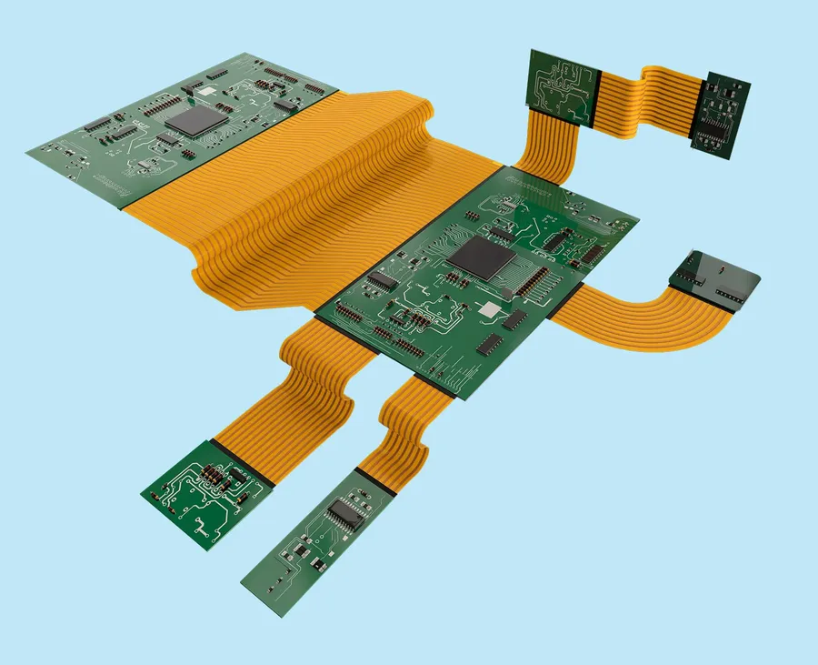
Rigid-Flex PCB with Connector
Rigid-flex PCBs offer a compelling array of advantages over traditional rigid PCBs and flexible circuits, primarily stemming from their unique ability to combine the structural integrity of rigid boards with the flexibility of flexible circuits. This integration results in solutions that are not only more compact and reliable, but also offer superior design freedom and potential cost savings in assembly.
Advantage
Rigid-Flex PCB
Traditional PCB
Flexible PCB
Space Savings
High (Integration minimizes space)
Low (Requires connectors and cabling)
Moderate (Can conform to shapes, but may need support)
Reliability
High (Reduced interconnections)
Moderate (Subject to connector failure)
Moderate (Sensitive to handling, requires additional support in some cases)
Design Flexibility
High (Complex 3D geometries)
Low (Limited to flat planes)
High (Can bend and flex, but require careful design)
Assembly Costs
Potentially Lower (Fewer connections and parts)
Higher (Numerous connectors and parts)
Moderate (Potential cost savings from reduced parts, but may require additional fixturing )
Signal Integrity
High (Minimized signal path lengths)
Moderate (Signal degradation through connections)
Moderate (Signal degradation due to flexibility)
Weight
Low (Integration reduces bulk)
High (Connectors, cables add weight)
Low (Lightweight, but needs support in some cases)
Space Optimization: Rigid-flex PCBs allow for dense component placement in the rigid sections while utilizing the flexible sections for routing and interconnects, thereby maximizing space utilization and enabling smaller form factors.
Enhanced Reliability: By integrating rigid and flexible circuits into a single unit, rigid-flex PCBs eliminate the need for connectors and wiring, which are common failure points in traditional PCB assemblies. This reduces potential points of failure and increases the overall reliability of the system. The reduction in interconnects not only reduces potential failure points but also improves signal integrity.
Design Versatility: The ability to bend and fold the flexible portions of the board allows for complex 3D designs that are not possible with traditional rigid PCBs. This enables greater flexibility in product design and facilitates innovative solutions.
Reduced Assembly Costs: With fewer parts and connections to manage, the assembly process for rigid-flex PCBs is often simpler and faster than that for traditional PCBs connected by flex cables and connectors. This reduction in complexity can lead to significant cost savings in manufacturing.
Improved Signal Integrity: The direct interconnection between rigid and flex portions minimizes the need for connectors and wiring. This results in shorter signal paths, which reduces signal degradation, reflections, and electromagnetic interference (EMI). The result is often higher signal quality and performance.
Lightweight Design: The combination of rigid and flexible sections often results in a reduction in overall weight, as compared to traditional interconnect methods using connectors and cables. This lightweight design is advantageous in applications where weight is a critical consideration, such as in aerospace and portable devices.
Challenges and Considerations of Rigid-Flex PCBs
Bent Rigid-Flex PCB
While rigid-flex PCBs offer numerous advantages, their design and manufacturing introduce a unique set of challenges that must be carefully considered. These challenges span material selection, fabrication complexities, and cost implications, demanding specialized expertise and meticulous planning.
Material Selection Choosing the correct materials for both the rigid and flexible portions is critical for performance and reliability. Factors like thermal expansion coefficients, flexural strength, and chemical resistance must be carefully evaluated to ensure compatibility and longevity. The transition between different materials at the rigid-flex interface can cause stress concentrations.
Fabrication Complexity The manufacturing process of rigid-flex PCBs is significantly more complex than that of standard rigid PCBs. It involves combining multiple lamination steps, precise registration, and controlled depth drilling to accommodate the combination of rigid and flexible materials. This complexity increases the risk of manufacturing errors, requiring rigorous quality control at each stage.
Cost Implications Due to the added complexity in material handling, design, and manufacturing, rigid-flex PCBs generally have higher production costs compared to their rigid counterparts. The higher costs stem from factors such as specialized equipment, skilled labor, lower yields, and higher material costs. Proper design optimization is essential to minimize overall cost while maintaining performance.
Design Constraints Rigid-flex design presents additional constraints, including bend radii limitations, routing restrictions in the flexible area, and the need for specific techniques to accommodate dynamic flexing. Careful consideration must be given to component placement near flex areas, material stress during bending, and overall signal integrity. Improper design can lead to structural failures, and signal degradation.
Testing and Inspection Testing rigid-flex PCBs requires specialized fixtures and procedures, as standard PCB testing setups are often inadequate due to the flexibility of certain board sections. Comprehensive inspection is crucial to identify potential manufacturing defects and design flaws early in the process.
Assembly Process Assembling components on rigid-flex boards can be more complicated compared to traditional PCBs. Careful handling and specialized assembly methods are needed to prevent damage to the flexible sections. Automated assembly may be limited due to the 3D nature of the boards.
Rigid-Flex PCB Material Stack-Up and Layer Configurations
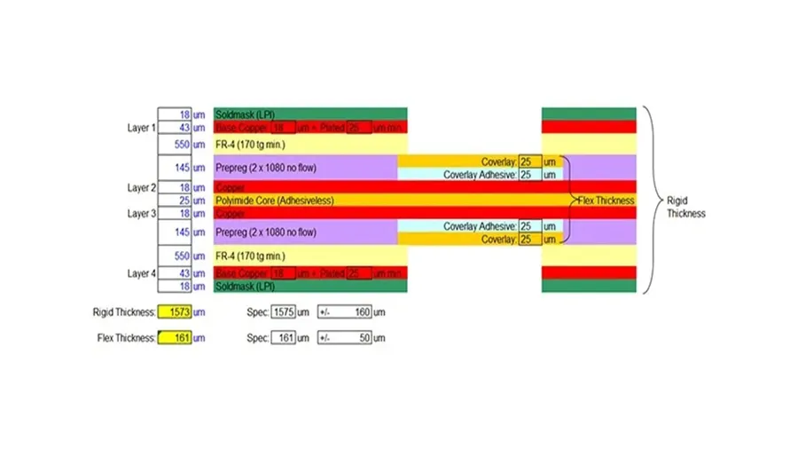
Rigid-Flex PCB Layer Stack-Up
The performance and reliability of rigid-flex PCBs are significantly influenced by the choice of materials and layer configurations. These PCBs combine rigid and flexible substrates, each requiring specific material properties to ensure optimal functionality. Understanding the material stack-up and layer arrangements is crucial for design and manufacturing success.
Material Type
Description
Typical Applications
Advantages
Disadvantages
Polyimide (PI)
A flexible polymer used in the flexible sections of the PCB.
Excellent electrical and mechanical properties, high temperature resistance, good chemical resistance, dimensional stability, flexible.
Higher cost compared to other flexible materials, can be more challenging to process, moisture absorption.
FR-4
A rigid substrate material composed of woven fiberglass cloth with epoxy resin.
General purpose PCBs
Cost-effective, high strength-to-weight ratio, good insulation properties, readily available.
Not flexible, lower temperature resistance, susceptible to moisture.
Adhesive
Used to bond flexible and rigid layers together. Acrylic and epoxy based adhesives are common.
Rigid-flex PCB bonding
Provides a strong bond between layers, provides electrical insulation.
Can be temperature sensitive, must be compatible with other materials.
Copper
Used for conductive traces in both rigid and flex layers.
All PCB interconnects
Excellent conductivity, widely used and readily available, good solderability.
Can oxidize, susceptible to corrosion, is a soft metal.
Layer configurations in rigid-flex PCBs are complex, requiring careful planning to optimize signal integrity and manufacturability. A typical stack-up includes multiple layers of flexible and rigid materials, with specific material thicknesses and arrangements. The flexible layers are often placed in areas requiring bending or dynamic movement, while the rigid sections provide support and mounting points for components.
Rigid-Flex PCB Design Guidelines
Rigid-Flex PCB Layout
Effective rigid-flex PCB design hinges on adhering to specific guidelines that consider both the rigid and flexible sections. These guidelines are crucial for ensuring manufacturability, reliability, and optimal performance of the final product, encompassing impedance control, bending radii, and component placement strategies.
Designing for manufacturability (DFM) is paramount in rigid-flex PCB design. This involves careful consideration of material limitations, assembly tolerances, and the intricacies of the fabrication process. Improper design can lead to manufacturing defects, increased costs, and ultimately, a non-functional product. Therefore, integrating DFM principles from the initial stages is essential.
Impedance Control Maintaining consistent impedance is crucial for signal integrity in high-speed applications. This requires precise control over trace widths, spacing, and dielectric material properties in both rigid and flexible regions. Consider using impedance calculators and simulation tools to verify your design.
Bending Radius The flexible sections must adhere to specific minimum bending radii to prevent material stress and damage. The bend radius is usually dependent on material type and thickness, with manufacturer specifications being key. It's generally advised to use the maximum radius possible for each bend.
Component Placement Avoid placing components on the flex sections of the PCB, especially close to bend points, as this will result in reduced flexibility and increased potential for damage during flexing. Components should be located on rigid sections of the board. Ensure that connectors, which might be necessary for connection between rigid sections, are specified to be robust enough to manage the mechanical stresses and movements in a rigid-flex structure.
Layer Transitions Layer transitions between rigid and flexible sections must be carefully planned to minimize stress concentrations. Avoid sharp, right-angle transitions, instead using smooth, gradual transitions. Ensure that the transition areas have the correct material and layer stackup to support movement and reduce the risk of fractures.
Via Design Vias at the rigid-flex transition zones are high-stress areas; therefore, they require careful design. Use tear-drop vias or reinforced vias to enhance their mechanical stability and prevent cracking or fractures. Avoid placing vias on or near bend areas.
Material Selection Material selection impacts flexibility, performance, and cost. Choose appropriate materials for both rigid and flexible parts based on performance requirements, environmental conditions, and budget. It is advisable to work with your chosen manufacturer to select the most appropriate materials.
Panelization Panelization and array design are essential for rigid-flex PCBs. Ensure that the design works correctly for production and minimizes material wastage. Ensure that the design allows for ease of component assembly and separation of the individual boards once fabrication is complete.
Manufacturing Processes for Rigid-Flex PCBs
Rigid-Flex PCB Manufacturing
The manufacturing of rigid-flex PCBs involves a complex series of steps that combine techniques used for both rigid and flexible circuit board fabrication. This process necessitates precise control and specialized equipment to ensure the reliable integration of rigid and flexible sections, which is crucial for the final product's performance and longevity.
The manufacturing process flow is as follows:
Material Preparation: This initial stage involves selecting and preparing the necessary materials, such as the rigid core material (FR-4, polyimide, etc.), flexible polyimide films, and copper cladding. Precise cutting and cleaning of these materials are essential to ensure optimal adhesion and performance in subsequent processes.
Inner Layer Fabrication: This step is similar to the standard PCB production. The rigid core's inner layers are imaged, etched, and treated to establish the conductive patterns on the board.
Flexible Layer Processing: The flexible polyimide film undergoes its own imaging and etching process to create the conductive circuitry necessary for the flexible portions of the board. Precision during this stage is critical to meet the necessary dimensional and functional requirements.
Lamination: This critical step involves the precise lamination of the rigid and flexible layers. Specialized bonding materials and controlled pressure and temperature cycles are employed to ensure a strong and durable bond between the different materials. The use of lamination is crucial to prevent air gaps and delamination in the final product.
Drilling: Following lamination, the circuit board undergoes drilling. This process forms vias and plated through-holes (PTH), which connect the different layers of the rigid-flex board. It is essential to use specialized drilling machines to ensure the precise drilling of different materials with varying mechanical properties.
Plating: After drilling, the drilled holes and surface features are plated with copper to provide electrical connectivity. The plating process requires precise chemical control to ensure uniform metallization and reliable electrical connections.
Outer Layer Imaging: The external layers are imaged and etched, revealing the circuit pattern.
Surface Finishing: The PCB is finished with a protective surface finish, such as ENIG (Electroless Nickel Immersion Gold) or HASL (Hot Air Solder Leveling), to ensure solderability and corrosion resistance.
Cutting and Profiling: The final step involves cutting and profiling the rigid-flex board to its final dimensions using precision laser or mechanical cutting systems. This stage is crucial to ensure the board fits perfectly into the final assembly.
Quality Control: Throughout the manufacturing process, rigorous quality control checks are performed using techniques such as automated optical inspection (AOI) and electrical testing. This quality control process ensures the final product meets all design specifications and performance requirements.
Specialized Techniques for Rigid-Flex Boards include:
Controlled Depth Routing (CDR): This technique is essential for creating precise boundaries between the rigid and flexible sections and to control the mechanical and bending properties of the board.
Specialized Lamination: The lamination process uses low-flow bonding materials and is performed under very controlled conditions to prevent delamination issues.
Flex-Specific Drilling and Plating: These processes are optimized for handling the flexible substrates, ensuring proper plated through-hole (PTH) connections.
Applications of Rigid-Flex PCBs
Rigid-Flex PCB in Camera
Rigid-flex PCBs, with their unique blend of rigid and flexible circuit board technologies, enable innovative solutions across a multitude of industries. Their ability to conform to complex shapes, reduce overall system size, and enhance reliability makes them indispensable in applications where traditional PCBs fall short. The following sections will highlight some of the key applications and explain the specific advantages they offer.
Aerospace In aerospace, rigid-flex PCBs are crucial for avionics systems, satellite components, and control systems. Their lightweight nature and ability to withstand harsh environments are essential. For example, in aircraft control panels, they minimize weight while ensuring reliable data transmission across complex shapes.
Medical Devices Medical devices benefit greatly from rigid-flex PCBs due to their compact size, high reliability, and ability to fit into intricate geometries. They are found in implantable devices, diagnostic equipment, and patient monitoring systems. The flexibility allows them to conform to body contours and allows for complex routing within small medical devices, thus improving patient comfort and device functionality.
Automotive The automotive industry utilizes rigid-flex PCBs in applications such as advanced driver-assistance systems (ADAS), infotainment systems, and engine control units (ECUs). Their ability to withstand vibration and extreme temperatures makes them ideal for automotive environments. Specifically, they contribute to reducing weight and space within vehicles, allowing for more integrated electronics.
Consumer Electronics Consumer electronics, including smartphones, wearables, and cameras, leverage rigid-flex PCBs for their compact size and design flexibility. The ability to fold and flex these boards is critical for achieving slim, feature-rich devices. For instance, the hinge mechanisms in foldable phones or the compact designs in smartwatches directly benefit from the use of rigid-flex technology.
Industrial Equipment Rigid-flex PCBs are also utilized in industrial equipment, where reliability and ruggedness are essential. Applications include robotics, industrial control systems, and testing equipment. These boards are crucial in environments that subject the equipment to severe mechanical stress and extreme conditions where they provide an effective way to connect different segments of a device.
Industry
Application Examples
Unique Benefits
Aerospace
Avionics, Satellite Systems, Control Panels
Lightweight, High Reliability, Durability
Medical Devices
Implantables, Diagnostics, Patient Monitoring
Compact Design, Biocompatible, Complex Geometries
Automotive
ADAS, Infotainment, ECUs
Vibration Resistance, High Temperature Tolerance, Reduced Weight
This section addresses common inquiries regarding rigid-flex PCBs, clarifying their distinctions from flexible PCBs, examining cost factors, and exploring future trends. We aim to provide clear and concise answers to help you better understand these versatile circuit boards.
What is the core difference between a flex PCB and a rigid-flex PCB? A flex PCB is entirely flexible, designed to bend and conform to various shapes. In contrast, a rigid-flex PCB combines both rigid and flexible circuit board sections in a single integrated structure. The flexible portions allow for bending, while the rigid parts provide support for components.
How do the terms 'flex PCB' and 'FPC' relate to each other? The terms 'flex PCB' and 'FPC' (Flexible Printed Circuit) are often used interchangeably, generally referring to the same type of entirely flexible circuit boards. Therefore, there is effectively no practical difference between them in common usage.
What are the main drawbacks or disadvantages of using rigid-flex PCBs? The primary disadvantages of rigid-flex PCBs include higher manufacturing costs compared to standard PCBs and more complex fabrication processes. These factors can lead to longer lead times and potentially lower yield rates, requiring careful design and planning. Additionally, material selection and the interconnection of rigid and flexible sections require specialized expertise.
What differentiates rigid-flex PCBs from semi-flex PCBs? Rigid-flex PCBs incorporate both rigid and flexible sections, which are distinct layers laminated together, allowing for significant flexing at designated areas. In contrast, semi-flex PCBs use thinner substrates and materials in specific areas to allow for some bending, but they do not have the same degree of flexibility or integrated rigid sections found in rigid-flex boards. Semi-flex is more of a bending region within a rigid PCB.
What are some typical cost considerations when using rigid-flex PCBs? Rigid-flex PCBs typically incur higher costs than standard PCBs due to specialized materials, more complex fabrication processes including lamination, drilling and routing, as well as increased design complexity. Factors that influence costs include: layer count, board size, materials used, tight tolerances required and the complexity of the flexible to rigid transition regions. Manufacturing costs are also more sensitive to production volume due to setup costs involved in complex material handling and processes. Careful planning and design for manufacturability are essential to optimize costs.
What are some trends in rigid-flex PCB technology? Current trends in rigid-flex PCB technology include the development of thinner, more flexible materials that enhance performance in smaller devices, increased use of advanced adhesives and lamination techniques for improved durability, miniaturization of flexible interconnects to accommodate denser circuit layouts. Additionally, there's an increasing demand for more complex multilayer rigid-flex boards driven by applications in advanced consumer electronics and wearable technology, thus driving the need for advanced micro-via and laser drilling process.
Are there specific applications where rigid-flex PCBs are particularly beneficial? Rigid-flex PCBs are highly beneficial in applications where space is limited, such as wearables, medical devices, aerospace systems, and automotive electronics. They excel in situations where complex interconnections and dynamic movement between circuits are required and also allow for 3D integration by combining multiple circuit boards into a single unit.
The rigid flex PCB stands as a testament to innovation in the electronics industry, offering a potent combination of flexibility and robustness. From simplifying designs to enabling new applications, this technology is driving advancements across various sectors. As technology continues to evolve, the capabilities and adoption of rigid flex PCBs will continue to grow, solidifying their role as a key component for next-generation electronic devices. Understanding their design, material, and manufacturing requirements empowers engineers to leverage their full potential and create innovative products that were once beyond reach. The future of electronics hinges on flexible solutions, and rigid flex PCBs are undoubtedly at the forefront of this revolution.