From the simplest LED circuits to complex industrial machinery, through-hole resistors are fundamental components of electronics. These tiny workhorses, with their wire leads, control the flow of electricity, ensuring devices operate correctly. This article delves deep into the specifics of through-hole resistors, offering practical knowledge and insights for hobbyists and professionals alike.
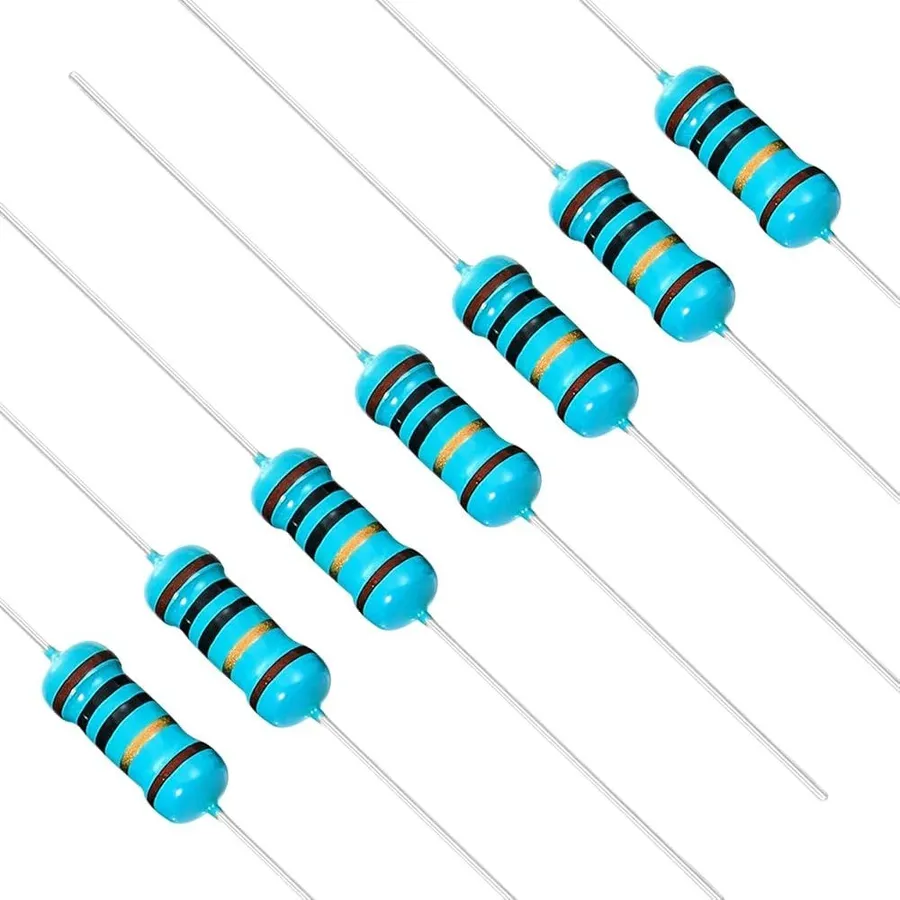
Through-hole resistors are fundamental electronic components characterized by their axial leads, which are inserted through holes in a printed circuit board (PCB) and soldered on the opposite side, serving to limit or regulate the flow of electrical current. Their structure typically comprises a resistive element encased in a protective material, with leads extending for easy connection to circuit boards.
The core principle of a through-hole resistor is based on Ohm's Law, where the resistor's material and physical properties (length and cross-sectional area) determine its opposition to current flow. The resistive element can be constructed from various materials, including carbon composition, carbon film, metal film, or wire, each offering unique performance characteristics in terms of precision, temperature stability, and power handling capability. This leads to various use cases and applications for this essential component.
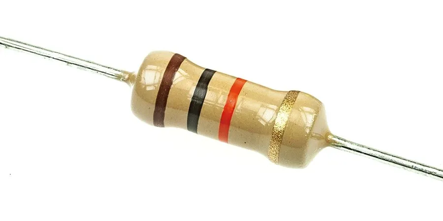
Through-hole resistors, fundamental components in electronic circuits, are categorized based on their construction materials and manufacturing processes, which significantly influence their electrical characteristics, accuracy, temperature coefficient, and suitability for different applications. The primary types include carbon film, metal film, and wire-wound resistors.
| Resistor Type | Construction | Typical Tolerance | Temperature Coefficient (ppm/°C) | Power Rating | Advantages | Disadvantages | Typical Applications |
|---|---|---|---|---|---|---|---|
| Carbon Film | Thin carbon film deposited on a ceramic substrate | ±2% to ±5% | ±250 to ±1500 | 0.125W to 2W | Low cost, widely available, general purpose | Less stable, lower precision, susceptible to noise and temperature effects | General purpose circuits, low cost consumer electronics |
| Metal Film | Thin metal alloy film deposited on a ceramic substrate | ±0.1% to ±1% | ±25 to ±100 | 0.05W to 1W | High precision, low noise, good temperature stability | More expensive than carbon film resistors | Precision circuits, audio applications, measurement devices |
| Wire-Wound | Metallic wire wound around an insulating core | ±0.01% to ±5% | ±20 to ±400 | 1W to 50W+ | High power rating, high stability, low noise | Large physical size, lower frequency response, can act as an inductor | High power circuits, current sensing, braking resistors |
The temperature coefficient, a crucial parameter, indicates how much the resistance changes with temperature. Metal film resistors generally exhibit the lowest temperature coefficient, ensuring more stable operation over a wider range of temperatures. The accuracy of a resistor is determined by its manufacturing tolerances. Metal film resistors are the most accurate, followed by carbon film and then wire-wound resistors.
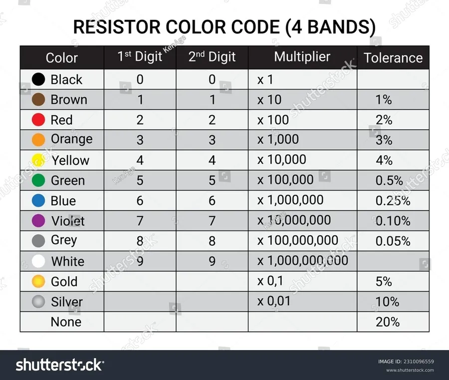
The color code system on through-hole resistors is a standardized method for indicating their resistance value and tolerance. This system uses colored bands printed on the resistor body, each color representing a numerical value or a multiplier. Understanding this color code is crucial for selecting and using resistors correctly in electronic circuits.
| Color | Digit | Multiplier | Tolerance |
|---|---|---|---|
| Black | 0 | 1 | ±20% |
| Brown | 1 | 10 | ±1% |
| Red | 2 | 100 | ±2% |
| Orange | 3 | 1,000 | |
| Yellow | 4 | 10,000 | |
| Green | 5 | 100,000 | ±0.5% |
| Blue | 6 | 1,000,000 | ±0.25% |
| Violet | 7 | 10,000,000 | ±0.1% |
| Gray | 8 | ±0.05% | |
| White | 9 | ||
| Gold | 0.1 | ±5% | |
| Silver | 0.01 | ±10% | |
| None | ±20% |
The most common through-hole resistors have four or five color bands. For a four-band resistor, the first two bands represent the first two digits of the resistance value, the third band is the multiplier, and the fourth band indicates the tolerance. For a five-band resistor, the first three bands represent the first three digits of the resistance value, the fourth band is the multiplier, and the fifth band indicates the tolerance.
For example, consider a four-band resistor with color bands of (Brown, Black, Red, Gold). Based on the color code table, this resistor has the following specifications: Brown=1, Black=0, Red=100, Gold=±5%. Therefore, the resistance value is calculated as follows: (10 x 100) = 1000 ohms, or 1 kΩ, with a tolerance of ±5%.
In a five-band resistor with color bands of (Red, Red, Black, Black, Brown), the first three bands are read as Red=2, Red=2, and Black=0, so the first three digits are 220. The fourth band, black, is the multiplier, 1, and the fifth band, brown, denotes a ±1% tolerance. Thus, the resistance value is 220 Ω with ±1% tolerance. Five-band resistors are commonly used in more precise applications.
Special markings may exist for specific types of resistors or to indicate additional parameters, for example, a temperature coefficient. These markings are less common in typical through-hole resistors, but should be noted if you have some special resistors.
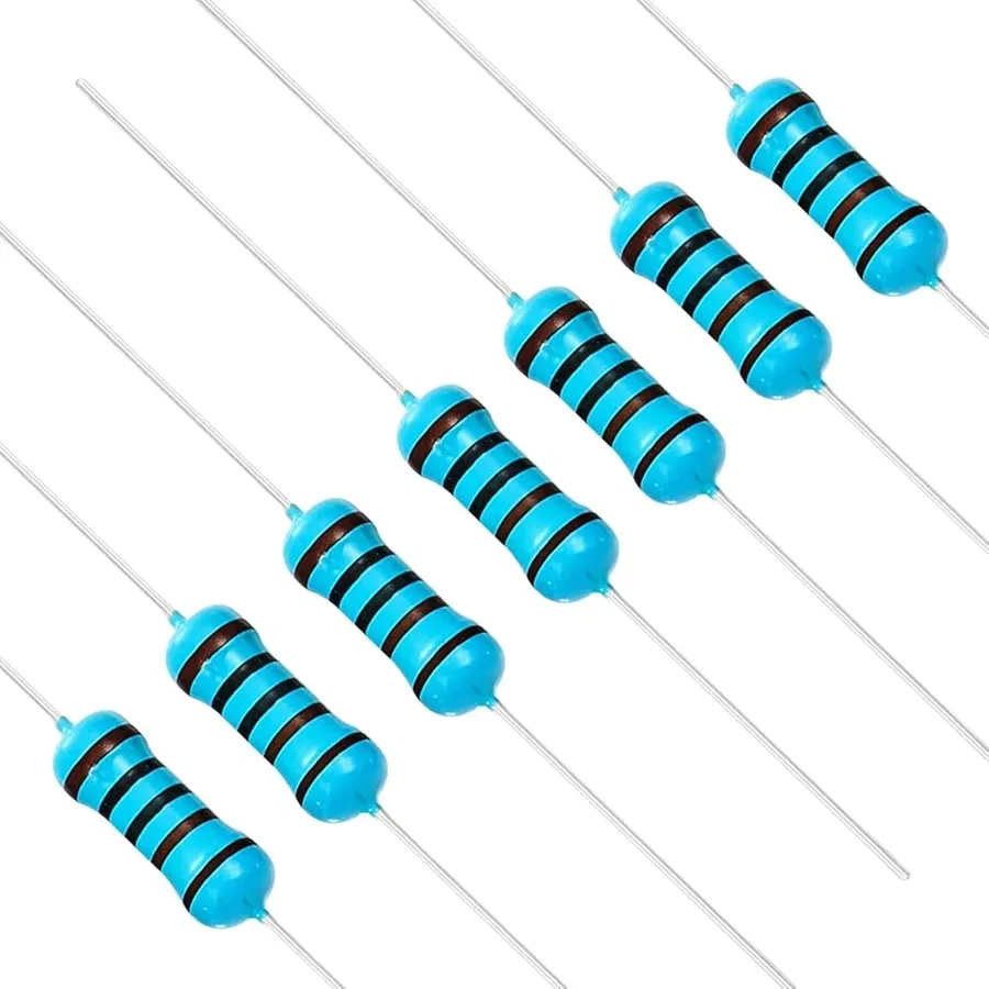
Through-hole resistors are manufactured in a variety of physical sizes, each corresponding to a specific power rating and, consequently, a physical footprint. Understanding these sizes and their associated footprints is crucial for proper PCB design and component selection. These parameters directly influence the resistor's heat dissipation capabilities and the space it occupies on a circuit board.
Standard through-hole resistor sizes are typically defined by their power rating, commonly expressed in watts (W). The physical dimensions of the resistor body and lead spacing are directly related to this power rating. Common power ratings include 1/8W, 1/4W, 1/2W, 1W, and 2W, each with corresponding physical dimensions. As the power rating increases, so does the physical size of the resistor, allowing it to dissipate more heat.
| Power Rating (W) | Typical Body Diameter (mm) | Typical Body Length (mm) | Typical Lead Spacing (mm) |
|---|---|---|---|
| 1/8 | 2.3 | 6.5 | 5.08 |
| 1/4 | 2.5 | 7.0 | 7.62 |
| 1/2 | 3.5 | 9.0 | 10.16 |
| 1 | 5.0 | 11.5 | 10.16 |
| 2 | 6.5 | 15.0 | 10.16 |
It's imperative to note that these dimensions can vary slightly between manufacturers; therefore, always consult the specific datasheet for the exact physical parameters. The datasheet provides detailed information regarding the resistor's dimensions, including body diameter, body length, and lead spacing. For precise PCB design, these specifications are critical to ensure proper component fit and placement.
Regarding mounting techniques, through-hole resistors can be mounted both horizontally and vertically. Horizontal mounting is the most common approach, where the resistor lies flat on the PCB. Vertical mounting is used in situations where PCB space is limited, with one lead bent in a 'U' shape, allowing the resistor to stand upright on the board. Specific mounting techniques may vary on datasheets. PCB footprints for through-hole resistors typically consist of two pads (one for each lead) that are spaced according to the resistor's lead pitch, which is the distance between the centers of the leads. Standard footprints are available in CAD software, and their corresponding datasheets provide exact dimensions.

Through-hole and surface mount resistors represent the two primary methods of component mounting in electronic circuits. Through-hole resistors, with their leads extending through holes in the printed circuit board (PCB), offer robust mechanical connections. In contrast, surface mount resistors (SMD) are soldered directly onto the PCB surface, enabling smaller device footprints and higher density designs.
| Feature | Through-Hole Resistors | Surface Mount Resistors |
|---|---|---|
| Mounting | Leads inserted through PCB holes | Soldered directly to PCB surface |
| Size | Larger; requires more PCB space | Smaller; allows for higher component density |
| Assembly | Suitable for manual assembly and prototyping | Primarily used with automated assembly equipment (pick-and-place) |
| Mechanical Strength | Robust, strong physical connection | Less mechanically resilient, more susceptible to stress |
| Cost | Generally higher component cost and assembly costs for high volume | Lower component cost for high-volume automated assembly |
| Thermal Performance | Better heat dissipation due to lead through PCB | Heat dissipation more dependent on PCB design |
| Applications | Prototyping, manual assembly, high power applications | High-density designs, mass production, compact devices |
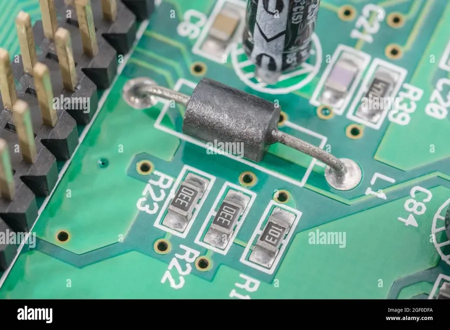
Through-hole resistors are fundamental components in electronics, serving diverse functions across a wide spectrum of applications. Their robust structure and ease of prototyping make them indispensable in various fields, from educational kits to sophisticated industrial equipment. The adaptability of through-hole resistors allows for creative design implementations and ensures electrical current control in countless systems.
Selecting the appropriate through-hole resistor is crucial for optimal circuit performance and reliability. This process involves a careful consideration of several key parameters to ensure the component meets the specific requirements of the application. The correct choice will prevent circuit failure, maintain the desired performance characteristics, and ensure longevity.
Here is a checklist to guide you through the selection process:
This section addresses common inquiries regarding through-hole resistors, providing practical information on their usage, storage, and handling to ensure optimal performance and longevity. We aim to provide clear and concise answers to help you navigate the world of through-hole resistors.
The field of resistor technology continues to evolve, driven by demands for increased performance, miniaturization, and integration with advanced electronic systems. This section explores some of the cutting-edge developments and future directions in through-hole resistor technology.
Through-hole resistors are a fundamental component in the world of electronics, essential for both simple and complex circuits. Understanding their various types, color codes, and applications empowers users to choose and utilize them effectively in diverse projects, from a basic through hole resistor circuit to specialized applications. By gaining a solid grasp of these components, we contribute to creating more reliable and efficient electronic devices today and in the future.

