From the smartphones in our pockets to the sophisticated machinery in factories, SMD electronics are the unseen workhorses of our modern world. These tiny surface-mounted devices, or SMDs, have revolutionized electronic design and manufacturing. This guide will demystify SMD electronics, exploring their technology, advantages, and applications while contrasting them with traditional through-hole methods. Join us as we uncover how these miniature marvels are reshaping our technological landscape.
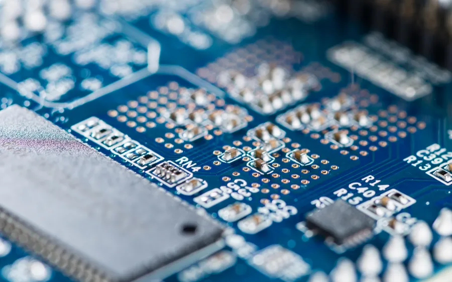
Surface Mount Technology (SMT) is the process of assembling electronic circuits by directly mounting electronic components onto the surface of a printed circuit board (PCB). This manufacturing methodology contrasts sharply with traditional through-hole technology, where component leads are inserted through holes in the PCB and soldered on the opposite side.
SMT's advent has been instrumental in the miniaturization of electronics, allowing for significantly denser circuit board designs and enabling the production of smaller, lighter, and more powerful electronic devices. This technology is foundational in modern electronics manufacturing due to its capability for high-volume automated assembly and improved circuit performance.
| Feature | Surface Mount Technology (SMT) | Through-Hole Technology |
|---|---|---|
| Component Mounting | Components are mounted directly onto the surface of the PCB. | Component leads are inserted through holes in the PCB and soldered on the other side. |
| Component Size | Typically smaller, allowing for high-density circuits. | Components are generally larger and require more space. |
| Lead Type | Components have short leads or pads for surface soldering. | Components have longer leads for insertion through holes. |
| Assembly Process | Automated assembly processes are common; uses solder paste and reflow soldering. | Manual insertion and wave soldering methods are typically used. |
| Circuit Density | Supports high-density circuit design and miniaturization. | Lower component density limitations. |
| PCB Design | Requires specific pad layouts and precise alignment for component placement. | Requires through-holes for component lead insertion. |
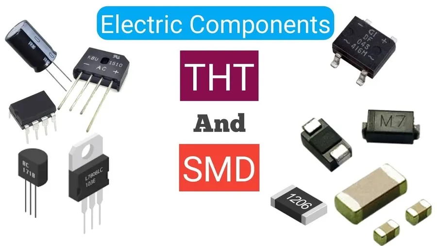
Surface Mount Devices (SMDs) are the electronic components designed for direct mounting onto the surface of a Printed Circuit Board (PCB). Unlike through-hole components, SMDs lack leads that pass through holes in the board. This fundamental design difference is the key factor enabling the miniaturization and increased density of modern electronic circuits. SMDs are not the process itself, but the building blocks of Surface Mount Technology (SMT).
The terms SMD (Surface Mount Device) and SMT (Surface Mount Technology) are often used interchangeably, leading to confusion. However, they represent distinct concepts within electronics manufacturing. SMD refers to the actual electronic components, while SMT is the manufacturing process that uses these components. Understanding this distinction is crucial for anyone working with modern electronic assemblies.
| Feature | SMD (Surface Mount Device) | SMT (Surface Mount Technology) |
|---|---|---|
| Definition | Refers to the electronic component itself. | Refers to the manufacturing process. |
| Type | Physical components (e.g., resistors, capacitors, ICs). | Assembly process. |
| Purpose | Designed for surface mounting onto PCBs. | Method for assembling SMD components onto PCBs. |
| Example | An SMD resistor is a physical component. | SMT involves solder paste application and reflow soldering. |
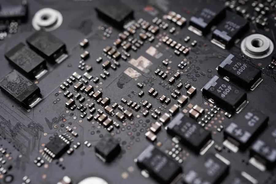
The adoption of Surface Mount Device (SMD) electronics in modern manufacturing is driven by their distinct advantages over traditional through-hole technology. These benefits span multiple aspects of electronics design and production, contributing to the ubiquitous nature of SMD components in contemporary devices.
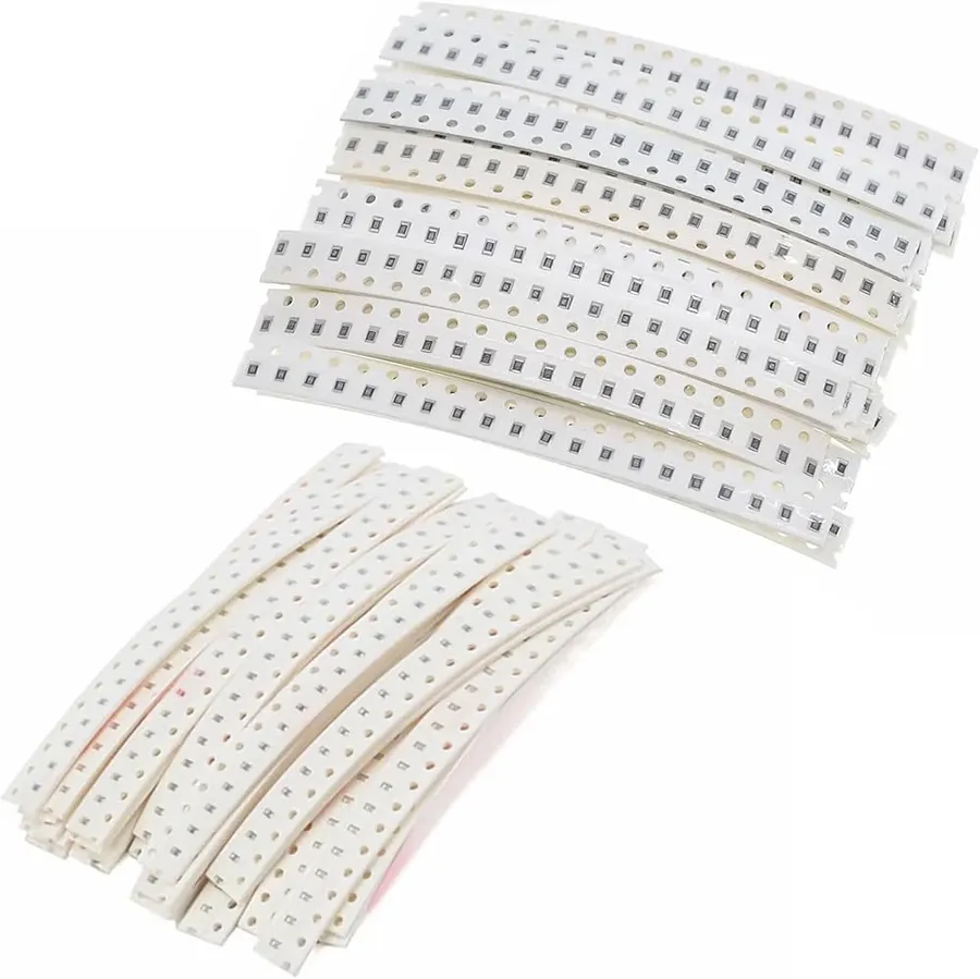
Surface Mount Devices (SMDs) are fundamental to modern electronics, enabling miniaturization and high-density circuit designs. These components, unlike their through-hole counterparts, lack leads and are designed to be soldered directly onto the surface of a printed circuit board (PCB). This section will detail the most common types of SMD components and their role in electronics.
| Component Type | Description | Typical Application |
|---|---|---|
| SMD Resistors | Passive components that limit current flow. Available in various resistance values and power ratings. | Current limiting, voltage division |
| SMD Capacitors | Passive components that store electrical energy. Available in different dielectric materials. | Energy storage, filtering, decoupling |
| SMD Inductors | Passive components that store energy in a magnetic field, often used in circuits to resist changes in current. | Filtering, impedance matching, energy storage |
| SMD Diodes | Semiconductor devices that allow current to flow primarily in one direction. | Rectification, signal processing, protection |
| SMD Transistors | Semiconductor devices used to amplify or switch electronic signals and electrical power. | Amplification, switching |
The proliferation of SMD components has led to a need for standardized sizes and specifications, such as those defined by organizations like the IEC. Standards address factors like physical dimensions (length, width, height), pin spacing and material composition. Common package sizes for these components are often designated by numeric codes, such as 0603, 0805, and 1206, where the numbers refer to the size of the component in imperial or metric units. These standards facilitate mass manufacturing processes by allowing automatic placement machines to accurately handle and position them on PCBs.
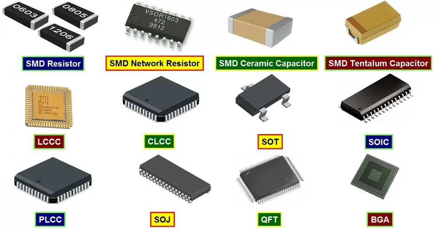
Surface Mount Devices (SMD) are available in a multitude of package types and sizes, each designed to meet specific application requirements regarding miniaturization, performance, and assembly constraints. The selection of a suitable package is a critical aspect of PCB design, affecting both the final size of the product and its manufacturability. Understanding these package types and sizes is crucial for engineers and designers working with surface mount technology.
| Package Type | Description | Typical Applications | Key Considerations |
|---|---|---|---|
| 0603 | Small rectangular package with dimensions of approximately 0.6mm x 0.3mm. One of the smallest standard SMD packages. | Consumer electronics, mobile devices, miniaturized sensors. | Requires precise pick-and-place equipment, challenging for hand soldering. |
| 0805 | Rectangular package with dimensions of approximately 0.8mm x 0.5mm. Slightly larger than 0603 for better handling. | General-purpose circuits, wearable technology, low-power applications. | Improved solderability over 0603, still requires care in handling. |
| 1206 | Rectangular package with dimensions of approximately 1.2mm x 0.6mm. Offers a good balance between size and ease of use. | Industrial controls, automotive electronics, power supplies. | Easier to handle than smaller sizes, better heat dissipation. |
| SOIC (Small Outline Integrated Circuit) | Gull-wing leads on two sides, various widths and pin counts available. | Operational amplifiers, logic gates, driver circuits. | Good for ICs with a medium number of pins, requires attention to pin pitch during soldering. |
| QFN (Quad Flat No-Leads) | Pads on the underside of the package, no external leads, good thermal performance. | Microcontrollers, wireless communication modules, high-performance applications. | Requires reflow soldering, difficult to inspect solder joints. |
| BGA (Ball Grid Array) | Array of solder balls on the underside, high pin count, good thermal performance. | Processors, FPGAs, memory devices. | Requires specialized BGA rework equipment, challenging for visual inspection. |
The naming convention for some packages like 0603, 0805, and 1206 refers to their dimensions in hundredths of an inch. For example, an 0603 package is 0.06 inches long and 0.03 inches wide, while an 0805 is 0.08 inches long and 0.05 inches wide. Understanding these size codes is key when selecting the components as well as when designing the PCB layout. The dimensions are critical for the pick and place machines, stencil design, and overall solderability.
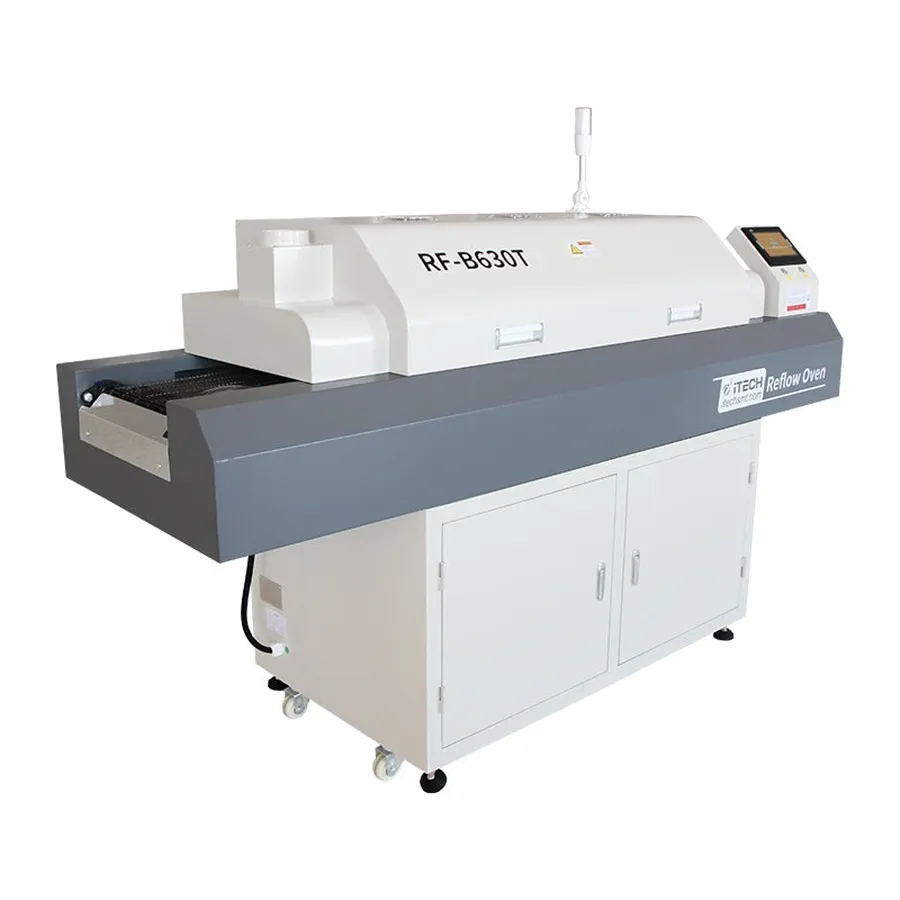
The Surface Mount Technology (SMT) assembly process is a highly automated and precise method for attaching Surface Mount Devices (SMDs) to a Printed Circuit Board (PCB). This process, crucial for modern electronics manufacturing, involves several key stages that ensure efficient and reliable production.
Compared to traditional through-hole assembly, SMT offers significant advantages in terms of speed, precision, and efficiency, particularly for mass production. The process requires specialized equipment, such as stencil printers, pick-and-place machines, and reflow ovens. Furthermore, due to the small size of components and the required precision, SMT assembly demands skilled technicians and engineers for optimal operation and maintenance. The SMT assembly process is not only efficient but also enables the miniaturization of electronic devices due to the very small nature of SMD components, and ultimately reduces production cost.
This section addresses common questions regarding Surface Mount Devices (SMDs) and Surface Mount Technology (SMT). Understanding these concepts is crucial for anyone working with modern electronics.
For hobbyists, venturing into SMD electronics opens a realm of compact and efficient circuit designs, albeit with a learning curve. Successfully working with surface mount devices requires specific tools, techniques, and a good understanding of the challenges involved.
SMD electronics have undeniably transformed the world of electronic design and manufacturing. Their smaller sizes, increased efficiency, and reduced manufacturing costs have made them an essential component of nearly all modern electronic devices. As technology continues to advance, the reliance on and innovation within the SMD domain are only expected to increase, solidifying their crucial role in our increasingly digitized future. From large manufacturing operations to hobbyists, SMD electronics are the present and future of our devices.

