In today's miniaturized world of electronics, the Surface Mount Device (SMD) transistor is a workhorse, powering countless devices from smartphones to sophisticated industrial equipment. These tiny components, often no larger than a grain of rice, pose unique challenges and opportunities for engineers and hobbyists alike. This article provides a comprehensive guide, breaking down the complexities of identifying, selecting, and effectively using SMD transistors in various applications, moving from theory to practice.
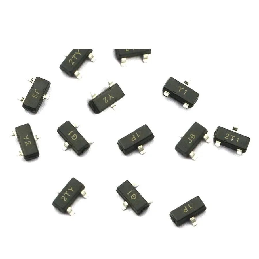
Surface Mount Device (SMD) transistors are semiconductor devices designed for direct mounting onto a printed circuit board (PCB) surface, contrasting with traditional through-hole components. This miniaturization offers significant advantages in modern electronics, enabling compact and densely populated circuit designs.
SMD transistors, encompassing Bipolar Junction Transistors (BJTs) and Metal-Oxide-Semiconductor Field-Effect Transistors (MOSFETs), facilitate a broad range of applications from amplification and switching to signal processing. Their prevalence stems from their efficiency in automated manufacturing processes, reduced size, and improved performance characteristics.
| Transistor Type | Description | Typical Applications |
|---|---|---|
| Bipolar Junction Transistor (BJT) | Current-controlled device, available in NPN and PNP configurations. | Amplification, switching, and signal processing in low to medium power applications. |
| Metal-Oxide-Semiconductor Field-Effect Transistor (MOSFET) | Voltage-controlled device, available in N-channel and P-channel configurations. | High-efficiency switching, power management, and low-signal amplification. |
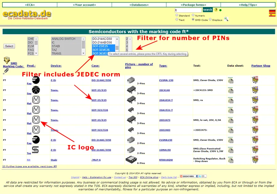
Surface Mount Device (SMD) transistors, due to their diminutive size, utilize alphanumeric codes rather than full part numbers for identification. These codes are essential for selecting the correct replacement or understanding the component's specifications. This section provides a practical guide to deciphering these markings, ensuring accurate identification and proper application.
SMD transistor markings are often a combination of letters and numbers, which can sometimes be manufacturer-specific. While there isn't a universal standard, certain patterns and databases can aid in identification. These markings typically encode the transistor's type (NPN, PNP, MOSFET), manufacturer, and sometimes specific performance characteristics.
Key challenges arise from the lack of standardization, leading to variations in marking styles across manufacturers. Additionally, the incredibly small size of these components often limits the amount of information that can be physically printed on the package. It is not uncommon to find codes that require referencing online databases or manufacturer datasheets for accurate interpretation.
| Marking Example | Transistor Type | Description |
|---|---|---|
| 1A | NPN BJT | Common code for a specific NPN bipolar junction transistor. |
| 2A | PNP BJT | Common code for a specific PNP bipolar junction transistor. |
| 1AW | NPN BJT | NPN transistor likely from a specific manufacturer. |
| A7s | MOSFET | MOSFET transistor with specific characteristics |
| W1P | NPN BJT | Specific NPN Transistor, code might be specific to a particular manufacturer. |
Accurate identification often requires utilizing online databases which catalog SMD codes with their corresponding part numbers and datasheet information. Some resources include: SMD Codebooks, component databases from distributors (e.g., DigiKey, Mouser), and manufacturer datasheets. The following table shows a few such resources, their features, and their limitations.
| Resource | Description | Strengths | Limitations |
|---|---|---|---|
| SMD Codebooks | Printed or online databases that list SMD codes with their corresponding components. | Can be a comprehensive, easy-to-use resource. | May not have the most current or manufacturer-specific data. |
| Distributor Websites (e.g., DigiKey, Mouser) | Online databases associated with electronics component suppliers. | Includes a large number of component listings with the latest pricing, and up-to-date component information. | Might be overly complex and difficult to navigate for simple SMD code lookups. |
| Manufacturer Datasheets | Specific documentation from the component's manufacturer. | Most reliable and detailed source of component information. | Can be complex, and requires first identification of the manufacturer. |
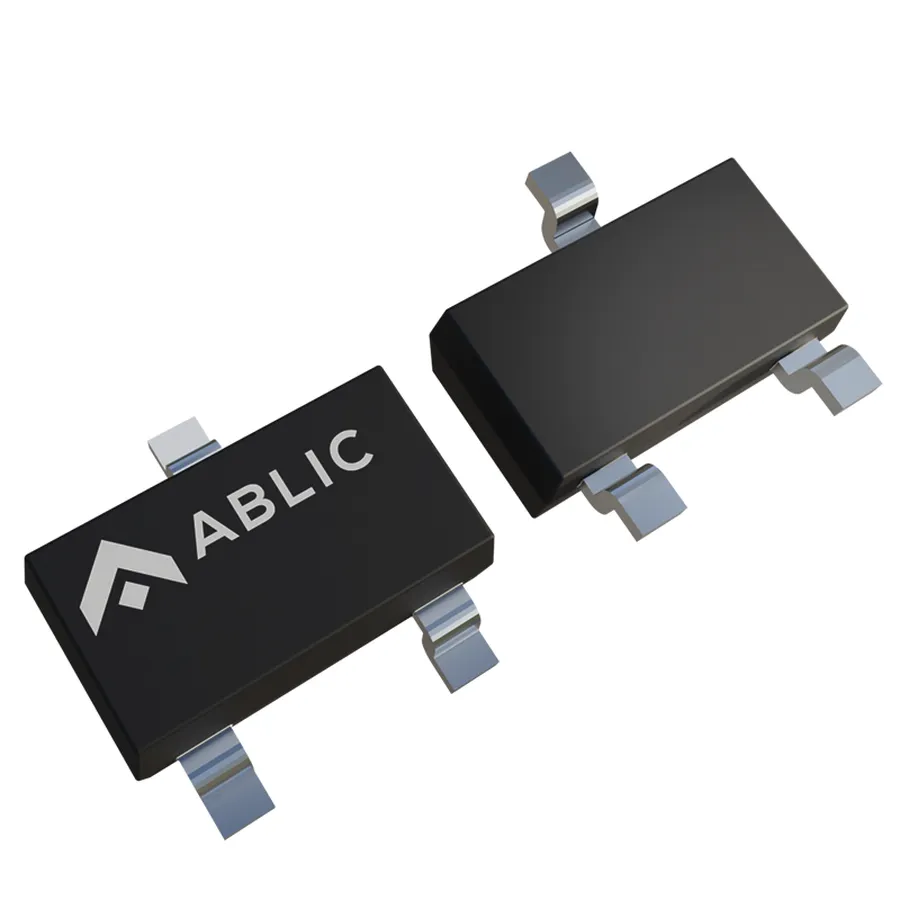
Surface Mount Device (SMD) transistors are housed in various standardized packages, each designed for specific applications and offering different thermal and electrical characteristics. Understanding these packages is crucial for proper component selection, circuit design, and PCB layout. This section details common SMD transistor package types, their dimensions, and typical applications.
| Package Type | Dimensions (mm) | Number of Pins | Typical Applications | Thermal Characteristics |
|---|---|---|---|---|
| SOT-23 | 2.9 x 1.3 x 1.0 | 3 | General-purpose switching, low-power amplification, small signal processing | Moderate heat dissipation |
| SOT-223 | 6.5 x 3.5 x 1.6 | 4 | Medium power switching, linear regulation, moderate current applications | Good heat dissipation due to larger pad area |
| SOT-323 | 2.0 x 1.25 x 0.95 | 3 | Miniature applications, low-power switching, space-constrained designs | Low heat dissipation due to small size |
| SOT-89 | 4.5 x 2.5 x 1.5 | 3 | Medium power amplification, switching, moderate current applications | Moderate heat dissipation |
| SC-70 (SOT-343) | 2.0 x 1.25 x 0.9 | 3 | Miniature low-power applications, space-constrained designs | Low heat dissipation |
| TO-252 (DPAK) | 6.6 x 6.0 x 2.3 | 3 | Medium to high power applications, power switching, voltage regulation | Good heat dissipation with heat sink connection |
| TO-263 (D2PAK) | 10.2 x 9.0 x 4.5 | 3 | High power applications, motor control, high current switching | Excellent heat dissipation with heat sink connection |
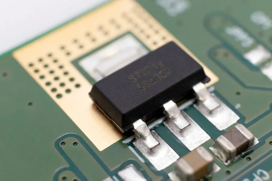
Identifying Surface Mount Device (SMD) transistors with unclear or missing markings presents a challenge, but a systematic approach using component testers, datasheets, and visual inspection can overcome this. This section outlines practical methods to accurately identify such components.
It's critical to note that even similar looking SMD components can have very different electrical characteristics; accurate identification is essential to ensure circuit functionality and avoid damage.
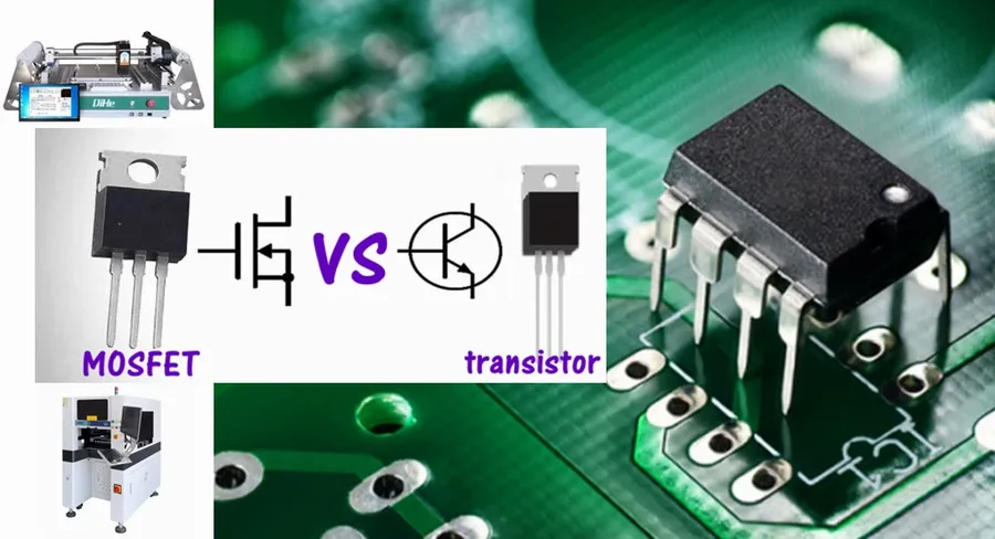
Finding equivalent SMD transistors is crucial when the original component is unavailable or needs replacement. This process involves identifying a suitable alternative that meets or exceeds the specifications of the original part. This requires a systematic approach using datasheets, online databases, and a thorough understanding of transistor parameters.
When searching for a replacement, it is vital to consider key electrical characteristics to ensure the circuit's proper function. These include parameters such as transistor type (NPN, PNP, N-channel MOSFET, P-channel MOSFET), voltage ratings (Vce, Vds), current ratings (Ic, Id), power dissipation, and gain (hFE for BJT, transconductance for FET). The replacement transistor should have specifications that are equal to or greater than those of the original.
| Parameter | Description | Importance for Replacement |
|---|---|---|
| Transistor Type | NPN, PNP, N-channel MOSFET, P-channel MOSFET | Must match the original. Cannot interchange NPN with PNP or MOSFET with BJT. |
| Voltage Ratings (Vce, Vds) | Maximum voltage the transistor can handle | Replacement must have equal or higher voltage rating to prevent failure. |
| Current Ratings (Ic, Id) | Maximum current the transistor can handle | Replacement must have equal or higher current rating to prevent overheating and failure. |
| Power Dissipation | Maximum power the transistor can safely dissipate | Replacement must have equal or higher power rating to prevent overheating and failure. |
| Gain (hFE) | Current gain of BJT | Should be similar for BJT applications. Matching gain can be crucial in certain circuits. |
| Transconductance (gm) | The ratio of output current to input voltage | Should be similar for FET applications. Matching transconductance can be crucial in certain circuits. |
Several online tools and databases are invaluable in the search for equivalent SMD transistors. These include:
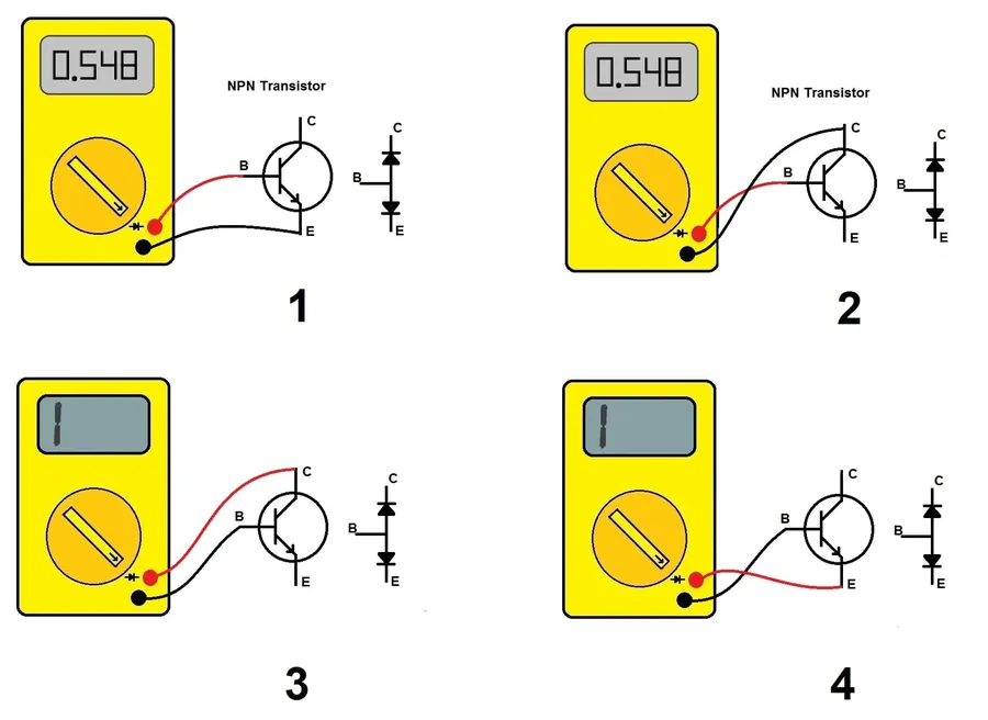
Verifying the functionality of SMD transistors is crucial for circuit diagnosis and repair. This section provides a practical guide on using multimeters and component testers to assess SMD transistor performance and troubleshoot common issues.
Testing SMD transistors requires careful handling due to their small size. Two main tools are used: multimeters for basic tests and dedicated component testers for more detailed analysis.
| Test Type | Tool | Procedure | Expected Results |
|---|---|---|---|
| Diode Test (BJT) | Multimeter | Measure voltage drop between base-emitter and base-collector | ~0.7V forward bias, OL/high resistance in reverse bias |
| On/Off Test (MOSFET) | Multimeter | Measure resistance between drain and source with gate high and low | Low resistance when gate is activated, high resistance otherwise |
| Transistor Gain (hFE) | Component Tester | Connect transistor to the tester; initiate measurement. | Value should match datasheet spec or a known working component. NPN should read a positive number, and PNP a negative |
| Pin Identification | Component Tester | Connect transistor to the tester, identify by model number or by automatic pin identification | Identifies the transistor’s base, collector, and emitter or gate, drain and source pins. |
When troubleshooting, consider these common problems:
When a fault is detected, it is essential to carefully inspect the soldering connections, the transistor package for physical damage, and review the circuit diagram to ensure correct placement and orientation. Confirm readings with data sheet specifications and if a component is suspect, replace it with a known good component to isolate the issue.
This section addresses common inquiries regarding Surface Mount Device (SMD) transistors, providing concise and practical answers to enhance understanding and application.
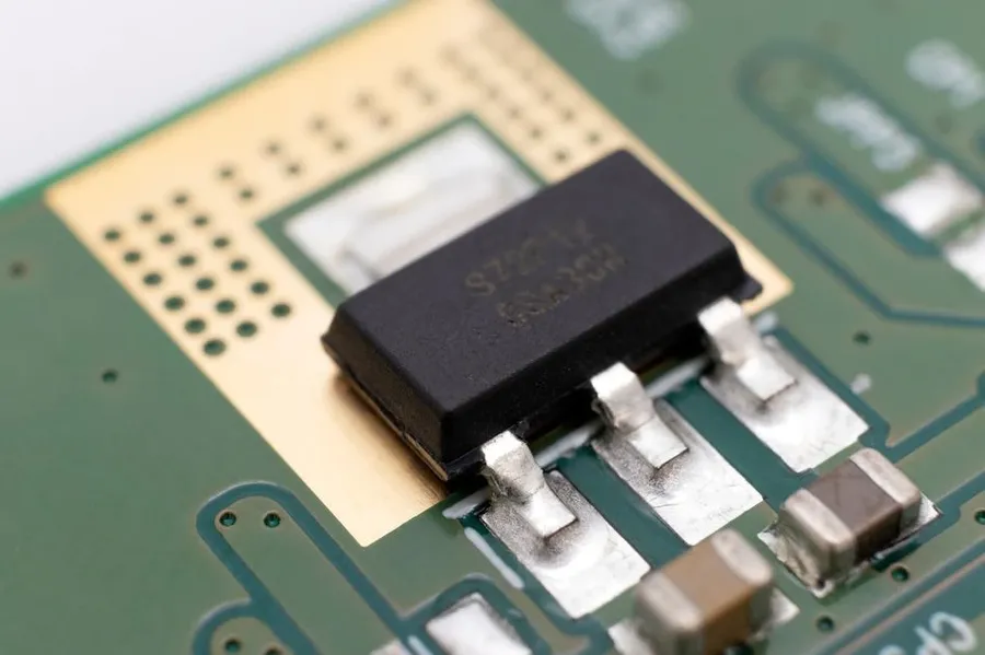
Selecting the correct SMD transistor for a specific application is crucial for optimal circuit performance and reliability. This process involves carefully considering several key parameters, including voltage, current, power, frequency requirements, and the specific operational needs of the circuit. This section will guide you through the process, providing design best practices to aid in the selection.
| Parameter | Description | Importance in Selection |
|---|---|---|
| Voltage (VCE or VDS) | Maximum collector-emitter voltage for BJTs or drain-source voltage for MOSFETs. | Must exceed the maximum voltage expected in the application to prevent breakdown. |
| Current (IC or ID) | Maximum collector current for BJTs or drain current for MOSFETs. | Should be rated higher than the maximum current expected in the application to prevent failure due to overheating. |
| Power Dissipation (PD) | Maximum power the transistor can dissipate as heat. | Must be adequate for the expected power consumption; heat sinks may be necessary in high-power applications. |
| Gain (hFE or gm) | Current gain of BJTs or transconductance of MOSFETs. | Affects the amplification capabilities and should match the circuit requirements. |
| Switching Speed | How quickly a transistor can switch between ON and OFF states. | Crucial for high-frequency applications; slower switching speed may lead to inefficiencies. |
| Operating Temperature | The range of temperature that the transistor can operate within. | The transistor should be able to operate in the temperature range of the environment. |
| Package Type | Physical casing of the transistor (e.g., SOT-23, SOT-223) | Affects the ease of mounting and heat dissipation; must match PCB layout. |
Additionally, when selecting an SMD transistor, It's crucial to consider design best practices to ensure reliability and performance. Factors include thermal management, appropriate PCB layout, and signal integrity. For thermal management, consider using heat sinks or larger PCB copper areas connected to the transistor to dissipate heat.
For PCB layout, place the transistor in an area that allows for efficient heat dissipation and minimize long traces to prevent signal degradation and impedance mismatches. If high-frequency signals are involved, use impedance matching techniques, and separate analog and digital signals to reduce noise. Finally, make sure the operating conditions of the circuit does not cause the maximum rating of the device to be exceeded.
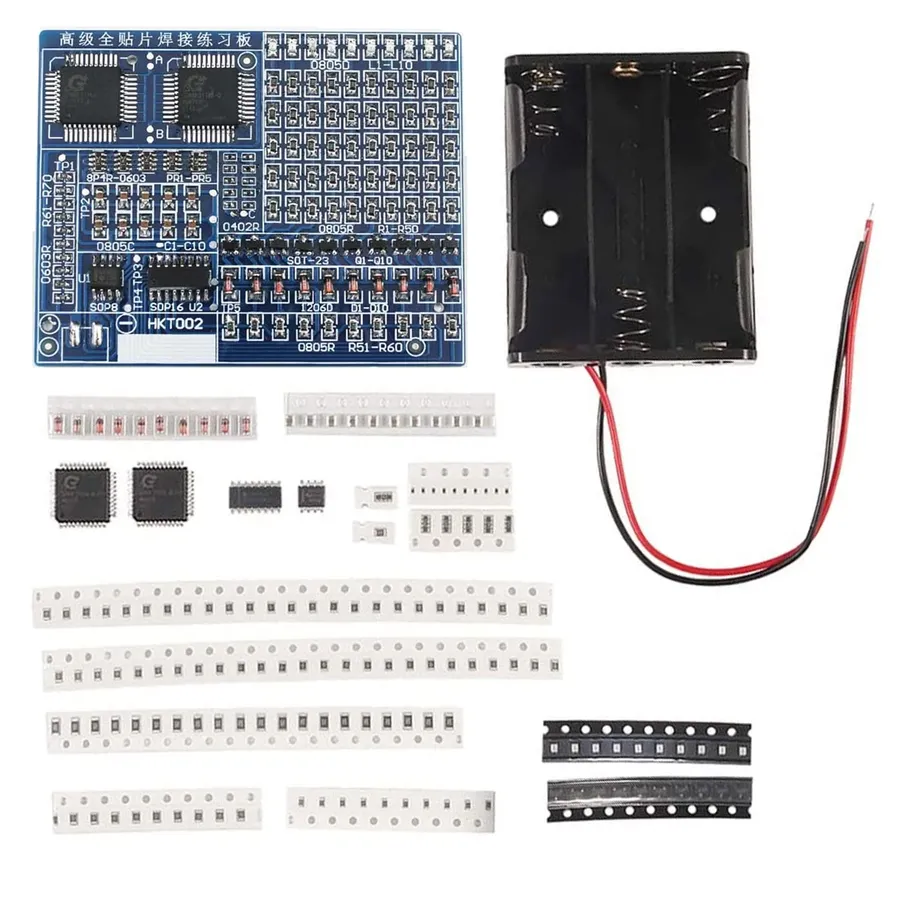
Soldering and handling Surface Mount Device (SMD) transistors require precision and care to avoid damage, ensuring reliable connections. The small size and delicate nature of these components necessitate the use of proper techniques and equipment.
SMD transistors, despite their diminutive size, are vital components in modern electronics. Mastering their identification, selection, and use is crucial for any electronic design enthusiast or professional. By following the guidelines and tips covered in this article, you'll be well-equipped to tackle any project involving these surface mount components, ensuring reliable and efficient functionality. The world of SMD transistors can be a challenge, but with the right knowledge, they open up many new possibilities for design and innovation.

