Have you ever wondered why adding more pathways in a circuit actually reduces the overall resistance? It's counterintuitive, yet adding parallel resistors is a fundamental technique in electrical engineering. This article delves into the fascinating world of parallel resistors, explaining how they work, why they're useful, and how you can calculate their combined effect. We'll explore real-world applications, dispel common misconceptions, and provide you with the practical knowledge to master this essential concept.
At the heart of electrical circuit analysis lies the fundamental concept of resistance, which opposes the flow of electrical current. This opposition, measured in ohms (Ω), is intrinsic to every material. Ohm's Law, expressed as V = IR, elegantly defines the relationship between voltage (V), current (I), and resistance (R). Voltage, measured in volts, is the electrical potential difference driving current, while current, measured in amperes, is the rate at which charge flows through a circuit. Understanding these interdependencies is crucial to grasp the behavior of electrical circuits, and provides the basis for analyzing parallel resistor arrangements and their impact on overall circuit resistance and current distribution.
| Parameter | Symbol | Unit | Description |
|---|---|---|---|
| Resistance | R | Ohms (Ω) | Opposition to current flow |
| Voltage | V | Volts (V) | Electrical potential difference |
| Current | I | Amperes (A) | Rate of charge flow |

Parallel resistors are a fundamental circuit configuration where two or more resistors are connected side-by-side, with each resistor having both of its terminals connected to the same two nodes within the circuit. This arrangement provides multiple pathways for current to flow, in contrast to a series circuit where the current has only one path. The key characteristic of parallel resistors is that they all experience the same voltage drop across their terminals, irrespective of their individual resistance values.
The implications of this connection are significant in circuit behavior, directly influencing how current is distributed and how the overall resistance of the circuit is affected. Specifically, the addition of parallel resistors results in a reduction of the total equivalent resistance, a principle we will delve into further in subsequent sections. Understanding parallel connections is crucial for various electronic applications, ranging from basic circuits to complex systems. In essence, if multiple resistors share a common beginning and a common end point, then they are by definition, in parallel.
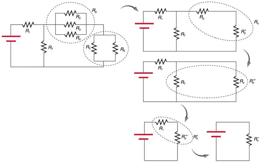
Adding resistors in parallel decreases the overall resistance of a circuit because it provides additional pathways for current to flow. This principle can be intuitively understood by considering the flow of water in a river. When a river splits into multiple channels, the water encounters less resistance and flows more easily. Similarly, adding parallel resistors provides more routes for electrical current, effectively reducing the total impedance to current flow, resulting in lower total resistance.
Think of resistance as the measure of how much a material opposes the flow of electric current. In a series circuit, all current has to flow through each resistor sequentially, so the resistances add up. However, in a parallel circuit, the current divides, with some flowing through each resistor. This division of current effectively lowers the overall resistance the current encounters.
Mathematically, the reciprocal of the total resistance in a parallel circuit equals the sum of the reciprocals of individual resistances. This relationship demonstrates that adding a resistor in parallel always decreases the total equivalent resistance. No matter how small the added resistor is, it will always reduce the combined value.
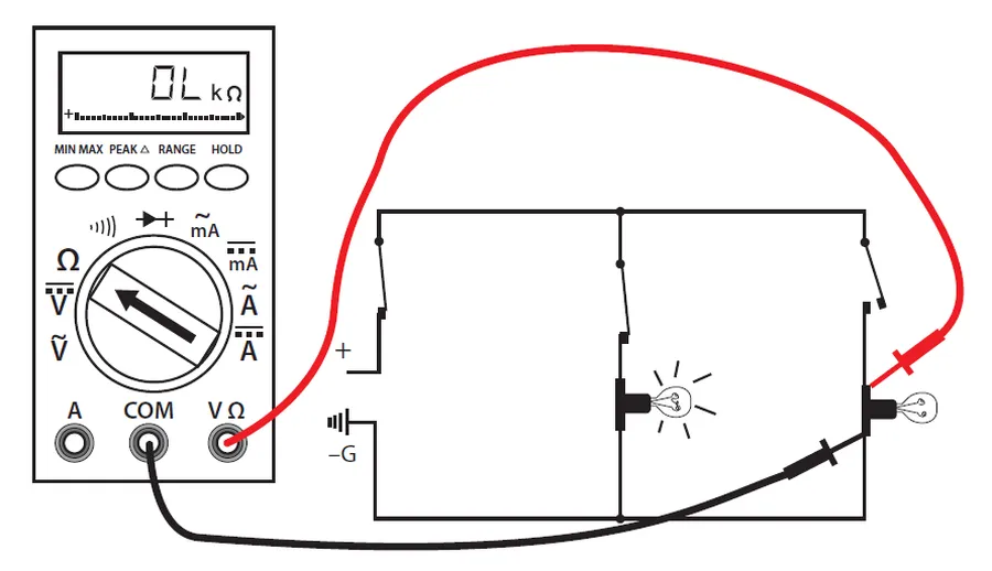
Calculating the total resistance of parallel resistors is crucial for circuit analysis and design. Unlike series circuits where resistances are simply added, parallel circuits require a different approach. The core principle is that the reciprocal of the total resistance is equal to the sum of the reciprocals of the individual resistances.
The general formula for calculating the total resistance (R_total) of multiple resistors in parallel is given by:
\frac{1}{R_{total}} = \frac{1}{R_1} + \frac{1}{R_2} + \frac{1}{R_3} + ... + \frac{1}{R_n}
Where R1, R2, R3, ..., Rn are the resistances of the individual resistors connected in parallel. To find R_total, you must calculate the sum of the reciprocals, then take the reciprocal of that sum.
A simplified formula is often used for the common case of just two resistors in parallel:
R_{total} = \frac{R_1 \times R_2}{R_1 + R_2}
This formula is derived from the general formula but is computationally more convenient for two resistors. It's important to note that, irrespective of the formula used, the combined resistance of parallel resistors will always be less than the smallest individual resistor value. This is because adding parallel paths allows more current to flow for the same voltage.
| Number of Resistors | Formula |
|---|---|
| General Case (2 or more) | \frac{1}{R_{total}} = \frac{1}{R_1} + \frac{1}{R_2} + \frac{1}{R_3} + ... + \frac{1}{R_n} |
| Two Resistors | R_{total} = \frac{R_1 \times R_2}{R_1 + R_2} |
When applying these formulas, ensure that all resistance values are in the same units (e.g., ohms). The calculated total resistance will also be in the same units.
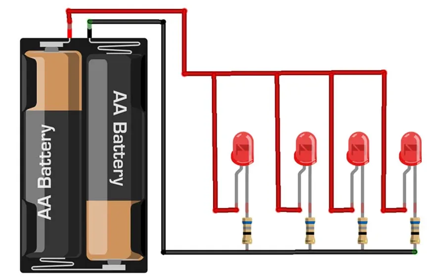
Parallel resistor configurations are fundamental in electronics, offering versatile solutions for current management, voltage control, and precise resistance tailoring. Their widespread use stems from the ability to reduce overall resistance and distribute current across multiple paths, enabling a range of applications from basic circuit design to complex electronic systems.
Here are some practical applications:
| Application | Description | Benefit |
|---|---|---|
| LED Arrays | Connecting multiple LEDs in parallel | Ensures even current distribution, preventing burnout |
| Custom Resistance | Combining standard resistors to achieve non-standard values | Enables precise circuit tuning |
| Current Limiting | Limiting the maximum current through a circuit | Circuit protection |
| Load Matching | Providing a specific load for a sensor or other component | Ensuring optimal signal integrity |
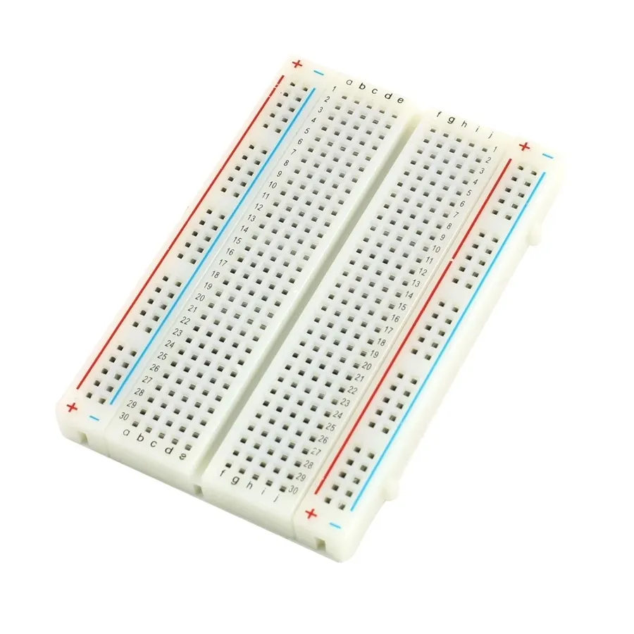
Understanding how to calculate equivalent resistance in parallel circuits is crucial for circuit design and analysis. This section provides step-by-step examples to demonstrate the application of the parallel resistance formula for circuits with varying numbers of resistors.
The core formula for calculating the total resistance (R_total) of parallel resistors is: 1/R_total = 1/R1 + 1/R2 + 1/R3 + ... + 1/Rn, where R1, R2, R3, ..., Rn are the resistances of each resistor in the parallel circuit. The following examples will show how to apply this formula in different scenarios.
Example 1: Two Resistors in Parallel
Let's consider a circuit with two resistors: R1 = 10 ohms and R2 = 20 ohms. To find the total equivalent resistance, we can use a simplified version of the formula (R_total = (R1 * R2) / (R1 + R2)), which gives R_total = (10 * 20) / (10 + 20) = 200/30 = 6.67 ohms.
| Parameter | Value |
|---|---|
| R1 | 10 ohms |
| R2 | 20 ohms |
| R_total | 6.67 ohms |
Example 2: Three Resistors in Parallel
Now let's calculate the total resistance for three resistors in parallel: R1 = 10 ohms, R2 = 20 ohms, and R3 = 30 ohms. Using the general formula: 1/R_total = 1/10 + 1/20 + 1/30 = 6/60 + 3/60 + 2/60 = 11/60. Therefore, R_total = 60/11 ≈ 5.45 ohms.
| Parameter | Value |
|---|---|
| R1 | 10 ohms |
| R2 | 20 ohms |
| R3 | 30 ohms |
| R_total | 5.45 ohms |
Example 3: More Than Three Resistors in Parallel
To extend the concept, consider a circuit with four parallel resistors: R1 = 10 ohms, R2 = 20 ohms, R3 = 30 ohms, and R4 = 40 ohms. Applying the formula: 1/R_total = 1/10 + 1/20 + 1/30 + 1/40 = 12/120 + 6/120 + 4/120 + 3/120 = 25/120. Thus, R_total = 120/25 = 4.8 ohms. Notice that adding more resistors in parallel decreases the total resistance.
| Parameter | Value |
|---|---|
| R1 | 10 ohms |
| R2 | 20 ohms |
| R3 | 30 ohms |
| R4 | 40 ohms |
| R_total | 4.8 ohms |
These examples illustrate that the total resistance in a parallel circuit is always less than the smallest individual resistance. It's also important to note that when resistors have different values, the current will take the path of least resistance, so a greater amount of current flows through the smaller resistors.
Troubleshooting parallel resistor circuits involves diagnosing issues that arise from component failure or incorrect circuit design. Understanding how parallel resistors affect current and voltage is key to effective troubleshooting.
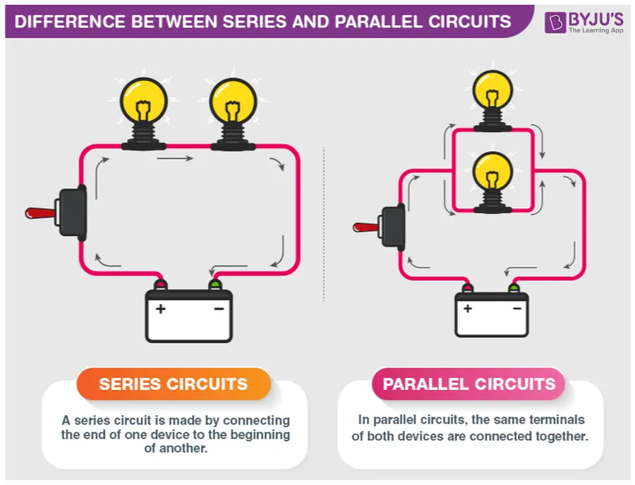
Understanding the fundamental differences between parallel and series resistor configurations is crucial for effective circuit design. These two configurations behave in distinctly different ways, impacting the total resistance, current flow, and voltage distribution within a circuit. This section provides a detailed comparison, highlighting key characteristics to distinguish their behavior.
| Feature | Series Resistors | Parallel Resistors |
|---|---|---|
| Connection | Resistors are connected end-to-end, forming a single path for current. | Resistors are connected side-by-side, providing multiple paths for current. |
| Total Resistance | Total resistance is the sum of individual resistances (R_total = R1 + R2 + R3 + ...). | Total resistance is less than the smallest individual resistance (1/R_total = 1/R1 + 1/R2 + 1/R3 + ...). |
| Current Flow | Same current flows through each resistor. | Current divides among parallel branches, with more current flowing through the paths of less resistance. |
| Voltage Distribution | Voltage drops across each resistor are proportional to their resistance. Total voltage is sum of individual voltage drops. | Voltage drop is same across each parallel resistor. |
| Effect of Adding Resistors | Adding a resistor increases total resistance. | Adding a resistor decreases total resistance. |
In series circuits, the current has only one path to follow, thus the current is the same through each resistor, and the total resistance is the sum of individual resistances. Conversely, parallel circuits provide multiple pathways for the current to flow, reducing the overall resistance, and ensuring each branch receives same voltage.
Adding parallel resistors is a core concept in electrical engineering, allowing designers to precisely control circuit behavior. By understanding the principles of parallel connections, you can manipulate the overall resistance, enabling the construction of more intricate and effective circuits. This knowledge is indispensable for anyone working with electronics and circuit design. Remember that the more resistors you add in parallel, the lower the total resistance becomes, demonstrating a counterintuitive yet fundamental principle of circuit design. Understanding this principle provides a foundation for more advanced circuitry concepts. Continue to explore and experiment with parallel resistors to fully unlock their potential.

