Transformers are the unsung heroes of modern electronics. From powering our smartphones to enabling complex industrial machinery, these seemingly simple devices play a crucial role in manipulating electrical energy. This article explores the world of transformers in electronics, explaining their function, various types, and why they are so essential to the devices that shape our lives. Let's demystify these ubiquitous components and understand their impact on everything from power distribution to signal processing.
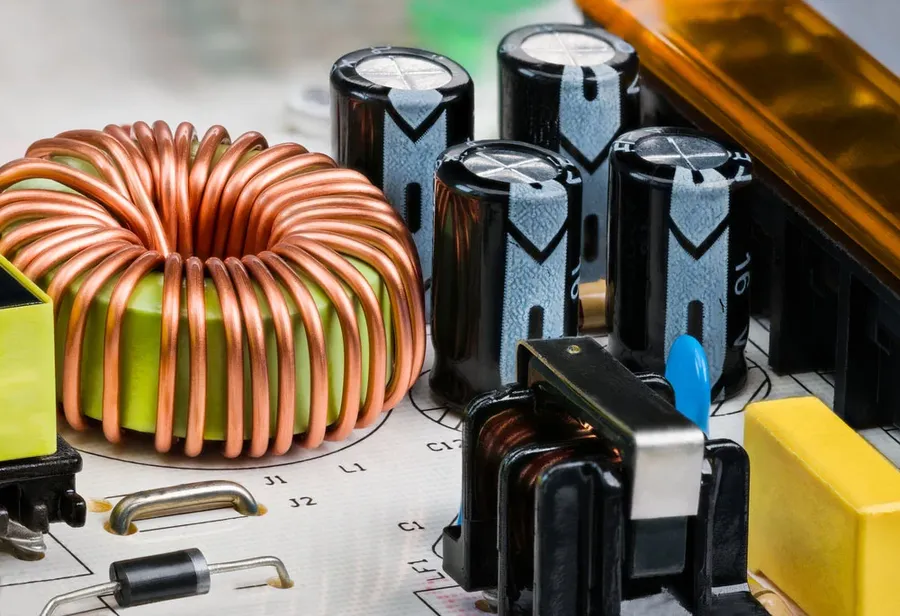
Transformers, essential components in electronics, operate based on the fundamental principle of electromagnetic induction. This process facilitates the transfer of electrical energy between circuits without any direct electrical connection, relying instead on the interaction between changing magnetic fields and conductive coils. At the heart of every transformer is the interplay between its primary and secondary coils, where variations in current induce a magnetic field that, in turn, generates a voltage in the secondary coil.
The core principle at play is Faraday's Law of Induction, which states that a time-varying magnetic field induces an electromotive force (EMF), or voltage, in a nearby conductor. In a transformer, an alternating current in the primary coil creates a changing magnetic flux within the core. This flux then passes through the secondary coil, inducing a voltage. This induced voltage can be stepped up or down, depending on the ratio of the number of turns in the primary and secondary coils.
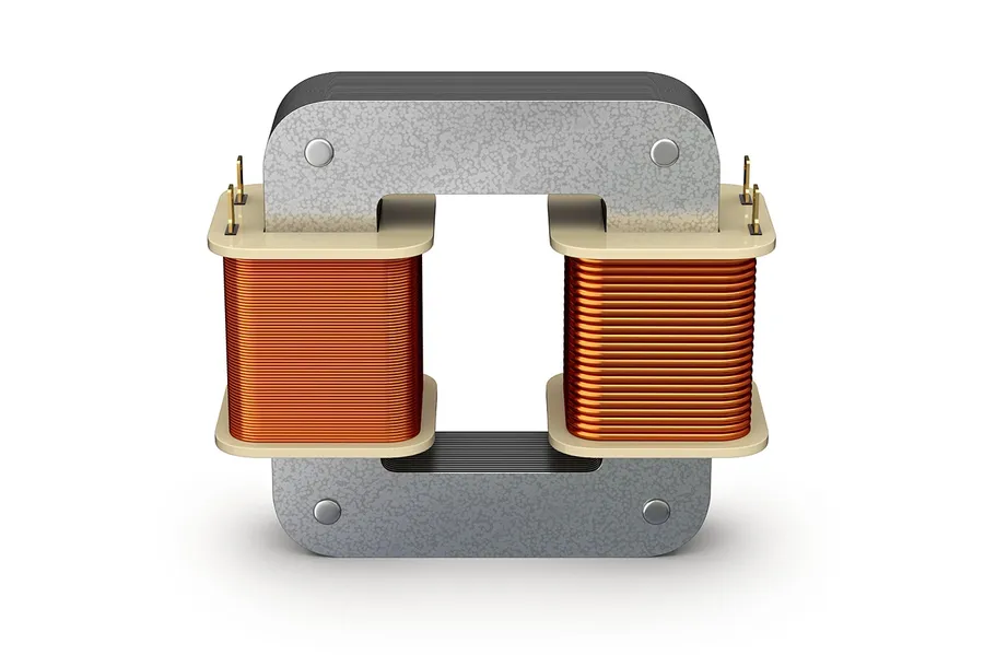
A transformer's functionality hinges on several key components working in concert. These components include the core, primary and secondary windings, and insulation, each playing a vital role in the efficient and safe transfer of electrical energy.
| Component | Material | Function |
|---|---|---|
| Core | Ferrite or Iron | Provides a low-reluctance path for magnetic flux |
| Primary Winding | Copper wire | Receives the input electrical energy |
| Secondary Winding | Copper wire | Delivers the transformed electrical energy |
| Insulation | Enamel coating, insulation tape | Prevents electrical shorts and ensures safe operation |
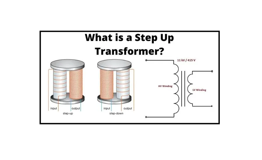
Transformers are fundamental components in electronics, primarily used to alter voltage levels in circuits. This is achieved through electromagnetic induction, where the transformer either increases (step-up) or decreases (step-down) the voltage, without altering the power significantly (disregarding losses). These transformations are crucial for adapting voltage levels for different parts of an electronic system or for efficient power transmission.
| Feature | Step-Up Transformer | Step-Down Transformer |
|---|---|---|
| Primary to Secondary Turns Ratio | Primary turns < Secondary turns | Primary turns > Secondary turns |
| Voltage Transformation | Increases Voltage (Vprimary < Vsecondary) | Decreases Voltage (Vprimary > Vsecondary) |
| Current Transformation | Decreases Current (Iprimary > Isecondary) | Increases Current (Iprimary < Isecondary) |
| Typical Application | High-voltage transmission or powering devices requiring higher voltage | Lowering voltage for electronic device operation |
The core principle governing voltage transformation is the turns ratio—the ratio of the number of turns in the secondary coil to the number of turns in the primary coil. Mathematically, this relationship is represented as Vp/Vs = Np/Ns, where Vp is the voltage across the primary coil, Vs is the voltage across the secondary coil, Np is the number of turns in the primary coil, and Ns is the number of turns in the secondary coil. This equation dictates that the voltage transformation is directly proportional to the turns ratio.
Importantly, it is vital to understand that while transformers change voltage, they ideally maintain power, neglecting losses, which can be expressed as P = V * I, where P is power, V is voltage, and I is current. Thus in a step-up transformer, as voltage increases, current decreases proportionally, and vice-versa in a step-down transformer.
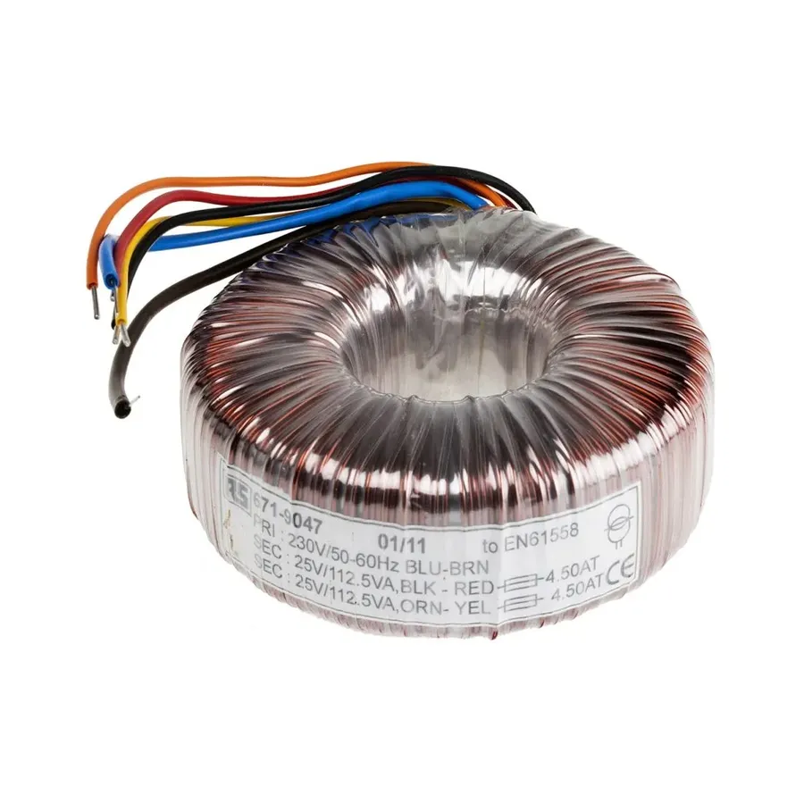
Transformers are indispensable components in electronic circuits, with various types designed for specific applications. These specialized transformers leverage different core materials, winding configurations, and construction techniques to meet diverse functional requirements such as power conversion, signal isolation, impedance matching and pulse shaping.
| Transformer Type | Application | Key Characteristics |
|---|---|---|
| Power Transformers | AC power conversion in power supplies, inverters, and industrial equipment. | Typically designed for high power handling, operating at 50/60Hz, may use laminated iron cores. |
| Isolation Transformers | Electrical isolation between circuits, preventing ground loops, and enhancing safety in sensitive electronic equipment. | Primary and secondary windings are electrically isolated, with high dielectric strength between windings. |
| Audio Transformers | Signal coupling and impedance matching in audio amplifiers and preamplifiers, impedance transformation between a high-impedance source and a low-impedance load such as a speaker. | Designed to operate within the audio frequency range (20Hz-20kHz), with low distortion characteristics, often use ferrite cores. |
| Pulse Transformers | Generating and transmitting pulses in digital circuits, gate drivers, and trigger circuits. | Optimized for fast rise times, low leakage inductance, suitable for high-frequency switching applications. |
| High-Frequency Transformers | Switch-mode power supplies, resonant converters, and high frequency inverters. | Operating at frequencies above 20 kHz, usually employ ferrite or powdered iron cores to minimize core losses. |
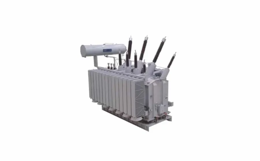
Selecting the correct transformer for an electronic circuit is critical for optimal performance and safety. This process involves careful consideration of several key parameters to ensure the transformer meets the specific application requirements. These criteria include voltage and current ratings, physical size constraints, operating frequency, impedance matching, and thermal characteristics.
| Selection Criteria | Description | Importance |
|---|---|---|
| Voltage Rating | Maximum voltage the transformer can safely handle. Includes both primary and secondary voltage. | Preventing insulation breakdown and ensuring safe operation; avoid overvoltage damage to circuit components. |
| Current Rating | Maximum current the transformer can handle without overheating or saturation. | Avoiding overheating and potential transformer damage; ensures stable current delivery to the load. |
| Size and Form Factor | Physical dimensions and shape of the transformer. | Meeting the constraints of the PCB or enclosure, fitting in space-limited applications. |
| Operating Frequency | Frequency at which the transformer is designed to operate optimally. | Maintaining efficiency and minimizing losses, particularly for high-frequency applications. |
| Impedance Matching | Ensuring the transformer's impedance matches the source and load impedances. | Achieving maximum power transfer and minimizing signal reflections, important for audio or communication signals. |
| Thermal Characteristics | Heat dissipation properties of the transformer and its thermal resistance. | Preventing overheating and thermal runaway, especially at high power levels, maintaining safe operating temperature. |
In practice, selecting a transformer begins with understanding the required voltage and current levels of the load. The transformer's primary and secondary voltage ratings should match the supply and load voltage requirements with appropriate margins. The current rating should also be sufficient to handle the load current without causing overheating. The physical size must also fit within the device. If the circuit involves high frequency operation, ensure that the core material and winding construction of the transformer are designed for that specific frequency.
Impedance matching, crucial in audio and communication circuits, requires a transformer with an impedance ratio that matches source and load impedances. This ensures maximum power transfer and minimal signal reflections. Additionally, the thermal characteristics of the transformer should be considered, especially when operating at higher power. A well-matched transformer provides long-term reliability and performance of the circuit it is installed in.
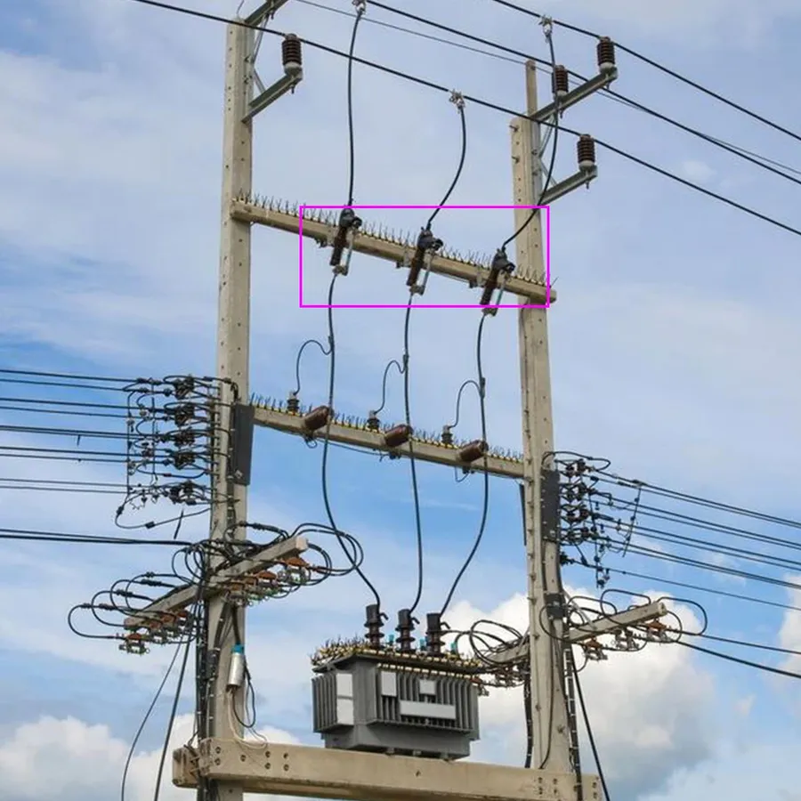
Ensuring safety when using transformers in electronic applications is paramount. This involves implementing protective measures against electrical hazards, thermal stress, and operational failures. Proper insulation, overcurrent protection, and effective earthing practices are crucial to prevent accidents, component damage, and system malfunctions. Additionally, understanding common failure modes allows for proactive mitigation strategies, enhancing the longevity and reliability of transformer-based systems.
Below are detailed considerations for safety and protection when utilizing transformers:
| Safety Measure | Description | Purpose |
|---|---|---|
| Insulation | Use of dielectric materials between conductive parts. | Prevents short circuits and electric shocks. |
| Overcurrent Protection | Installation of fuses or circuit breakers. | Protects against damage from excessive current. |
| Earthing | Providing a low-resistance path for fault currents. | Reduces electrical shock risk and dissipates fault currents. |
| Thermal Management | Using cooling methods like heat sinks or fans. | Prevents overheating and insulation degradation. |
This section addresses common queries regarding transformers in electronics, offering concise and technically sound answers to enhance understanding of their function, types, and applications.

The field of transformer technology for electronics is experiencing rapid evolution, driven by the demand for higher efficiency, smaller size, and greater integration capabilities. Innovations in materials science and advanced manufacturing techniques are pushing the boundaries of traditional transformer design, paving the way for more sophisticated applications.
Transformers are the workhorses of the electronics world, quietly enabling the power conversion and signal processing that drives our technological age. Understanding their fundamental principles, types, and applications is essential for anyone working with or interested in electronics. As technology continues to evolve, transformers will remain at the heart of many electronic systems, and future advancements in their design and materials will undoubtedly lead to further breakthroughs. So next time you pick up your phone or turn on a light, remember the vital role these unassuming devices play, and the world of 'transformers electronics' that they make possible.

