The ubiquitous hum of electronics around us is often powered by the silent work of transformers, and at the heart of many, lies the humble ferrite core transformer. This vital component, bridging the gap between electrical theory and practical application, efficiently transforms voltage and current levels. Much like the central nervous system of a device, a ferrite core transformer is responsible for the smooth operation of many modern electronic marvels, from power supplies to high frequency circuits. This article delves into the core of this technology, exploring its applications, design nuances, and advantages to give you a deeper understanding of these essential components.
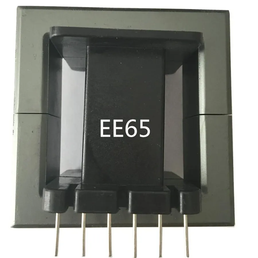
A ferrite core transformer is a type of transformer that utilizes a ferrite core, a ceramic material composed primarily of iron oxides combined with other metallic elements such as zinc, nickel, or manganese, to facilitate magnetic flux conduction. This core material is crucial for enhancing the transformer's performance, particularly at higher frequencies, by providing a low-reluctance path for the magnetic field. The selection of ferrite material is paramount as its specific magnetic properties directly influence the transformer's efficiency and operational characteristics.
The core is the central component of the transformer, around which the primary and secondary windings are placed. Ferrite cores are preferred in numerous applications because of their high permeability, which allows for stronger magnetic fields using fewer turns of wire. Moreover, ferrite cores are characterized by their high electrical resistivity which significantly reduces eddy current losses, making them suitable for use in high frequency applications. These key characteristics facilitate the transfer of electrical energy from the primary to secondary windings with minimal energy dissipation.

Ferrite cores offer significant advantages over other core materials, particularly laminated steel, in transformer applications. Their superior performance stems from a unique combination of high permeability, low eddy current losses, and efficient operation at high frequencies, making them ideal for modern electronic devices, especially high-frequency power converters.
| Feature | Ferrite Cores | Laminated Steel Cores |
|---|---|---|
| Permeability | High, allowing for efficient magnetic flux conduction | Lower, requires more material for same performance |
| Eddy Current Losses | Very low, minimizing heat generation and improving efficiency | Higher, leading to more heat generation and reduced efficiency, particularly at higher frequencies |
| Frequency Range | Excellent performance at high frequencies (kHz to MHz) | Performance degrades significantly at high frequencies due to increased eddy current losses |
| Core Loss | Low core loss, especially at high frequencies | Higher core loss, increasing at higher frequencies |
| Saturation Flux Density | Moderate, varies based on ferrite material composition | Higher saturation flux density |
| Cost | Generally cost-effective, especially for high volume production | Can be more expensive, especially for smaller and more complex geometries |
| Applications | Switched-mode power supplies, high-frequency inverters, and other compact electronic devices | Low frequency power transformers (50/60Hz) |
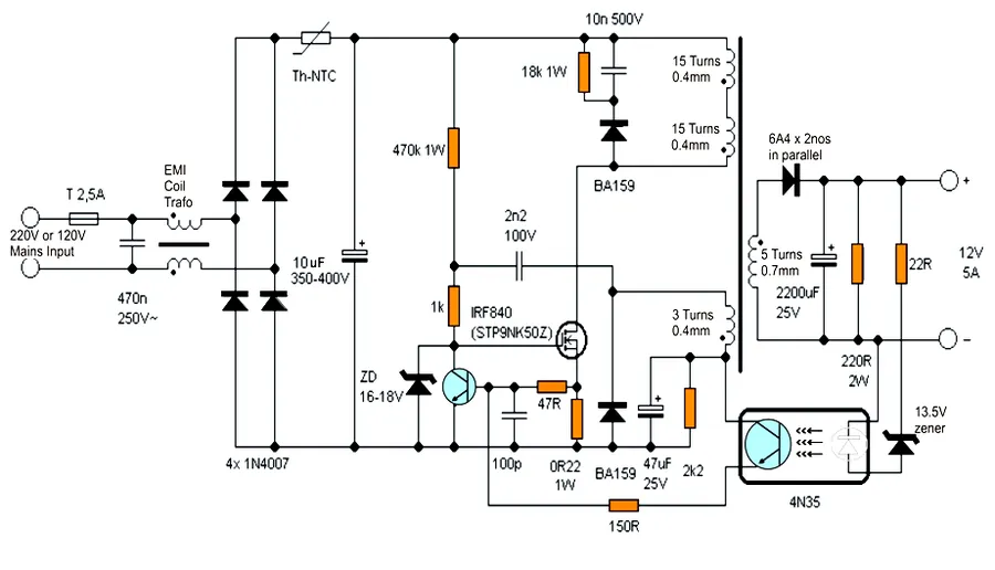
Ferrite core transformers are indispensable components in modern electronics due to their ability to operate efficiently at high frequencies, facilitating miniaturization and improved performance in various applications. Their unique magnetic properties make them ideal for use in systems where low loss and high efficiency are critical.
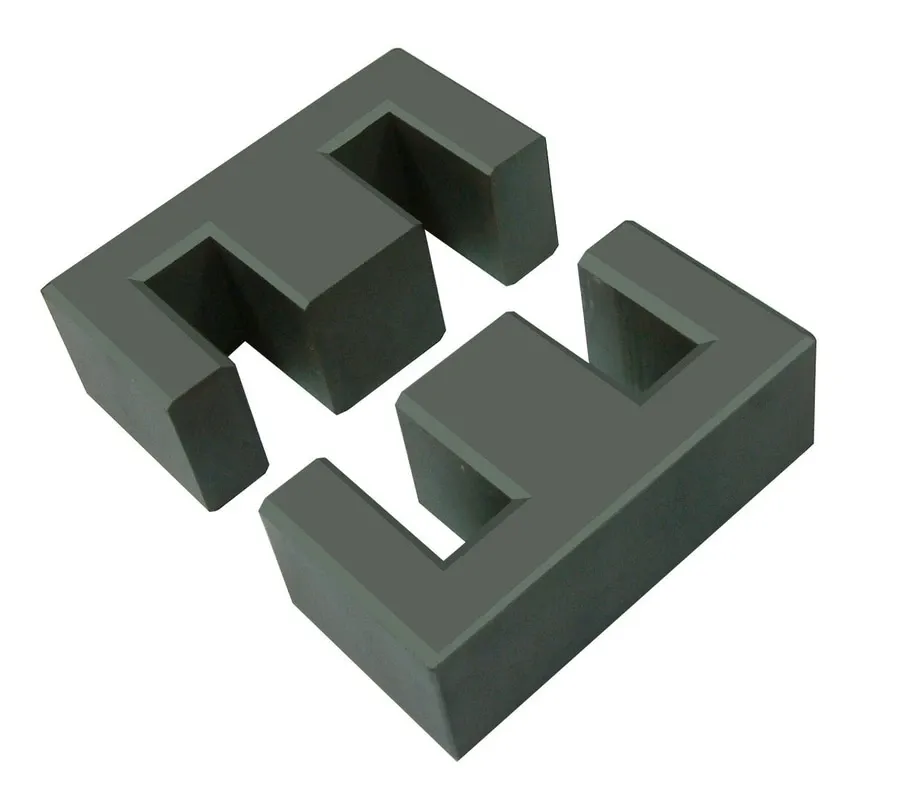
Ferrite cores, essential components in high-frequency transformers, are primarily composed of ceramic materials exhibiting unique magnetic properties. These materials are formed by combining iron oxides with other metallic oxides, resulting in a diverse range of ferrite types tailored to specific applications.
The chemical composition of a ferrite core is a critical factor that determines its magnetic behavior and suitability for various applications. The base of most ferrite cores consists of iron oxide (Fe2O3), which is then combined with one or more divalent metal oxides such as zinc oxide (ZnO), nickel oxide (NiO), manganese oxide (MnO), or magnesium oxide (MgO). The specific proportions and combinations of these oxides lead to various types of ferrites, each having a specific range of performance characteristics. These differences manifest in the ferrite's saturation magnetization, permeability, and temperature stability.
| Ferrite Type | Composition | Key Properties | Typical Applications |
|---|---|---|---|
| Manganese-Zinc (MnZn) | MnO, ZnO, Fe2O3 | High permeability, lower resistivity | EMI suppression, switching power supplies, common mode chokes |
| Nickel-Zinc (NiZn) | NiO, ZnO, Fe2O3 | High resistivity, lower permeability | High-frequency applications, antennas, wideband transformers |
| Magnesium-Zinc (MgZn) | MgO, ZnO, Fe2O3 | High Curie temperature, good temperature stability | Automotive, high-temperature applications |
| Copper-Zinc (CuZn) | CuO, ZnO, Fe2O3 | Cost effective, decent magnetic properties | General purpose transformers, low-cost solutions |
The manufacturing process and material selection directly affect the core's performance. For instance, MnZn ferrites are typically preferred for applications requiring high permeability and relatively lower frequencies, while NiZn ferrites are preferred for high-frequency applications due to their high resistivity which helps in minimizing eddy current losses.
Furthermore, variations in the microstructure, grain size, and density of the ferrite core also play a crucial role in determining its performance. Finer grain sizes typically lead to reduced core losses, while higher densities enhance magnetic properties and physical robustness. The selection of the appropriate ferrite material depends on a careful evaluation of the specific operating requirements, including frequency, temperature, and power levels.
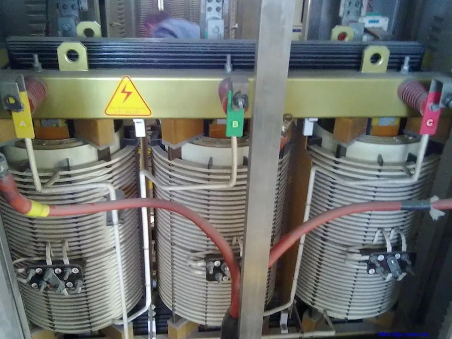
Effective design utilizing ferrite cores in transformers hinges on selecting the appropriate core and employing suitable winding techniques. This ensures optimal performance for specific power applications. Core selection depends on factors like power handling capacity and the 'WaAc' product, while winding methods greatly influence efficiency and minimizing losses.
The selection process must consider the power that the transformer will be required to handle, as different cores are designed with varying capabilities. This is essential in avoiding saturation, excessive heating, and ensuring efficiency. Furthermore, the physical dimensions of the core, and particularly the 'WaAc' product, (where Wa is the window area and Ac is the core's effective cross-sectional area) must be calculated accurately for the desired application. Choosing the proper winding techniques is essential for overall efficiency and performance.
| Parameter | Description | Impact on Performance |
|---|---|---|
| Power Handling Capacity | Maximum power the core can handle without saturation or excessive heating | Affects the maximum power output and efficiency of the transformer; selecting the appropriate core is crucial to prevent damage and inefficient operation. |
| WaAc Product (Window Area x Core Area) | Product of the core's window area and effective cross-sectional area. | Determines the maximum amount of copper winding that can be accommodated in the core, influencing transformer design and efficiency. |
| Winding Technique | Method used to wind the coil around the ferrite core (e.g., single-layer, multi-layer, bifilar). | Directly influences the transformer's parasitic capacitance, inductance, and resistance, affecting its frequency response, efficiency, and thermal management. |
| Core Material | Type of ferrite material and its properties. | Determines core loss at different frequencies. Selecting appropriate core material is essential for minimizing core loss and maximizing efficiency. |
| Operating Frequency | Frequency at which the transformer is intended to operate. | Influences core loss and the selection of core material and winding technique. Different materials behave differently at various frequencies. |
Selecting a ferrite core for a specific application involves a multi-faceted decision based on the required power levels, frequency of operation, and physical dimensions. In general, a higher WaAc value allows for a greater number of windings, which translates to more robust power transfer capabilities, this is a useful first step during component selection. For optimum performance, the core material needs to have low core losses at the desired operating frequency, as well as have a high saturation flux density. Winding techniques, such as layer winding, bobbin winding, and planar windings, influence the leakage inductance and parasitic capacitance. Minimizing parasitic effects is a key step to reducing signal loss and improve overall performance. The proper winding selection can contribute to a significant increase in a transformer’s efficiency.
Ferrite core transformers exhibit optimal performance within specific frequency ranges, primarily due to the material's inherent magnetic properties and how they interact with alternating magnetic fields. Understanding these frequency-dependent characteristics is crucial for effective transformer design and application. This section details the relationship between operating frequency, core loss, and transformer efficiency.
| Frequency Range | Core Material Behavior | Typical Applications | Notes |
|---|---|---|---|
| Low Frequencies ( < 10 kHz) | Ferrite cores are generally not optimal; higher losses may occur due to hysteresis. | Not a common application for ferrite cores; laminated steel cores often preferred. | Core losses become significant at low frequencies. Choose other materials like laminated steel instead. |
| Medium Frequencies (10 kHz - 1 MHz) | Ferrite cores excel, exhibiting low losses and high permeability. | Switching power supplies, inverters, electronic ballasts. | This is the typical operational range of ferrite core transformers. |
| High Frequencies (1 MHz - 10 MHz) | Ferrite cores continue to be effective, though core losses begin to rise with frequency. Careful material and design choices are critical. | High-frequency SMPS, radio frequency (RF) circuits. | Material selection is important, since higher frequency operation demands careful management of parasitic effects. |
| Very High Frequencies ( > 10 MHz) | Core losses become very significant, and specialized materials may be necessary. Ferrite cores may reach their practical limit. | Specialized RF applications, high-speed data transmission | Use other materials like amorphous metal or air core designs. |
Core loss, also known as iron loss, is a critical parameter that significantly impacts the efficiency of a ferrite core transformer. This loss is primarily due to two components: hysteresis loss and eddy current loss. Hysteresis loss is a result of the energy required to repeatedly magnetize and demagnetize the core material, and it is proportional to the frequency of operation. Eddy current loss arises from circulating currents induced in the core material by the changing magnetic field, which is also frequency-dependent, increasing dramatically as the frequency increases. These losses manifest as heat, reducing overall efficiency and potentially requiring thermal management.
The efficiency of a ferrite core transformer is heavily influenced by the balance between the core's performance characteristics at various frequencies and its intended use. Proper core material selection, precise core design, and winding techniques must be employed to minimize losses and optimize the transfer of energy. Transformer designers should carefully consider the specific frequency range of the application to fully leverage the inherent advantages of ferrite core materials.
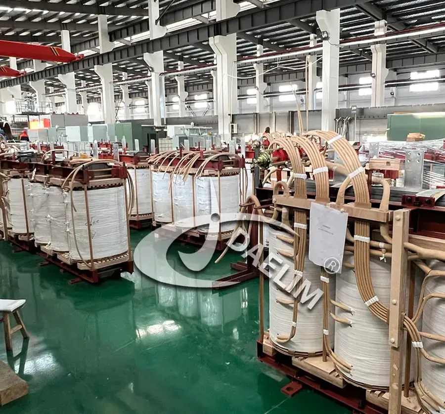
The manufacturing process of ferrite cores for transformers is a carefully controlled sequence of steps that transforms raw materials into high-performance magnetic components. This process involves precise material preparation, shaping, sintering, and finishing to achieve the desired electrical and mechanical properties.
The process typically consists of the following key stages:
Quality control is an integral aspect of the ferrite core manufacturing process. Testing is conducted at multiple stages from material mixing to final packaging to guarantee each core meets performance and reliability standards. This rigorous quality control ensures the overall efficiency and longevity of the ferrite core in transformer applications.
This section addresses common queries regarding ferrite core transformers, providing practical insights into their applications, performance characteristics, and optimal usage.
Ferrite core transformers, while robust, can encounter issues that impact their performance. Proper troubleshooting and maintenance are crucial for ensuring reliable and long-lasting operation. This section provides practical guidance on identifying common problems, diagnosing their root causes, and implementing preventive maintenance strategies.
Ferrite core transformer issues typically fall into two categories: electrical and mechanical. Electrical issues often stem from winding faults, insulation breakdown, or core saturation. Mechanical problems may involve core cracking, physical damage to windings, or loose connections. A methodical approach to diagnosing these problems is crucial for effective repairs.
Preventive maintenance is critical for prolonging the life of ferrite core transformers. Routine inspections should include visual checks for damage, cleaning to remove dust and contaminants, and ensuring proper ventilation to manage heat dissipation. Regularly measure winding resistance, leakage inductance, and dielectric strength. For critical applications, consider a scheduled replacement program to minimize unexpected failures.
Troubleshooting should involve systematically isolating components. First, check the input voltage and current for abnormalities, next examine the winding connections for issues, and last verify the core condition. Use electrical measurement devices, such as multimeters, LCR meters, and oscilloscopes, to assess circuit performance. Consider that changes in the operating environment, such as temperature and humidity, can have a notable impact. Always disconnect the transformer from the power source before performing any maintenance or troubleshooting activities.
Ferrite core transformers are indispensable components that quietly work to power our modern world, from the smallest handheld devices to the largest industrial machinery. These magnetic marvels, built around their ferrite cores, are selected for their high-frequency efficiency and low eddy current losses making them ideal for a wide range of uses. By understanding their design, advantages, and limitations, designers and engineers can harness their capabilities to create more efficient and reliable systems. As technology continues to advance, so too will the role of ferrite core transformers evolve, ensuring that they remain a cornerstone of electronic innovation for years to come.

