In the intricate world of electronics, efficiency and space-saving are paramount. The humble resistor array, a seemingly simple component, plays a pivotal role in achieving these goals. From the microchips powering our smartphones to the complex circuits of industrial machinery, resistor arrays are the unsung heroes, streamlining designs and enhancing performance. This article demystifies these essential components, revealing how a seemingly simple collection of resistors can profoundly impact circuit functionality and design simplicity.
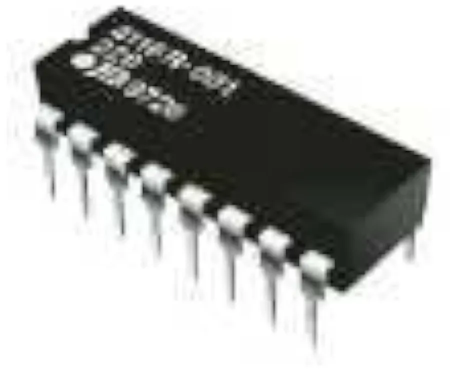
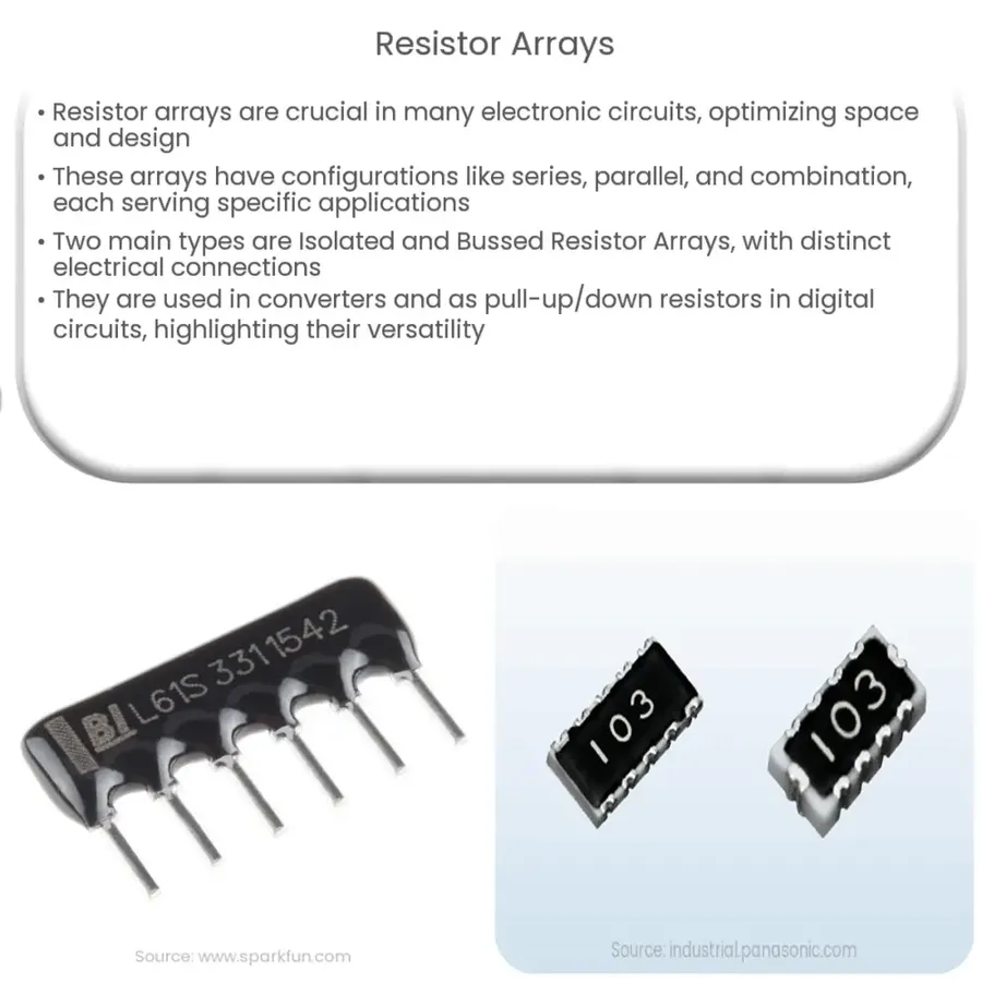
A resistor array, also known as a resistor network, is an integrated component housing multiple individual resistors within a single, compact package. This arrangement provides a space-saving alternative to using numerous discrete resistors, streamlining circuit design and assembly processes. These arrays are available in various configurations and are fundamental components in a wide range of electronic applications.
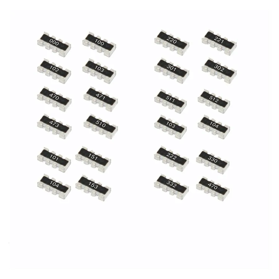
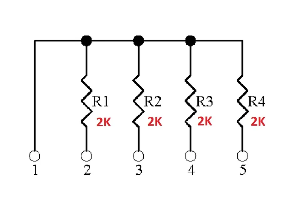
Resistor arrays, also known as resistor networks, come in several configurations, each designed for specific applications. The three primary types are isolated resistors, common connection (also called common bus), and dual termination. These configurations offer varying levels of flexibility and are crucial for optimizing circuit design.
| Configuration | Description | Typical Application |
|---|---|---|
| Isolated Resistors | Each resistor is independent with no shared connections | Multiple distinct biasing networks in a single package |
| Common Connection | One terminal of all resistors is connected to a common bus | Pull-up or pull-down resistor networks |
| Dual Termination | Two resistors per connection node | Transmission line termination to match the characteristic impedance |
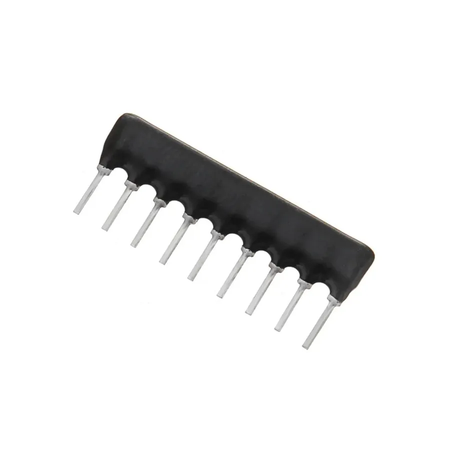
Resistor arrays are available in two primary mounting styles: Surface Mount Devices (SMD) and Through-Hole. Each type offers distinct advantages and disadvantages, influencing their application in electronic circuit design and assembly. The choice between SMD and through-hole resistor arrays significantly impacts PCB layout, assembly processes, and overall system performance. Understanding these differences is crucial for efficient and effective design implementation.
| Feature | SMD Resistor Arrays | Through-Hole Resistor Arrays |
|---|---|---|
| Mounting Method | Soldered directly onto the surface of the PCB | Leads inserted through holes in the PCB and soldered on the opposite side |
| Size | Significantly smaller, allowing for higher component density | Larger physical size, requiring more PCB real estate |
| Assembly | Automated assembly using pick-and-place machines and reflow soldering | Can be manually assembled or using wave soldering, suitable for prototyping and small-scale production |
| PCB Design | Simplified layout with pads only, often requiring less board space | Requires drilled holes for lead insertion, leading to more complex board routing and design |
| Thermal Performance | Generally better thermal performance due to direct contact with the PCB, enabling efficient heat dissipation | Potentially lower thermal performance due to the insulation of leads |
| Mechanical Strength | More susceptible to damage if subjected to significant mechanical stress. | More robust and can withstand greater mechanical stress |
| Ideal Use Cases | High-density consumer electronics, portable devices, and mass production applications | Prototyping, educational projects, applications needing higher mechanical integrity, or when manual assembly is preferable |
| Cost | Lower cost at scale due to automation suitability. | Potentially higher cost for high-volume production due to less automated process and larger size. |

Resistor arrays offer significant advantages over discrete resistors in many electronic applications, primarily due to their integrated nature. These benefits include space saving, reduced part count, faster assembly, improved thermal performance, and reduced overall board costs.
Resistor arrays, due to their compact nature and precise matching, find widespread use in electronic circuits. They streamline design, simplify manufacturing, and enhance performance across diverse applications. The following discussion provides an in-depth view of these common applications.
Interpreting resistor array datasheets accurately is crucial for selecting the correct component for a given application. These datasheets contain key parameters that define the electrical and physical characteristics of the array. Understanding these specifications ensures optimal circuit performance and reliability. These parameters include resistance values, tolerances, power ratings, temperature coefficients, and package types, all of which are detailed below.
| Parameter | Description | Importance for Selection |
|---|---|---|
| Resistance Value | The nominal resistance of each individual resistor within the array, typically measured in ohms (Ω). | Ensures the correct resistance for circuit function (e.g., voltage division, current limiting). |
| Tolerance | The maximum deviation of the actual resistance value from its nominal value, typically expressed as a percentage (+/- %). | Affects accuracy of the circuit and determines the performance variations. |
| Power Rating | The maximum power that each resistor in the array can dissipate without being damaged, usually measured in watts (W). | Prevents resistor failure from overheating. Crucial for reliability, and must be greater than expected usage. |
| Temperature Coefficient | The change in resistance per degree Celsius (°C) temperature change, often measured in parts per million per degree Celsius (ppm/°C). | Critical for stability across a range of operating conditions; significant for precise analog circuits. |
| Package Type | The physical form of the resistor array, such as SMD (Surface Mount Device) or through-hole. | Impacts the PCB layout, assembly process, and size restrictions. |
| Number of elements | The quantity of individual resistors contained within the array package. | Determines how many functions the single component can fulfill. |
| Maximum voltage | The maximum voltage the array can withstand. | Ensures the resistor is not damaged from exceeding the maximum voltage. |
When choosing a resistor array for a specific application, carefully consider the following parameters. For example, precision applications require lower tolerance and temperature coefficient values. High-power applications demand larger power ratings. The package type must be compatible with the board design and assembly process. Always refer to datasheets and understand the application specific requirements.
The selection between resistor arrays and discrete single resistors hinges on a careful evaluation of circuit requirements, design priorities, and practical constraints. While single resistors offer flexibility and granularity in value selection, resistor arrays provide compactness and efficiency when multiple resistors are required, especially with similar values.
| Feature | Resistor Array | Single Resistors |
|---|---|---|
| Space Efficiency | High; multiple resistors in one package | Low; each resistor requires individual space |
| Part Count | Lower; simplifies BOM and assembly | Higher; increases BOM complexity |
| Assembly Time | Faster; pick-and-place of a single component | Slower; requires mounting multiple components |
| Cost | Potentially lower at high volumes; economies of scale | Potentially higher overall system cost when considering assembly |
| Design Flexibility | Limited by the predefined configuration | High; can select any value and combination |
| Component Handling | Easier to handle and mount | Requires more careful handling and placement of multiple components |
| Ideal Use Case | Multiple resistors of the same or similar value, such as pull-ups, pull-downs, voltage dividers | Circuits with unique and various resistor values, or very high precision requirements |
In essence, if your design incorporates numerous resistors of the same or similar value, particularly in pull-up, pull-down, or voltage divider configurations, a resistor array offers significant advantages in terms of board space, assembly efficiency, and potentially cost. However, for designs demanding high precision or widely varied resistor values, individual components may be the more suitable approach.
This section addresses common questions regarding resistor arrays, providing clear and concise answers to enhance your understanding and application of these components in electronic circuits.
In conclusion, resistor arrays are indispensable components in modern electronics, offering a compelling solution for efficient circuit design, particularly in space-constrained applications. By understanding their varied types, advantages, and applications, and paying attention to the critical specifications in datasheets, engineers and hobbyists can harness the power of resistor arrays to create optimized, high-performing, and cost-effective circuits. The continuous advancements in resistor array technology promise to make them even more crucial for future electronic innovations. Whether you are working on a simple LED circuit or a complex communication module, considering the use of a resistor array can be a game-changer in terms of performance and design efficiency.

