In the realm of power electronics, the Silicon Controlled Rectifier (SCR), is pivotal in controlling high voltage and power. These devices, also known as thyristors, are vital in various electronic applications. From industrial motor control to sophisticated power supplies, SCR electronics plays a critical role, bridging the gap between power and precision. This article provides an in-depth look at SCRs, unraveling their unique characteristics and diverse uses.
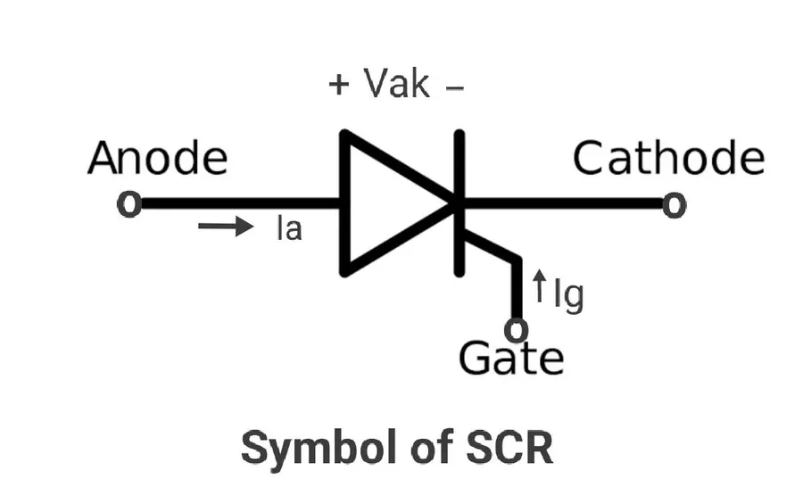
A Silicon Controlled Rectifier (SCR) is a three-terminal semiconductor device that functions as a unidirectional electronic switch. Critically, it permits current flow in only one direction, analogous to a diode, but with the addition of a gate terminal to enable control of its switching behavior. SCRs are a specific type of thyristor, a class of power electronics components crucial in various electronic circuits.
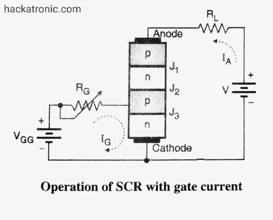
Silicon Controlled Rectifiers (SCRs) are fundamental components in power electronics, characterized by their unique four-layer semiconductor structure and a distinctive circuit symbol. This structure and symbol are critical for understanding how SCRs function and for their correct implementation in electronic circuit design.
The structure of an SCR comprises four alternating layers of P-type and N-type semiconductor material. These layers form three PN junctions. Specifically, the layers are arranged as P-N-P-N, resulting in the following configuration: Anode (P-type), followed by a N-type layer, then another P-type layer, and finally the Cathode (N-type). This four-layer design enables the SCR's unidirectional current conduction capabilities and controlled switching characteristics.
The SCR symbol is a standardized representation used in electronic schematics to depict the device. It features three terminals: the Anode (A), the Cathode (K), and the Gate (G). The Anode and Cathode form the primary current path, similar to a diode, and the Gate is the control terminal. The symbol itself visually indicates the direction of current flow, with an arrowhead pointing from the Anode towards the Cathode.
| Feature | Description |
|---|---|
| Semiconductor Layers | Alternating P-type and N-type materials in a P-N-P-N configuration |
| PN Junctions | Three PN junctions are formed between the semiconductor layers |
| Terminals | Anode (A), Cathode (K), Gate (G) |
| Symbol Representation | Indicates unidirectional current flow and the control gate. |
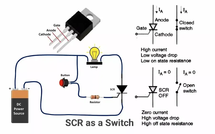
The fundamental operation of a Silicon Controlled Rectifier (SCR) hinges on its ability to act as a unidirectional switch, remaining in a non-conducting state until triggered. This triggering mechanism, initiated by a positive gate pulse, propels the SCR into a conducting state where it allows current to flow. This state continues until the current drops below a certain threshold known as the holding current, highlighting its role in controlling current flow within SCR electronics.
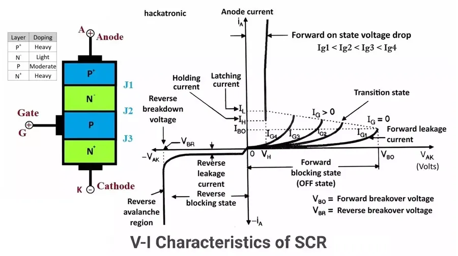
Understanding the characteristics and parameters of Silicon Controlled Rectifiers (SCRs) is crucial for effective design and application in power electronics. These parameters dictate how an SCR will behave under various conditions, and proper selection based on these parameters is essential for reliable circuit performance. Key parameters include forward blocking voltage, forward current, holding current, and gate trigger current, each influencing different aspects of SCR operation within SCR electronics.
| Parameter | Description | Impact on SCR Operation |
|---|---|---|
| Forward Blocking Voltage (VDRM) | The maximum forward voltage an SCR can withstand in the off-state without conducting. | Ensures the SCR does not unintentionally switch on due to high voltage, crucial for preventing damage and misoperation. |
| Forward Current (IT) | The maximum continuous current an SCR can safely carry in the on-state. | Determines the SCR's current handling capability; exceeding it can cause overheating and failure. |
| Holding Current (IH) | The minimum current required to maintain the SCR in the conducting state. | Once the SCR is triggered, current must stay above this threshold to remain on, which determines minimum operating current. |
| Gate Trigger Current (IGT) | The minimum current required at the gate terminal to trigger the SCR into the on-state. | Dictates the sensitivity of the SCR to trigger signals, which influences triggering circuit design. |
| Gate Trigger Voltage (VGT) | The minimum voltage required at the gate terminal to trigger the SCR into the on-state. | Works in conjunction with gate trigger current, influencing the design of the triggering circuit. |
| Turn-on Time (ton) | The time it takes for the SCR to switch from the off-state to the on-state. | Critical in high-frequency applications, determining the operating speed of the SCR. |
| Turn-off Time (toff) | The time it takes for the SCR to switch from the on-state to the off-state. | Important in AC circuits, influencing the speed at which the SCR can block voltage after conduction. |
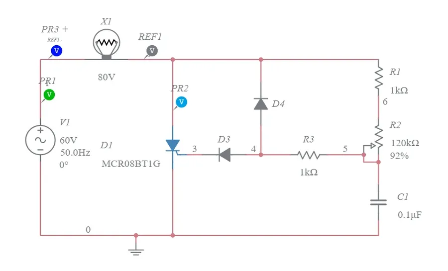
The operational control of a Silicon Controlled Rectifier (SCR) in electronic circuits hinges on the ability to precisely trigger it into conduction and then, crucially, to return it to a non-conducting state. Understanding these turn-on and turn-off mechanisms is fundamental for effective use in SCR electronics. SCRs are not simply on/off switches, they are more precisely controllable power control devices.
| Turn-On Method | Turn-Off Method |
|---|---|
| Positive Gate Current Pulse | Reduce Anode-Cathode Current below Holding Current |
| Once triggered, no gate signal required | Reverse Voltage Bias (in some cases) |
| External Switch to force current below holding current |
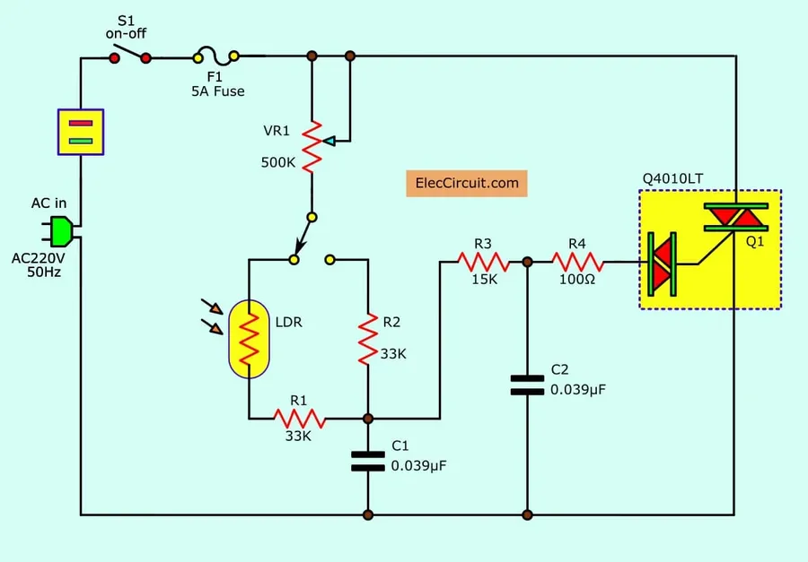
Silicon Controlled Rectifiers (SCRs) are pivotal components in power electronics, enabling efficient and reliable control of electrical power. Their unidirectional conduction and latching behavior make them ideal for a wide array of applications where precise power modulation is needed.
Silicon Controlled Rectifiers (SCRs) are robust semiconductor devices with significant advantages in specific applications, particularly in power electronics. However, they also present certain limitations that must be considered during design. Understanding both the pros and cons is crucial when incorporating SCRs into electronic circuits.
| Advantages | Limitations |
|---|---|
| High current and voltage handling | Unidirectional conduction |
| Rugged and reliable | Slow switching speeds |
| Simple control circuitry | Requires current to drop below holding current to turn off |
This section addresses common queries regarding Silicon Controlled Rectifiers (SCRs), elucidating their function, operation, and applications within the realm of SCR electronics. The goal is to provide clear, concise answers to typical questions that arise when working with these power control devices.
SCR electronics plays a fundamental role in power management, offering solutions for controlling high voltages and currents, this is especially essential for various industrial and domestic applications. From simple switches to advanced motor controls, SCRs demonstrate their versatility and importance in SCR electronics. As technology evolves, SCRs remain a critical element in power electronic systems, highlighting their continuing relevance in the field.

