In our daily lives, we rely heavily on efficient electrical systems to power our homes and industries. Often unseen, a critical component ensuring this efficiency is the humble shunt capacitor. Like a seasoned athlete, shunt capacitors enhance power factor, reduce energy loss, and ensure the smooth operation of electrical systems. This article will illuminate the function, benefits, and applications of these essential devices, bridging the gap between complex engineering and practical understanding.
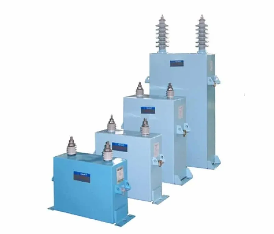
A shunt capacitor, fundamentally, is a capacitor that is connected in parallel with an electrical load or power source within a circuit. This configuration allows it to act as a localized source of reactive power, counteracting the effects of inductive loads and thereby improving the overall power factor of the system. The parallel connection is key to its function, facilitating the flow of reactive current between the capacitor and the load.
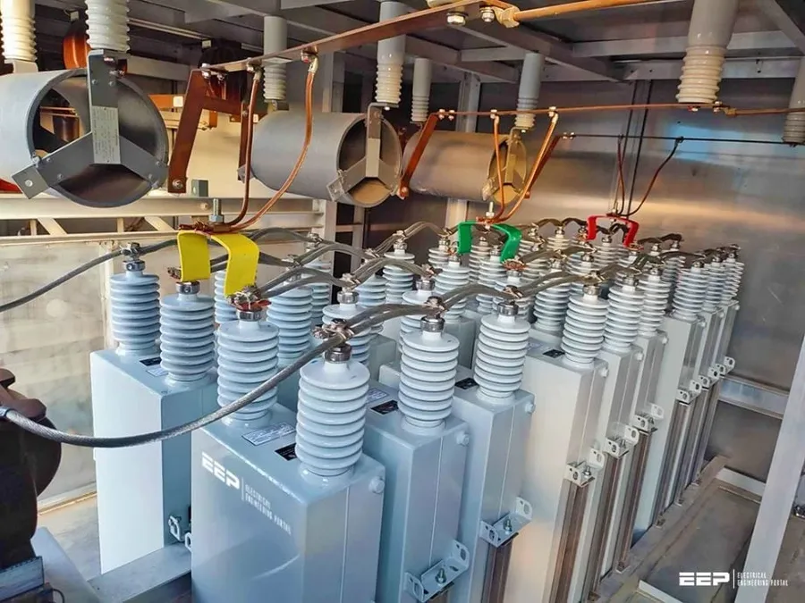
Shunt capacitors are fundamental components in electrical systems, strategically employed to enhance power factor by counteracting the effects of inductive loads. They achieve this by providing reactive power, which is crucial in alternating current (AC) circuits where inductive elements like motors and transformers draw both active (real) and reactive power.
A low power factor indicates inefficient use of electrical power, leading to higher energy consumption and costs. Inductive loads cause a phase difference between voltage and current, resulting in reactive power demand that the power grid must supply. Shunt capacitors effectively act as local sources of reactive power, reducing the burden on the grid and improving the overall power factor.
By supplying reactive power, shunt capacitors reduce the current required from the grid to deliver the same amount of active power. This reduction in current minimizes losses in the transmission and distribution lines due to resistive heating (I²R losses), resulting in a more efficient use of electrical energy and a reduction in overall electricity costs.
| Aspect | Effect without Shunt Capacitors | Effect with Shunt Capacitors |
|---|---|---|
| Reactive Power Demand | High, drawn from the grid | Reduced, supplied locally |
| Power Factor | Low, inefficient power use | Improved, more efficient power use |
| Current Draw | Higher, leading to losses | Lower, reducing losses |
| Energy Consumption | Higher for the same work | Lower for the same work |
| System Capacity | Lower capacity utilization | Increased capacity utilization |
| Transmission Losses | Higher losses due to increased current | Reduced losses due to lower current |
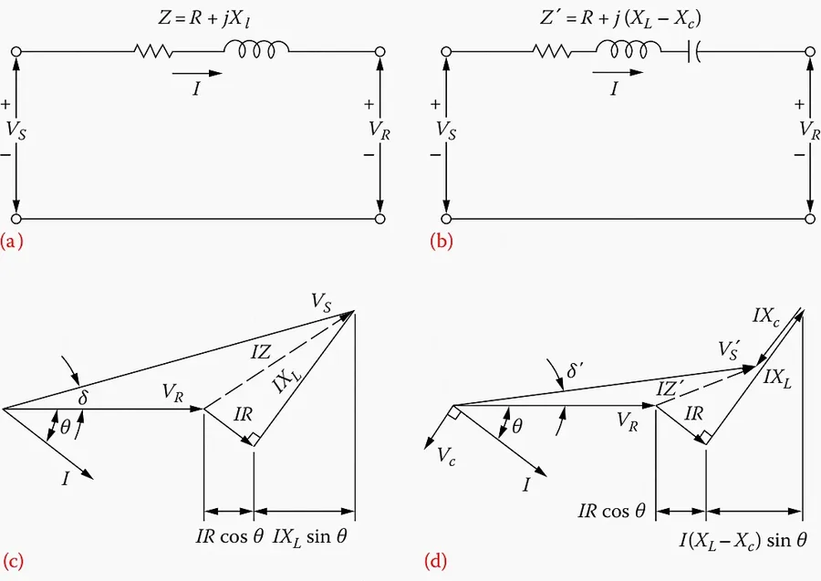
Shunt and series capacitors, while both being capacitive elements, are deployed in electrical circuits for fundamentally different purposes. Shunt capacitors are connected in parallel with a load or a power source, primarily for power factor correction, whereas series capacitors are connected in series with the line, mainly for voltage regulation and improving the transmission capacity of power lines. These differences in connection topology dictate their distinct roles and applications within the electrical system.
| Feature | Shunt Capacitor | Series Capacitor |
|---|---|---|
| Connection | Parallel with load or source | Series with the line |
| Primary Function | Power factor correction and reactive power compensation | Voltage regulation and improve transmission capacity |
| Impact on Current | Reduces current drawn from source by providing reactive power locally | Reduces line impedance and increases current flow capability |
| Impact on Voltage | Maintains voltage stability at the load | Impacts voltage by directly counteracting line inductance |
| Typical Application | Distribution networks, industrial facilities, and electronic circuits | High-voltage transmission lines |
| Failure Mode | Typically results in overvoltage at the connected load if not appropriately protected. | Can lead to overcurrent and line instability if not properly coordinated with other line protection equipment. |
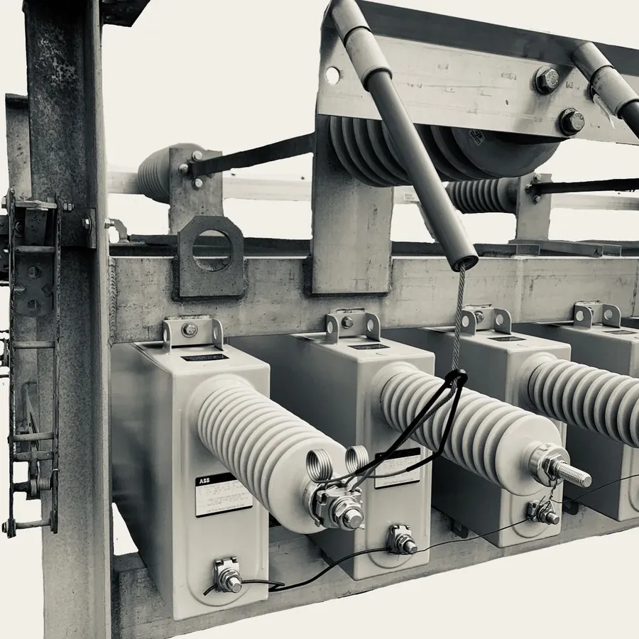
Shunt capacitors significantly enhance the efficiency of electrical systems by addressing the issue of reactive power. By providing a localized source of reactive power, they reduce the burden on the utility grid, leading to lower current draw, reduced line losses, and an overall increase in system capacity. This results in lower energy consumption, reduced costs, and improved system stability.
| Parameter | Impact of Shunt Capacitors | Explanation |
|---|---|---|
| Reactive Power | Reduced | Shunt capacitors supply reactive power locally, minimizing the demand on the grid. |
| Current Draw | Lowered | Reduced reactive power demand leads to a lower overall current draw from the source. |
| Line Losses | Minimized | Lower current reduces resistive losses (I²R) in the conductors. |
| System Capacity | Increased | By reducing reactive power needs, available capacity is increased to handle more active power load. |
| Energy Consumption | Reduced | Lower line losses and current draw translate to reduced energy consumption. |
| Costs | Lowered | Reduced energy consumption and reactive power charges result in reduced operational costs. |
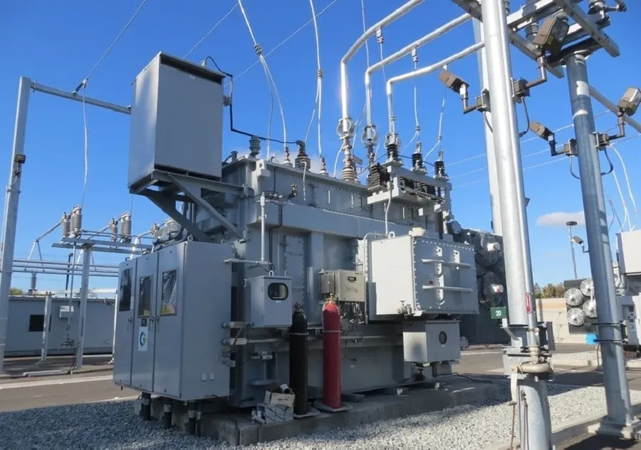
Shunt capacitors are integral components across diverse sectors, playing a crucial role in maintaining power quality and enhancing the efficiency of electrical systems. Their application spans from large-scale power distribution networks to intricate electronic circuits.
Selecting the appropriate shunt capacitor is critical for optimal performance and system reliability. This process requires a thorough understanding of various factors, including voltage requirements, capacitance ratings, and the specific characteristics of the electrical system it is intended to serve. Improper selection can lead to inefficiencies, equipment damage, or system instability.
| Parameter | Description | Units | Importance |
|---|---|---|---|
| Rated Voltage | The maximum voltage the capacitor can withstand continuously. | Volts (V) | Critical for preventing dielectric breakdown and ensuring safe operation. |
| Capacitance | The measure of a capacitor’s ability to store electrical charge. | Farads (F), Microfarads (µF), Nanofarads (nF) | Determines the amount of reactive power compensation provided by the capacitor. |
| Reactive Power Rating | The amount of reactive power the capacitor is designed to provide. | Volt-Ampere Reactive (VAR) | Must match the reactive power demand to achieve desired power factor improvement. |
| Operating Temperature | The range of ambient temperatures within which the capacitor is designed to function reliably. | Celsius (°C) | Affects the capacitor's performance and lifespan. Exceeding operating temperature can cause damage. |
| Tolerance | The allowable variation in the actual capacitance value from its nominal rated value. | Percentage (%) | Ensures that the installed capacitance is within acceptable range. |
| Dielectric Type | The material used as an insulator between the capacitor plates. | N/A | Influences the capacitor's temperature stability, lifespan, and cost. |
| Construction Type | How the capacitor is constructed, such as oil-filled or dry type | N/A | Impacts the capacitor's size, weight, and thermal dissipation capability. |
The selection process should begin with a precise assessment of the electrical system's parameters. Key considerations should include not just the voltage level but also the harmonic content which affects the capacitor’s performance and lifespan. Also, the expected operating conditions like ambient temperature, humidity, and the environment, should be evaluated. This thorough analysis helps in selecting a capacitor with the necessary safety margin and the performance needed for the application, thus ensuring optimal performance and longevity of the installed equipment.
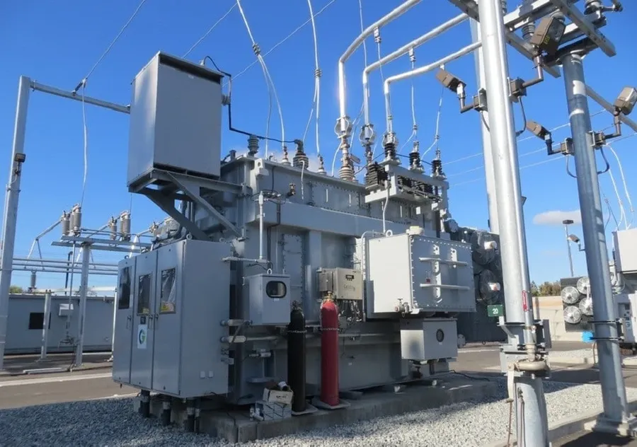
Shunt capacitors are critical components in modern electrical transmission lines, strategically deployed to enhance voltage stability, facilitate efficient long-distance power delivery, and minimize transmission losses. Their presence is vital for maintaining the integrity and reliability of the power grid.
| Function | Impact on Transmission Lines |
|---|---|
| Voltage Stability | Reduces voltage fluctuations, maintaining steady voltage levels along the line. |
| Long Distance Transmission | Compensates for reactive power losses, allowing efficient power transfer over long distances. |
| Reduced Transmission Losses | Decreases reactive power flow in the line, leading to reduced I²R losses and improved efficiency. |
| Grid Stability | Supports grid reliability by maintaining stable voltage levels and reducing the risk of voltage collapse. |
This section addresses common queries about shunt capacitors, clarifying their function and application in electrical systems. We aim to provide clear and concise answers to enhance your understanding of these important components.
Effective utilization of shunt capacitors requires careful consideration of their application, maintenance, and potential troubleshooting. This section provides practical guidance to ensure optimal performance and longevity of these critical power system components.
Shunt capacitors are fundamental components for ensuring efficient and reliable electrical systems, acting as silent heroes to boost power factor, reduce losses, and enhance voltage quality. From industrial applications to transmission grids, the widespread use of shunt capacitors reflects their importance. A solid understanding of shunt capacitor principles can be beneficial to both engineers and those wanting to understand the basics of modern electrical systems. With their broad applications, shunt capacitors are essential components in maintaining a robust and efficient power infrastructure, underscoring the critical importance of reactive power management.

