The BC107 transistor, a staple in electronics for decades, is a small but mighty component found in countless circuits. Like the foundational components of modern technology, the BC107 continues to be an educational example of a bipolar junction transistor. This article will provide a comprehensive guide to its specifications, pinout, and common applications, making it an invaluable resource for hobbyists and engineers alike.
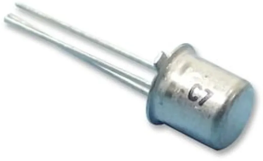
The BC107 is a low-power, NPN bipolar junction transistor (BJT) primarily utilized for switching and amplification purposes in electronic circuits. Characterized by its ability to control current flow between its collector and emitter terminals based on the current applied to its base terminal, it functions as a fundamental building block in numerous analog and digital electronic designs.
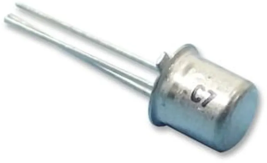
The BC107 is a low-power NPN bipolar junction transistor characterized by specific electrical parameters that dictate its performance in various electronic circuits. Understanding these key specifications is critical for effective circuit design and troubleshooting. The most important parameters include voltage ratings, current handling capability, power dissipation, and frequency response.
| Parameter | Symbol | Value | Unit | Description |
|---|---|---|---|---|
| Collector-Emitter Voltage | Vceo | 45 | V | Maximum voltage that can be applied between the collector and emitter with the base open. |
| Collector-Base Voltage | Vcbo | 50 | V | Maximum voltage that can be applied between the collector and base with the emitter open. |
| Emitter-Base Voltage | Vebo | 5 | V | Maximum voltage that can be applied between the emitter and base with the collector open. |
| Continuous Collector Current | Ic | 200 | mA | Maximum continuous current that can flow through the collector. |
| Power Dissipation | Pd | 600 | mW | Maximum power that the transistor can safely dissipate as heat. |
| Transition Frequency | fT | 150 | MHz | Frequency at which the current gain of the transistor drops to unity. |
These parameters provide a fundamental understanding of the BC107's operational limits. It is important to operate the transistor within these limits to ensure reliable performance and prevent damage. Datasheets provide a comprehensive list of parameters and characteristics under different conditions.
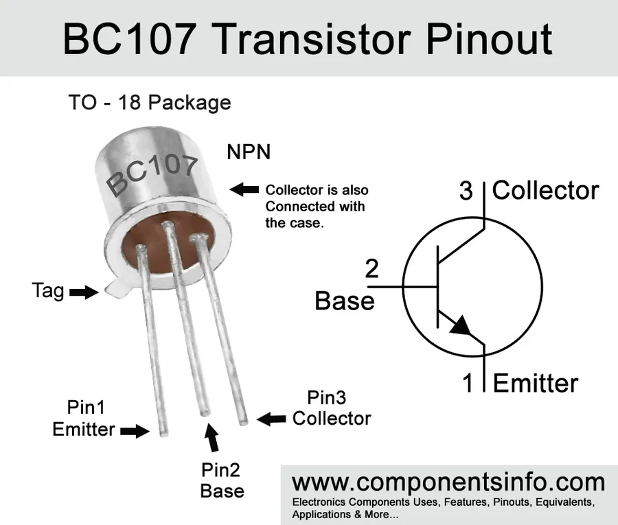
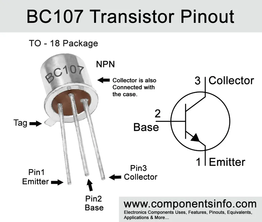
The BC107 transistor is housed in a TO-18 metal can package, a common configuration for small signal transistors. Understanding its pinout—the arrangement of its base, collector, and emitter terminals—is critical for proper circuit integration and operation. Incorrect pin connections can lead to circuit malfunction or damage to the transistor.
| Pin Number | Pin Name | Description |
|---|---|---|
| 1 | Emitter | The terminal through which current flows out of the transistor. It is often connected to ground or a lower potential. |
| 2 | Base | The control terminal that modulates the current flow between the collector and the emitter. A small current into the base will control a larger current flow through the transistor. |
| 3 | Collector | The terminal through which current flows into the transistor. It is often connected to the load or a higher potential. |
The TO-18 package is characterized by its three leads emanating from the bottom of the metal can. Viewed from the bottom with the leads pointing towards you, the pins are arranged in a triangle, where the leads are numbered counterclockwise. Pin 1 is the emitter, Pin 2 is the base, and pin 3 is the collector.
When integrating the BC107 into a circuit, it’s important to observe the polarity. The base must be correctly biased to achieve transistor operation, and the orientation of the collector and emitter terminals will determine the current flow direction. For NPN transistors like the BC107, the collector is at a higher potential than the emitter during normal operation, with current flowing from collector to emitter when the transistor is active.
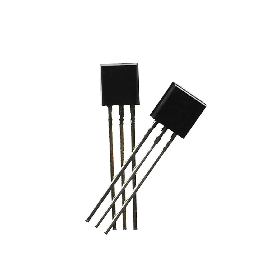
The BC107 and BC107B are both NPN bipolar junction transistors (BJTs) housed in the TO-18 metal can package, however, they are not identical. The primary distinction lies in their gain characteristics, specifically the current gain (hFE), which translates to differences in their amplification capability and application suitability. While both are low-power devices, the 'B' variant is typically selected for applications requiring tighter gain control.
| Parameter | BC107 | BC107B |
|---|---|---|
| Current Gain (hFE) | Generally lower, specified range (e.g., 110-220) | Generally higher, tighter range (e.g., 200-450) |
| Typical Application | General-purpose amplification, less critical gain | Amplification or switching applications requiring tighter gain specifications |
| Voltage Ratings (Vceo, Vcbo, Vebo) | Identical (e.g., Vceo=45V) | Identical (e.g., Vceo=45V) |
| Current Rating (Ic) | Identical (e.g., Ic=200mA) | Identical (e.g., Ic=200mA) |
| Power Dissipation | Identical (e.g., 600mW) | Identical (e.g., 600mW) |
The use of the 'B' suffix typically indicates that the device has undergone specific binning or sorting to achieve a more precise range of hFE values. This is crucial in applications where consistent performance across multiple devices or production runs is required. While the absolute maximum ratings (voltage, current, power) for both variants are usually identical, the selection should primarily be driven by the amplification requirements of the circuit.
The BC107 transistor, a versatile NPN bipolar junction transistor (BJT), finds its utility in a range of electronic circuits, primarily where low power and moderate amplification are required. Its characteristics make it suitable for applications such as driver stages, audio preamplifiers, and various low-power switching applications. The BC107's design allows for efficient signal processing and control in these contexts.
The BC107, while a reliable NPN transistor, may not always be readily available or optimal for every design. Identifying suitable equivalents and substitutes is crucial for maintaining design flexibility and ensuring supply chain continuity. This section details commonly used replacements, focusing on their similarities and differences with the BC107, particularly concerning pinout configurations and circuit adjustments.
| Transistor | Type | Vceo (Max) | Ic (Max) | Package | Key Considerations |
|---|---|---|---|---|---|
| BC107 | NPN | 45V | 200mA | TO-18 | Standard low-power NPN |
| BC547 | NPN | 45V | 100mA | TO-92 | Commonly available, lower current |
| 2N3904 | NPN | 40V | 200mA | TO-92 | General-purpose, good substitute |
| 2N2222 | NPN | 30V | 800mA | TO-18/TO-92 | Higher current capabilities |
| BC108 | NPN | 20V | 200mA | TO-18 | Similar but lower voltage rating |
When considering replacements for the BC107, it is essential to evaluate the critical parameters and compare them against your application requirements. The BC547 is a very common substitute. It has similar voltage ratings but typically has a lower current carrying capacity than the BC107. The 2N3904 is another viable option with good general purpose characteristics and is widely available, though typically in a TO-92 package, which may require circuit board modifications to replace the BC107 which typically comes in a TO-18. The 2N2222 also a strong contender, with a higher current rating than the BC107. A less common choice, the BC108 is very similar to the BC107 but has lower voltage specifications.
This section addresses common questions regarding the BC107 transistor, clarifying its nomenclature, suitable replacements, and typical applications. Understanding these aspects is crucial for effectively utilizing the BC107 in electronic circuits.
Handling BC107 transistors requires careful attention to prevent damage and ensure reliable circuit operation. The TO-18 metal can package, while robust, has specific limitations that must be understood for effective use. Proper soldering techniques, thermal management, and troubleshooting strategies are essential for successful implementation of the BC107 in electronic designs.
A thorough understanding of the BC107 datasheet is paramount for its effective utilization in electronic circuits. This section provides guidance on interpreting critical parameters and curves within the datasheet to ensure optimal performance and reliability.
| Parameter | Symbol | Typical Value | Unit | Notes |
|---|---|---|---|---|
| Collector-Emitter Voltage | VCEO | 45 | V | Maximum limit |
| Collector Current | IC | 200 | mA | Maximum limit |
| Total Power Dissipation | PD | 600 | mW | at 25°C |
| DC Current Gain | hFE | 120-800 | - | Range at specific conditions |
| Operating Temperature | Tj | -65 to +150 | °C | Range |
The BC107 transistor, a small NPN bipolar transistor, has played a key role in the history of electronics due to its reliability and versatility. By understanding its specifications, pinout, applications, and equivalent options, electronics enthusiasts and engineers can leverage the bc107 transistor and similar components effectively in their projects, understanding its continued relevance in both educational and practical contexts. The provided information should empower you to effectively utilize this device in your electronic ventures, whether for repair, experimentation, or new designs.

