Understanding the Role and Applications of pF Capacitors
2025.02.04
Have you ever wondered how those tiny components on a circuit board store electrical energy? One of the key players is the capacitor, and among them, the picofarad (pF) capacitor stands out for its ability to manage incredibly small amounts of charge. In this article, we will delve into the significance of pF capacitors, explore their role in electronics, and uncover the magic behind their conversion and applications, bridging the gap between science and the tech that surrounds us daily.
What is a Picofarad (pF) Capacitor?
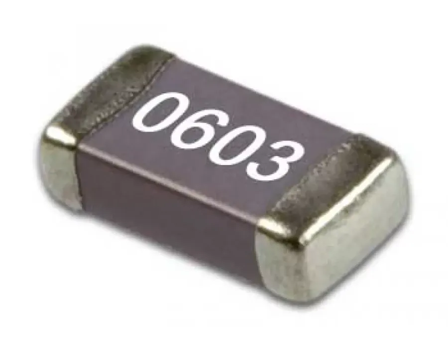
SMD Ceramic Capacitors
A picofarad (pF) is a unit of capacitance, representing one trillionth (10⁻¹²) of a farad. It's a fundamental unit used to measure a capacitor's ability to store an electrical charge. In practical terms, pF capacitors are extremely small in capacitance compared to other common units, like microfarads (µF) or nanofarads (nF), with 1 µF being equal to 1,000,000 pF and 1 nF being equal to 1,000 pF. The core function of any capacitor, including those measured in picofarads, is to accumulate electrical energy by storing opposite charges on its conductive plates, separated by a dielectric material.
pF Capacitor Values and Their Significance
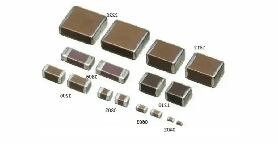
SMD Capacitors Various Sizes
Picofarad (pF) capacitors, while representing very small capacitance values, are crucial components in electronic circuits, particularly where high-frequency performance is paramount. Their values, typically ranging from single-digit pF to a few thousand pF, are carefully selected based on specific circuit requirements, influencing performance in applications such as impedance matching and high-frequency filtering.
Capacitance Value (pF)
Typical Application
Significance
1 pF to 10 pF
High-frequency tuning circuits, RF matching
Used in circuits requiring very precise capacitance, e.g., resonant circuits or impedance matching for RF signals, where a subtle change in capacitance can significantly affect performance. Often used as trimmers to fine-tune circuit parameters.
10 pF to 100 pF
Filtering, Oscillators
Essential for filtering out noise and unwanted frequencies, and for establishing resonant frequencies in oscillators. These values help in setting the cut-off frequency of a filter or the operating frequency of an oscillator circuit, with applications in RF receivers and transmitters.
100 pF to 1000 pF
Bypass capacitors, Decoupling
Used in decoupling applications to filter high-frequency noise from power lines. The goal here is to provide a local source of charge to transient loads. These values provide excellent high frequency behavior, but can be less effective in lower frequency regimes, thus are often used in conjunction with larger capacitors
1000 pF and above
Timing circuits, General purpose coupling
Used in timing circuits where they set the duration of events, and used for general coupling of signals. While they can be used in filtering applications, they tend to be used in areas where moderate to high capacitance is required, but high frequency behavior is still desired.
Capacitance Conversion: pF to µF, nF, and Beyond
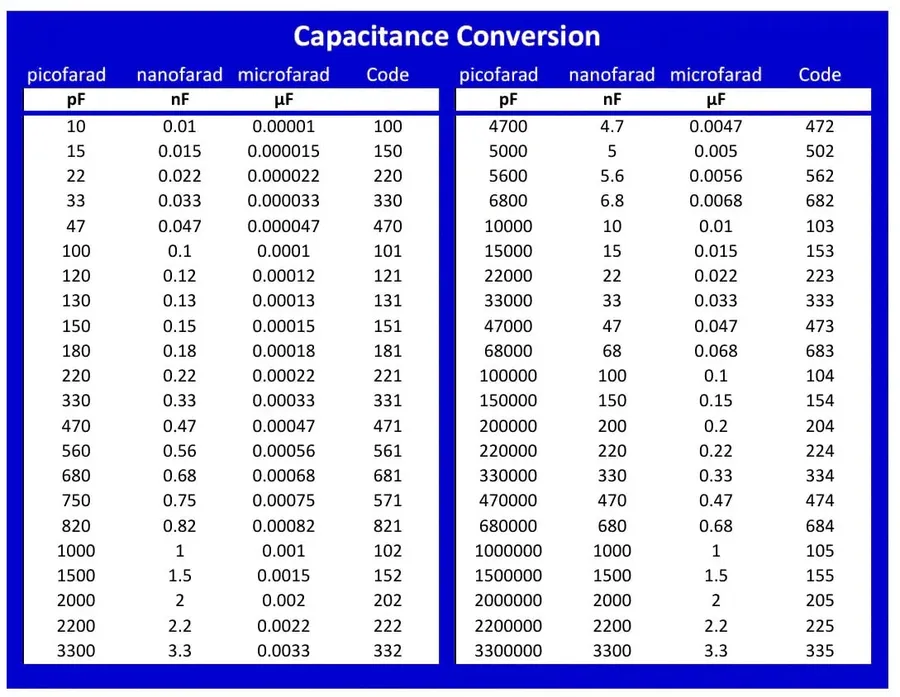
Capacitance Unit Conversion Table
Accurate capacitance conversion between picofarads (pF), microfarads (µF), nanofarads (nF), and farads (F) is crucial for selecting the correct capacitor for a given application. These conversions are based on powers of ten, where understanding the relationships between units is essential for circuit design and analysis.
Conversion
Formula
Example
pF to nF
Value (nF) = Value (pF) / 1000
1000 pF = 1 nF
pF to µF
Value (µF) = Value (pF) / 1,000,000
1,000,000 pF = 1 µF
pF to F
Value (F) = Value (pF) / 1,000,000,000,000
1,000,000,000,000 pF = 1 F
nF to pF
Value (pF) = Value (nF) * 1000
1 nF = 1000 pF
nF to µF
Value (µF) = Value (nF) / 1000
1000 nF = 1 µF
nF to F
Value (F) = Value (nF) / 1,000,000,000
1,000,000,000 nF = 1 F
µF to pF
Value (pF) = Value (µF) * 1,000,000
1 µF = 1,000,000 pF
µF to nF
Value (nF) = Value (µF) * 1000
1 µF = 1000 nF
µF to F
Value (F) = Value (µF) / 1,000,000
1,000,000 µF = 1 F
The importance of proper conversions lies in ensuring that the capacitor's capacitance is within the desired range for the circuit. For example, using a capacitor that is a few orders of magnitude too high or low in capacitance can lead to circuit malfunction, instability or damage. Therefore, meticulous conversion and accurate calculations are essential steps in any electronics design process.
Applications of pF Capacitors in Electronics
RF Circuit with Capacitors
Picofarad (pF) capacitors, while seemingly small in capacitance, play crucial roles in numerous electronic applications, particularly where high frequencies or precise timing are involved. Their ability to quickly charge and discharge makes them essential components in circuits that handle rapid signal changes, operating within radio frequencies, filtering high frequencies, and facilitating signal timing.
Radio Frequency (RF) Circuits In RF circuits, pF capacitors are used for tuning, impedance matching, and filtering. They help in selecting specific frequencies by resonating with inductors, crucial in radio receivers and transmitters. Their low capacitance allows for fine-tuning in high-frequency applications where even small parasitic capacitance could cause detuning. Specifically, they are deployed in impedance matching networks to maximize power transfer and minimize signal reflections in antennas and transmission lines.
Filters pF capacitors are fundamental to filter design, particularly in high-frequency filters, such as low-pass, high-pass, and band-pass filters. In low-pass filters, they effectively shunt high-frequency noise to the ground, while in high-pass filters, they block low-frequency signals. The precision offered by pF capacitors enables the creation of filters with specific cutoff frequencies crucial for signal conditioning and noise reduction in sensitive electronic equipment. The selection of a pF capacitor is vital to establishing a precise cut-off frequency for filtering.
Oscillators In oscillator circuits, pF capacitors are critical for establishing the frequency of oscillation. The oscillation frequency is often determined by the interaction between a capacitor and an inductor or a crystal. Their stability and accuracy are paramount in timing circuits and frequency generation used in microprocessors and other timing-sensitive applications. The precision of pF capacitors contributes to the overall stability of the oscillator.
High-Speed Data Lines In high-speed digital circuits, pF capacitors are used to maintain signal integrity by acting as a bypass. They also assist with decoupling of the power supply lines by shunting high-frequency noise, reducing signal reflection, and ensuring the proper operation of high-speed components. Their low capacitance value prevents signal distortion by quickly accommodating rapid current changes. For instance, pF capacitors are commonly placed near the power pins of digital integrated circuits to prevent transient voltage drops.
Impedance Matching In impedance matching circuits, pF capacitors can help to match the impedance of different parts of a circuit, which is important for maximizing power transfer and minimizing signal reflection. For example, pF capacitors might be used in an impedance matching network between an amplifier and an antenna.
Why Do We Use pF Capacitors in Parallel with Other Capacitors?
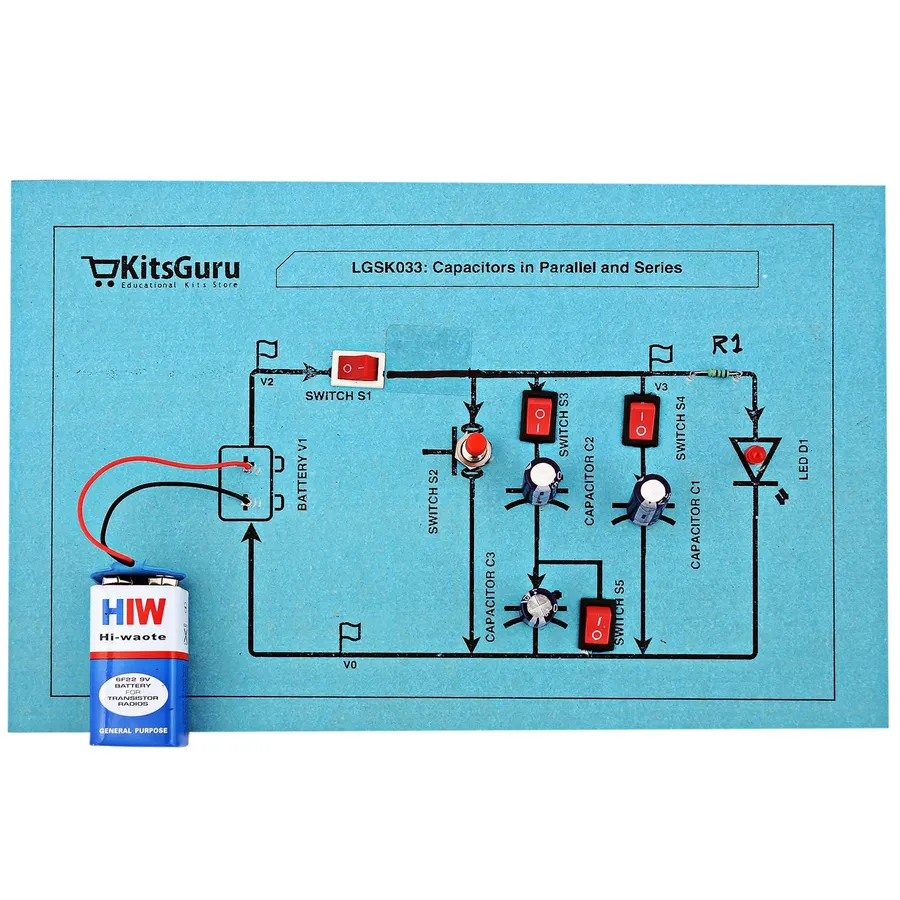
Parallel Capacitors Circuit
Picofarad (pF) capacitors are frequently employed in parallel with larger capacitance units, such as microfarad (µF) capacitors, to optimize circuit performance, particularly in power supply filtering and high-frequency applications. This parallel configuration addresses limitations that each capacitor type exhibits when used in isolation.
Enhanced Power Supply Filtering Larger capacitors, like µF capacitors, are effective at smoothing out low-frequency noise and voltage ripples in power supplies. However, they are less effective at high frequencies due to their inherent parasitic inductance. Adding a smaller pF capacitor in parallel provides a low impedance path for these high-frequency components, improving the overall filtering performance. The pF capacitor acts as a bypass capacitor, shunting high-frequency noise to ground, while the larger capacitor handles the bulk energy storage.
Mitigating Impedance at Higher Frequencies At high frequencies, the impedance of a capacitor is not purely capacitive; parasitic inductance and resistance within the capacitor itself become significant, increasing its impedance and reducing its effectiveness. The self-resonant frequency of a capacitor is where the impedance is at a minimum, and at higher frequencies than the self-resonant frequency, the capacitor actually starts to act like an inductor due to the parasitic inductance. Smaller pF capacitors have lower parasitic inductance and thus are more effective at providing low impedance paths for higher frequencies. By placing a pF capacitor in parallel with larger capacitors, we mitigate impedance effects at high frequencies by providing a path for current to flow at those frequencies through the pF capacitor, making the effective impedance of the parallel combination lower than what would be achieved with either capacitor alone at high frequencies.
Optimized Frequency Response The combined parallel capacitance provides a wider range of effective impedance across a broad frequency spectrum. The larger capacitor provides good performance at low frequencies, and the pF capacitor provides better performance at high frequencies, thereby broadening the effective frequency range for the combined parallel capacitor network.
Factors Affecting pF Capacitor Selection
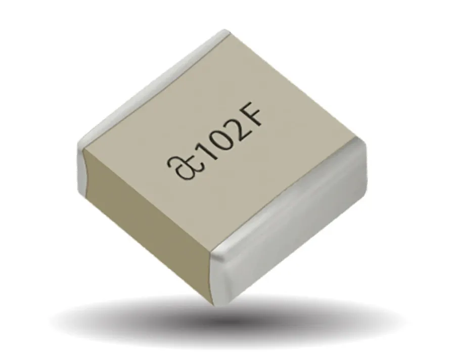
High Precision Capacitor
Selecting the appropriate pF capacitor requires careful consideration of several key factors to ensure optimal circuit performance and reliability. These factors include tolerance, temperature coefficient, and voltage rating, each playing a critical role in how the capacitor behaves within a circuit.
Factor
Description
Impact on Performance
Tolerance
The permissible deviation of the actual capacitance value from its stated nominal value, often expressed as a percentage.
A tighter tolerance ensures that the capacitor's value is closer to the intended design value. Loose tolerance can affect circuit tuning, impedance matching, and filter performance.
Temperature Coefficient
Measures the change in capacitance per degree Celsius. It is often specified in parts per million per degree Celsius (ppm/°C).
A stable temperature coefficient is critical in environments with varying temperatures. Changes in capacitance due to temperature fluctuations can lead to performance drift in oscillators, filters, and timing circuits.
Voltage Rating
The maximum voltage that the capacitor can safely withstand without the risk of dielectric breakdown or damage. It is often specified as a DC voltage.
Operating a capacitor above its rated voltage can lead to dielectric failure, resulting in a short circuit or component degradation. Selecting an appropriate voltage rating is necessary for reliability and safety.
Frequently Asked Questions About pF Capacitors
This section addresses common questions about picofarad (pF) capacitors, providing clear and concise answers to enhance understanding of their characteristics, usage, and conversions.
What exactly is a picofarad (pF) in a capacitor? A picofarad (pF) is a unit of capacitance, representing one trillionth (10^-12) of a farad. It quantifies a capacitor's ability to store an electrical charge. Specifically, a 1 pF capacitor stores 1 picocoulomb of charge when a voltage of 1 volt is applied across its terminals.
What is the relationship between pF and other capacitance units, such as uF and nF? Capacitance units are related by powers of 1000. 1 microfarad (µF) equals 1,000,000 picofarads (pF). Similarly, 1 nanofarad (nF) equals 1,000 pF. Thus, a larger unit like the microfarad (µF) represents a greater charge storage capacity compared to the nanofarad or picofarad.
What is 1000 pF equal to in terms of other capacitance units? 1000 pF is equivalent to 1 nanofarad (nF). This conversion is crucial in circuit design because different applications may call for capacitance values expressed in different units. Understanding the equivalency allows for easy substitution when components with varying unit labels are used.
How do you calculate the value of a pF capacitor? The value of a capacitor, including pF capacitors, is typically determined during manufacturing and is printed on the component's package or can be identified through its color code. While you can calculate the theoretical capacitance based on physical dimensions and dielectric properties through the parallel plate capacitor formula (C = εA/d), practically, these calculations are complex for commercial capacitors due to multilayered structure. For practical purposes, reading the markings on the device itself is the best method.
How can I convert picofarads (pF) to microfarads (µF)? To convert from picofarads (pF) to microfarads (µF), divide the pF value by 1,000,000 (10^6). The conversion formula is: µF = pF / 1,000,000. For example, 1,000,000 pF equals 1 µF. This conversion is essential when working with circuits that use capacitors with different units and allows engineers to make practical and effective substitutions.
Why are pF capacitors so important in high-frequency circuits? pF capacitors are critical in high-frequency circuits due to their low capacitance and minimal impedance, which make them ideal for filtering out unwanted high-frequency signals while allowing lower frequencies to pass through. They exhibit low parasitic inductance and resistance, allowing for high accuracy and very precise impedance control in circuits for RF applications such as impedance matching and tuning.
Can pF capacitors be used in power supply circuits? While larger capacitors (µF range) are the mainstays of power supply filtering, pF capacitors play a crucial role when used in parallel with larger capacitors in power supply circuits. pF capacitors help suppress high-frequency noise and reduce the overall impedance of the circuit, which ensures that unwanted high frequency noise components are filtered out while allowing for efficient power delivery by the main capacitors. This is vital for a stable and reliable power output.
Practical Tips for Working with pF Capacitors
Handling pF capacitors requires care and precision due to their small size and sensitivity. Proper techniques during soldering and installation are crucial for maintaining their performance and longevity. Engineers and hobbyists should adhere to specific guidelines to avoid damaging these components and ensure the reliability of the circuits they are used in.
Handling Precautions Always handle pF capacitors by their body, avoiding direct contact with the leads, as static discharge can damage them. Use ESD-safe tools and grounding techniques while handling these components to prevent static-related failures.
Soldering Techniques Use a fine-tipped soldering iron and precise temperature control when soldering pF capacitors. Excessive heat can alter their characteristics or cause physical damage, affecting their intended performance. It is essential to minimize the soldering time to reduce the thermal stress on the capacitor.
Lead Forming When lead forming is required for through-hole pF capacitors, use appropriate lead forming tools to avoid applying excessive mechanical stress. Excessive bending can damage internal connections within the component, leading to malfunction or failure.
Proper Storage Store pF capacitors in a dry, low-humidity environment, away from temperature extremes. High humidity or temperature can accelerate the degradation of the capacitor's dielectric material over time, which may affect its performance and shelf life.
Inspection Before Use Before incorporating a pF capacitor into a circuit, conduct a visual inspection for any signs of damage, such as cracks, fractures, or deformed leads. Damaged capacitors can lead to unpredictable performance or circuit failure.
Component Orientation Be aware of the polarity of polarized capacitors. Although most pF capacitors are non-polarized, verify before installation. Incorrect orientation can cause damage or malfunction. When working with polarized capacitors in the pF range, ensure proper orientation as reversing the polarity can cause damage to the capacitor and the circuit.
Using the correct solder Use appropriate solder with the correct composition for pF capacitors. Inappropriate solder types can introduce unwanted resistance or other issues. Always use solder that is appropriate for the type of components and the intended application.
Troubleshooting and Common Issues with pF Capacitors
Picofarad (pF) capacitors, while small in capacitance, are crucial in high-frequency circuits, but they are not immune to issues. Understanding common problems and how to troubleshoot them ensures optimal circuit performance and reliability. This section will cover performance drift, failure modes, and provide effective troubleshooting strategies.
Performance Drift Capacitance values can drift over time due to factors like temperature changes, aging, or exposure to harsh environments, resulting in deviations from the expected circuit behavior. Regular monitoring and replacement of these components might be necessary, especially in precision circuits.
Failure Modes Common failure modes include open circuits, short circuits, and parametric failures where the capacitor still functions, but is outside the tolerance specifications. Open circuits typically manifest as a complete lack of capacitance, while short circuits can cause damage to the circuit.
Soldering Damage Excessive heat during soldering can damage pF capacitors, particularly smaller surface-mount devices (SMD), potentially altering their capacitance or causing a complete failure. Always use appropriate soldering techniques and tools and minimize heat exposure.
Physical Damage Cracks or other mechanical damage can alter a capacitor’s capacitance or lead to failure. Handle the capacitors carefully and inspect them for damage before installation.
Moisture Ingress Exposure to excessive moisture can degrade the insulation within the capacitor, increasing leakage current and affecting its performance. Use proper storage and handling methods, especially in humid environments, to avoid this issue.
Below is a guide to assist in troubleshooting common issues:
Visual Inspection Carefully examine the capacitor for signs of physical damage, such as cracks, bulging, or discoloration. This can be an early indicator of potential issues.
Capacitance Measurement Use an LCR meter to accurately measure the capacitor's capacitance and compare it with the specified value. Significant deviations can indicate a failure or performance drift.
Temperature Checks If the capacitor is operating in high-frequency applications, use thermal imaging or a multimeter with a temperature probe to ensure it's operating within its specified thermal range to avoid damage or performance fluctuations.
Circuit Performance Analysis Analyze the circuit's overall behavior, noting any performance anomalies that might be linked to the capacitor. These issues can include oscillations, noise, or impedance mismatch problems.
Replace if Necessary If any of the checks above indicate a problem, replace the suspect capacitor with a new one. In particular, replace devices that are significantly out of tolerance or demonstrate any signs of failure.
In conclusion, the humble pF capacitor plays an indispensable role in the world of electronics. Its ability to handle minute charges makes it critical in everything from RF circuits to high-speed data lines. Understanding how to select, convert, and troubleshoot pF capacitors is essential for anyone working with electronics. As technology continues to advance, the importance of these small yet powerful components will only continue to grow. It can even impact things we do in daily life, for example, the smoothness of a phone call or the stability of a wireless internet connection, and the selection of the right pF capacitor helps us improve our quality of life.