In the world of electronics, controlling high-power devices is essential. Imagine the seemingly simple task of dimming a light or driving a motor—this is where the TIP120 Darlington transistor shines. This powerful component acts as a digital switch, allowing microcontrollers like Arduino to manage substantial current loads. From industrial machinery to hobbyist projects, the TIP120 makes it possible to bridge the gap between digital control and real-world power. This article will delve into the inner workings of the TIP120, exploring its applications, limitations, and best practices for implementation.
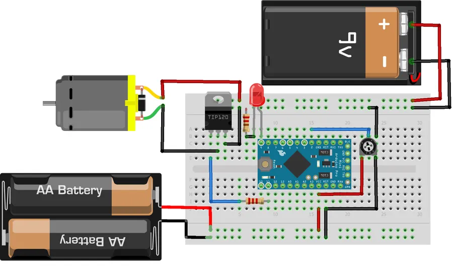
The TIP120 is an NPN Darlington transistor, a configuration that provides significantly higher current gain than a standard bipolar junction transistor (BJT). This makes it suitable for applications where a small control current needs to switch a larger load. Unlike a single BJT, the Darlington configuration uses two BJTs cascaded together, multiplying the current gain of each to achieve an overall higher gain.
At its core, the TIP120 combines two BJTs where the emitter of the first transistor drives the base of the second. This arrangement allows for a much larger current to flow through the collector-emitter path for a given base current, making it a very efficient switch for driving high current loads from low-power control signals. This device is commonly used to switch power to motors, solenoids, and other high-current devices controlled by low-power electronics.
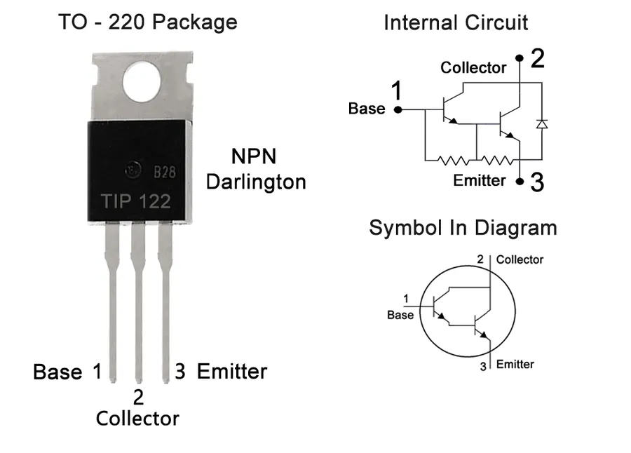
The TIP120 is a three-terminal NPN Darlington transistor, and understanding its pin configuration is crucial for proper circuit design and operation. Each pin—base, collector, and emitter—plays a distinct role in the transistor's function as a current amplifier and switch.
| Pin | Symbol | Description | Function |
|---|---|---|---|
| Base | B | Input control pin. | The base terminal is used to control the flow of current between the collector and emitter. A small current applied to the base terminal will allow a larger current to flow from the collector to emitter. |
| Collector | C | Output current carrying pin. | The collector terminal is connected to the high voltage part of the circuit and where the amplified current flow exists when the transistor is switched on. |
| Emitter | E | The reference point for current. | The emitter terminal is connected to the low voltage part of the circuit, and usually connected to the negative terminal or ground of the power supply. |
Understanding the TIP120's operational limits is crucial for reliable circuit design. This section details the key specifications and performance parameters, including voltage and current ratings, gain, and power dissipation, as well as its peak current handling capabilities. These parameters directly influence how the transistor can be used effectively.
| Parameter | Value | Description |
|---|---|---|
| Collector-Emitter Voltage (VCEO) | 60V | Maximum voltage the transistor can withstand between collector and emitter when the base is open. |
| Collector Current (IC) Continuous | 5A | Maximum continuous current that can flow through the collector. |
| Collector Current (IC) Peak | 8A | Maximum peak current the transistor can handle for short durations. |
| Base Current (IB) | 120mA | Maximum base current for proper operation. |
| DC Current Gain (hFE) | 1000 (typical) | The ratio of collector current to base current; indicates the amplification factor. |
| Power Dissipation (PD) | 65W | Maximum power the transistor can dissipate as heat under specified conditions (typically when mounted on a heatsink). |
| Operating Temperature Range | -65°C to +150°C | Temperature range within which the transistor is designed to operate reliably. |
The TIP120's Darlington configuration contributes to its high current gain (hFE). This means a small base current can control a much larger collector current, making it suitable for switching applications. However, the internal structure also means there is a higher saturation voltage than standard BJT, and a higher voltage drop when active, which are important considerations in circuit design. Proper thermal management, often using a heatsink, is critical to prevent overheating and damage, especially when operating near the maximum power dissipation.
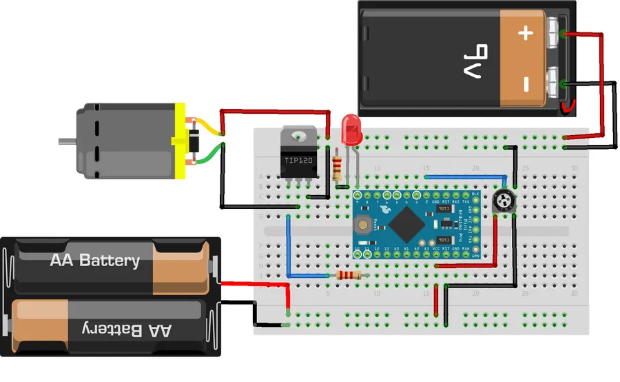
The TIP120 Darlington transistor, owing to its high current gain and ability to handle substantial loads, finds extensive use in practical applications where microcontrollers alone are insufficient. It acts as a robust switch, enabling control of high-power devices from low-power control signals. This section will explore its applications in controlling motors, solenoids, and high-brightness LEDs, providing example circuits and design considerations.
In each of these applications, the base of the TIP120 is connected to the control signal from the microcontroller, typically through a current-limiting resistor. The load is connected between the collector and the positive supply, with the emitter connected to ground. Furthermore, a flyback diode is often connected across the inductive load (e.g., motors, solenoids) to protect the transistor from voltage spikes that can occur during switching. Proper component selection and heat management are important for stable operation, which is expanded upon in the section 'Limitations and Considerations when Using a TIP120'.
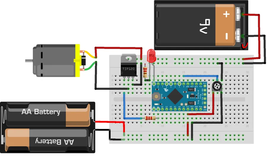
The TIP120 Darlington transistor, when paired with an Arduino microcontroller, provides a robust solution for controlling DC motors. This configuration allows the low current output of the Arduino to efficiently switch the higher currents required by many DC motors. The key to safe and reliable operation involves understanding the circuit requirements and incorporating a flyback diode for protection.
While the TIP120 Darlington transistor is a versatile component for switching applications, it's essential to understand its limitations to ensure optimal circuit design and performance. Key factors to consider include its relatively slow switching speed, inherent current leakage, and voltage drop characteristics, particularly when handling substantial power loads.

The choice between a TIP120 Darlington transistor and a MOSFET (Metal-Oxide-Semiconductor Field-Effect Transistor) hinges on specific application requirements, particularly concerning switching speed, efficiency, and load characteristics. While both are used for switching and amplification, their fundamental differences dictate their optimal use cases.
| Feature | TIP120 Darlington Transistor | MOSFET |
|---|---|---|
| Switching Speed | Relatively slow (kHz range) | Very fast (MHz range) |
| Efficiency | Lower due to base current requirement and voltage drop | Higher, very low gate current and low on-resistance |
| Voltage Drop (VCEsat) | Significant voltage drop across collector-emitter junction (VCEsat around 2V) | Very low voltage drop, determined by on-resistance (RDS(on)) |
| Gate Drive Requirement | Requires significant base current for saturation | Voltage-driven, very low gate current |
| Heat Dissipation | Higher heat generation due to internal losses, requires a heat sink for medium and high power applications | Lower heat generation for the same load, heat sink may not be necessary in some low power applications. |
| Cost | Generally lower cost | Can be more expensive, especially for high power applications |
| Typical Applications | DC motor control, low-frequency switching, moderate current applications | High frequency switching, power supplies, highly efficient motor control |
| Complexity | Simpler to implement in basic circuits | Can require more complex gate driver circuitry |
In summary, for applications demanding fast switching speeds and high efficiency, such as switched-mode power supplies or high-frequency motor control, MOSFETs are generally the superior choice. Conversely, for cost-sensitive applications with lower frequency switching needs or where simplicity of implementation is preferred, the TIP120 provides a robust, albeit less efficient, solution.
This section addresses common questions about the TIP120 Darlington transistor, providing concise answers to help clarify its functionality, specifications, and application.
The TIP120 Darlington transistor is a workhorse in electronics, enabling seamless control of high-power loads from low-power control circuits. Understanding its capabilities and limitations is key to designing efficient and robust circuits. Whether you're powering a motor for a robotics project or controlling high-intensity LEDs, the TIP120 serves as a valuable tool. This guide, which covers everything from pinouts to practical examples, equips you with the knowledge to leverage the power of the TIP120 effectively, helping you switch high-power electronics safely and reliably. While it has its limitations, particularly compared to MOSFETs, it remains a practical and cost-effective solution for many projects.

