From tuning your old radio to modern wireless communication, the variable capacitor plays a key role in manipulating capacitance, a fundamental aspect of electronics. This seemingly simple component has enabled countless technological advances, impacting both our day-to-day lives and leading-edge technologies. This article will demystify the variable capacitor, exploring its various types, applications, and selection criteria, enabling you to confidently utilize them in your projects.
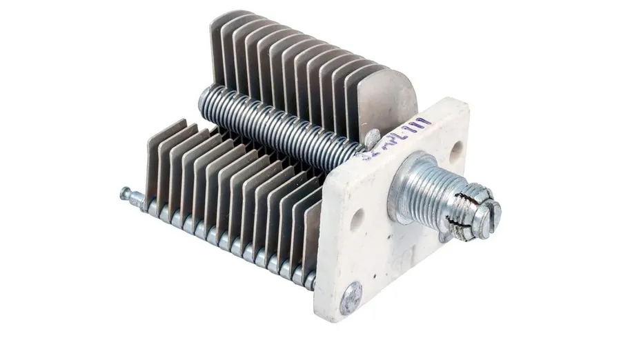
A variable capacitor is an electrical component whose capacitance can be intentionally and repeatedly changed, unlike a fixed capacitor which has a set capacitance value. This adjustability, achieved through mechanical or electronic means, allows variable capacitors to play crucial roles in tuning circuits, impedance matching, and various other electronic applications. The core principle relies on altering the effective area, spacing, or dielectric material between the conductive plates of the capacitor.
The core elements of a variable capacitor typically include two or more conductive plates, often made from metal, and a dielectric material positioned between these plates. The capacitance, determined by the formula C = εA/d (where ε is the permittivity of the dielectric, A is the overlapping area of the plates, and d is the distance between the plates), can be altered by changing any of these parameters.
Common materials for the plates include aluminum, brass, and silver plated metal. For dielectric materials, air, ceramics, and polymers are frequently used, each offering different performance characteristics and temperature coefficients. Air variable capacitors utilize air as the dielectric, while ceramic trimmers and varactors, rely on ceramics and semiconductor junctions, respectively, for their capacitance adjustments.
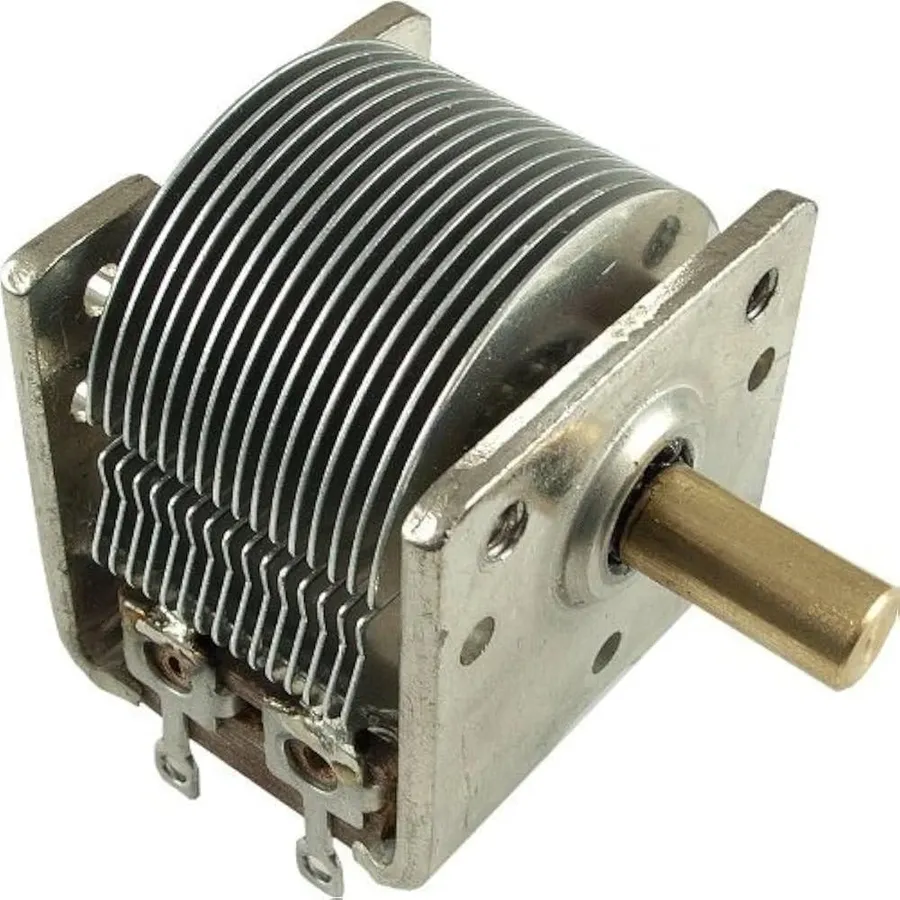
Variable capacitors, crucial components in adjustable circuits, come in several types, each with unique construction, capacitance ranges, and applications. The most prevalent include air variable capacitors, ceramic trimmer capacitors, and varactor diodes, each designed to fulfill distinct needs in electronic designs. This section details the core attributes, strengths, and weaknesses of each type.
| Type | Construction | Capacitance Range | Typical Applications | Advantages | Disadvantages |
|---|---|---|---|---|---|
| Air Variable Capacitor | Moving metal plates separated by air gap. | 10 pF to 500 pF | Tuning circuits, high-frequency RF applications. | High Q factor, low loss. | Large size, sensitive to mechanical vibration, susceptible to environmental factors. |
| Ceramic Trimmer Capacitor | Ceramic dielectric with adjustable screw mechanism. | 1 pF to 30 pF | Fine-tuning circuits, compact applications. | Small size, precision adjustment. | Lower Q factor, limited capacitance range, temperature sensitivity. |
| Varactor Diode | Semiconductor diode with reverse-bias controlled capacitance. | Few pF to 100s of pF | Electronic tuning, voltage-controlled oscillators. | Electronic control, fast response. | Non-linearity, temperature sensitivity, lower Q. |
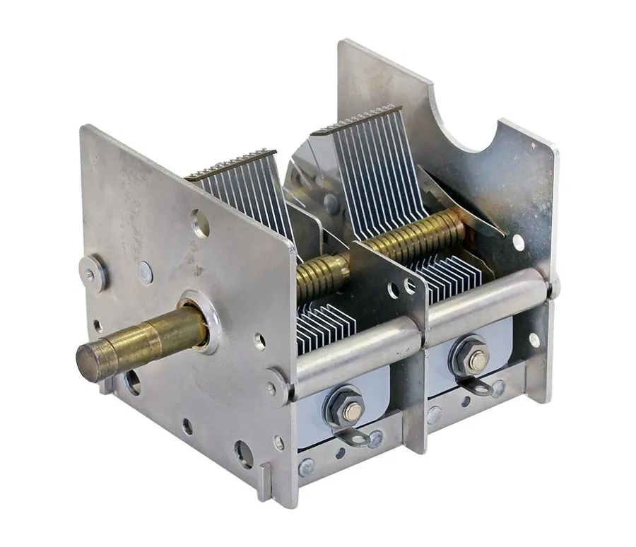
Air variable capacitors are a type of adjustable capacitor distinguished by their use of air as the dielectric material between their conductive plates. This design facilitates precise capacitance tuning, primarily through mechanical adjustments that alter the overlapping area of the plates, making them particularly useful in applications requiring high precision and stability.
The construction of an air variable capacitor centers on two sets of conductive plates: a stationary set (stator) and a rotating set (rotor). The rotor plates are attached to a shaft, allowing for manual adjustment of the overlapping area between the stator and rotor plates. As the plates overlap more or less, the effective capacitance of the device changes, following the fundamental capacitance equation: C = ε(A/d), where 'C' is capacitance, 'ε' is the dielectric constant (permittivity of air), 'A' is the overlapping area of the plates, and 'd' is the separation between the plates. In air variable capacitors, 'A' is the primary variable adjusted to change capacitance. The air dielectric leads to very low loss.
Air variable capacitors are particularly well-suited for tuning circuits in radio frequency (RF) applications. Their low dielectric losses and high Q factor—a measure of the energy storage versus energy loss—make them ideal for applications like resonant circuits in radio transmitters and receivers where minimal energy dissipation is crucial for optimal performance.
| Parameter | Description | Typical Values |
|---|---|---|
| Dielectric Material | Material separating the plates. | Air |
| Capacitance Range | Typical adjustable range of capacitance. | 10 pF to 500 pF (can vary) |
| Q Factor | Measure of energy storage efficiency. | High (typically >1000) |
| Adjustment Mechanism | Method for changing capacitance. | Mechanical, via rotating plates |
| Applications | Common use cases. | Radio tuning circuits, RF applications |
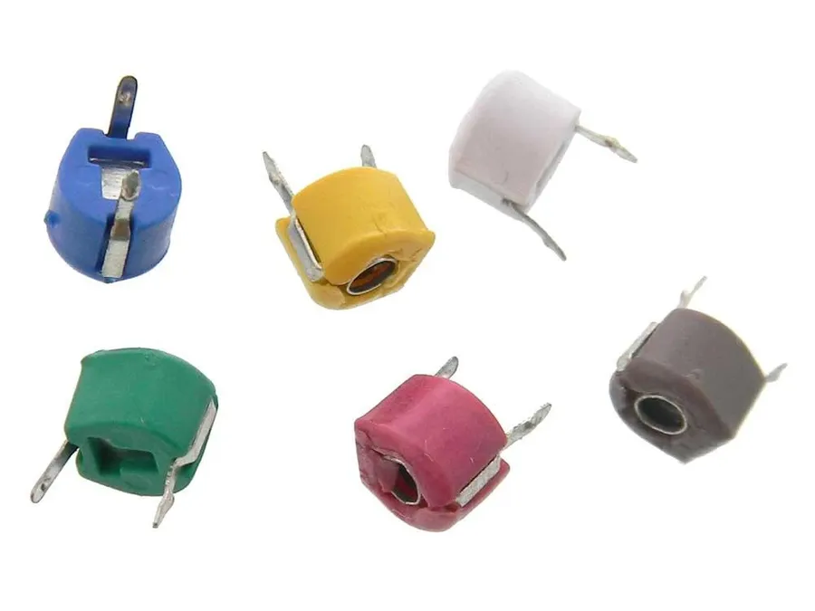
Ceramic trimmer capacitors are compact variable capacitors designed for fine-tuning applications, characterized by their diminutive size and precise adjustability. These capacitors are essential components where space constraints are paramount and the need for accurate capacitance adjustments is critical, often found in precision electronic devices requiring delicate calibration.
The construction of ceramic trimmer capacitors involves a layered structure of ceramic dielectric material between conductive electrodes. Adjustment is typically achieved by a screw or other mechanical means, changing the overlap area or the spacing between the electrodes, altering the capacitance.
Key characteristics of ceramic trimmer capacitors are as follows:
These capacitors find their niche in various applications where precision tuning is essential. They're employed in areas such as:
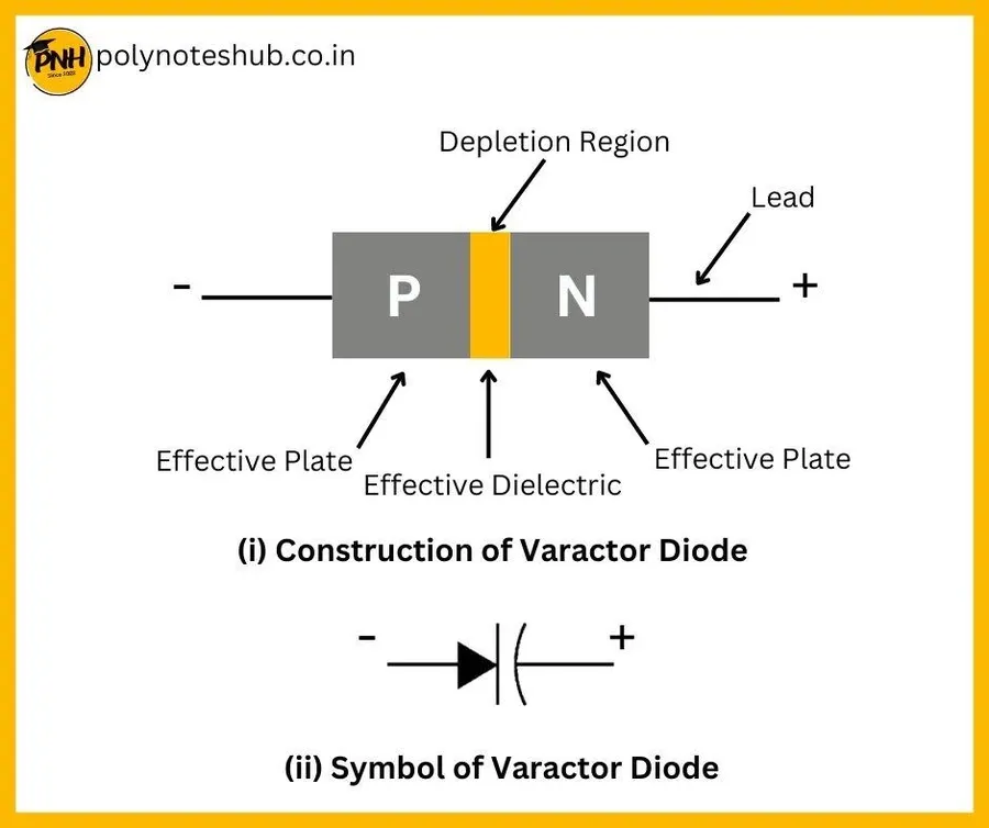
Varactor diodes, also known as varicap diodes or tuning diodes, offer an electronically controllable method of varying capacitance, diverging significantly from the mechanical adjustments of traditional variable capacitors. This control is achieved through manipulation of the diode's reverse bias voltage, influencing the width of its depletion region and, consequently, its capacitance.
The core operational principle of a varactor diode hinges on the behavior of its p-n junction under reverse bias conditions. Applying a reverse bias voltage causes the depletion region—an area devoid of mobile charge carriers—to widen. This widening effectively increases the distance between the 'plates' of the capacitor (formed by the p and n regions), thereby reducing the overall capacitance. Conversely, decreasing the reverse bias voltage narrows the depletion region, increasing capacitance.
This electronic control of capacitance through reverse bias voltage makes varactor diodes highly suitable for applications that demand precision and rapid adjustments, particularly in electronic tuning systems. Unlike mechanical variable capacitors, varactor diodes lack moving parts, providing greater reliability, faster tuning speeds, and smaller physical dimensions.
| Feature | Mechanical Variable Capacitor | Varactor Diode |
|---|---|---|
| Adjustment Method | Mechanical (rotating plates) | Electronic (reverse bias voltage) |
| Tuning Speed | Slower | Faster |
| Reliability | Lower (due to moving parts) | Higher (no moving parts) |
| Physical Size | Larger | Smaller |
| Control Method | Manual or Motor | Electronic Control Circuits |
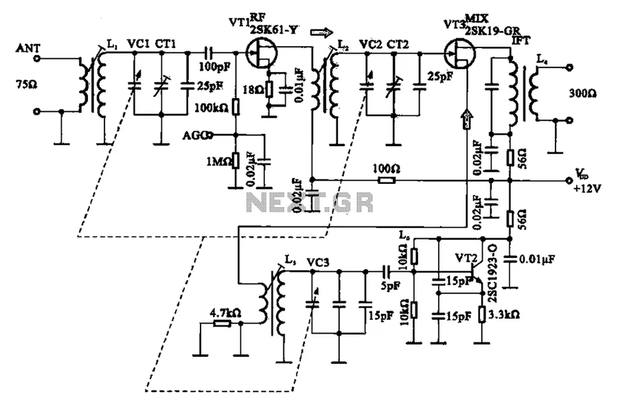
Variable capacitors are indispensable components in a wide array of electronic applications, ranging from traditional radio circuits to sophisticated modern communication systems. Their ability to dynamically adjust capacitance makes them essential for tuning, impedance matching, and frequency control.
| Application | Capacitor Type | Function | Advantages |
|---|---|---|---|
| Traditional Radio Tuning | Air Variable Capacitor | Frequency Selection | High Q factor, mechanical adjustment |
| Electronic Tuning | Varactor Diode | Automatic Frequency Adjustment | Electronic control, rapid tuning |
| Impedance Matching | Variable Capacitor (Air/Ceramic) | Power Transfer Maximization | Adjustable impedance for optimal transfer |
| Oscillator Circuits | Variable Capacitor | Frequency Stability and Tuning | Adjustable resonant frequency, wide range control |
Selecting the appropriate variable capacitor requires careful consideration of several key parameters to ensure optimal performance in a given application. These parameters encompass both electrical characteristics and physical attributes. This section provides a guide to these critical selection criteria.
| Parameter | Description | Considerations |
|---|---|---|
| Capacitance Range | The minimum and maximum capacitance values the device can achieve. | Choose a range that adequately covers the desired application's frequency or tuning requirements. Consider the required tuning range and ensure the capacitor's range aligns with it. |
| Voltage Rating | The maximum voltage the capacitor can withstand without failure or dielectric breakdown. | Select a capacitor with a voltage rating that exceeds the peak voltage expected in the circuit, ensuring reliability and preventing damage. |
| Temperature Coefficient | The rate at which the capacitance changes with temperature variations. | Choose a capacitor with a low temperature coefficient for stable performance across a range of operating temperatures, which is critical in temperature-sensitive applications. |
| Q Factor | A measure of a capacitor's efficiency, indicating energy loss as heat, where higher Q is better. | A higher Q factor minimizes signal loss and ensures better performance in RF applications; consider applications where energy loss is a concern. |
| Mechanical vs. Electronic Control | How capacitance is adjusted: mechanically (screw/rotary) or electronically (varactor). | Mechanical adjustment is suitable for manual tuning, while electronic control is appropriate for automated or digitally controlled systems. Select based on control and integration needs. |
| Size and Form Factor | Physical dimensions and mounting style (SMD, through-hole). | Ensure the physical size and mounting style align with board layout constraints. |
| Tuning Sensitivity | The precision of adjustment, referring to the resolution of capacitance tuning. | Consider the tuning resolution needed for fine adjustments. |
| Dielectric Material | The material that insulates the plates, impacting temperature stability and overall performance. | Select based on the application's requirements, with consideration for factors such as temperature stability and operational frequency. |
This section addresses common inquiries regarding variable capacitors, offering clear and concise answers to help users better understand their characteristics, limitations, and applications. These insights are crucial for effectively utilizing variable capacitors in various electronic designs.
Variable capacitors, while robust, require careful handling and maintenance to ensure optimal performance and longevity. This section outlines common issues and provides practical guidance on troubleshooting and maintaining these components.
Variable capacitors, though often small in size, wield significant power in the electronic world by offering adjustable capacitance. From their mechanical forms in old radios to the advanced electronically controlled versions used today, they play a critical role in tuning and optimizing circuits. Understanding their diverse types and applications allows us to appreciate their importance in past and future technologies, highlighting their enduring value in the realm of electronics. This article offers a solid foundation to better understand variable capacitor applications and selection criteria for a variety of projects.

