
In the high-stakes world of aerospace, a flight controller is only as reliable as its weakest solder joint. As drone performance demands increase, engineers must move beyond basic manufacturing constraints to embrace advanced DFM principles that specifically address vibration, thermal load, and mechanical stress.
Understanding the Dynamic Environment of Flight Controllers

Vibration Dynamics and Mechanical Fatigue
Flight controllers operate in a hostile environment characterized by high-frequency vibrations induced by motors, propellers, and aerodynamic flutter. These vibrations manifest as periodic mechanical loading that can lead to solder joint fatigue, component cracking, and micro-delamination within the PCB laminate. Unlike standard industrial environments, the spectral content of drone vibration often spans across resonance frequencies of surface-mount components, creating a risk of fatigue failure that traditional design practices often overlook.
Thermal Cycling and Material Expansion
Rapid thermal cycling—often transitioning from ambient conditions to extreme heat during peak power maneuvers—triggers significant Coefficient of Thermal Expansion (CTE) mismatches. When a PCB expands and contracts at a different rate than the mounted components, the resulting shear force is concentrated on the solder interconnects. Over hundreds of cycles, this leads to 'solder creep,' ultimately causing intermittent signal loss or catastrophic board failure.
| Stressor | Primary Failure Mode | Design Impact |
|---|---|---|
| High-Frequency Vibration | Solder Joint Fatigue | Requires reinforced mounting and damping. |
| Rapid Thermal Cycling | Interconnect Shear/Creep | Requires CTE-matched substrates/underfill. |
| High G-Loading | Component Pad Lifting | Requires advanced footprint anchoring. |
Critical Reliability Queries
- How does vibration frequency affect component longevity?
Vibrations at the resonant frequency of a component lead to rapid accumulation of fatigue cycles, shortening the mean time between failures (MTBF) exponentially compared to out-of-band vibrations. - Why is CTE mismatch a primary concern for flight electronics?
Flight controllers use high-density components; even minor thermal expansion variances create significant shear stress, potentially snapping fine-pitch BGA balls or pulling pads off the substrate.
Strategic Component Placement and Density Optimization
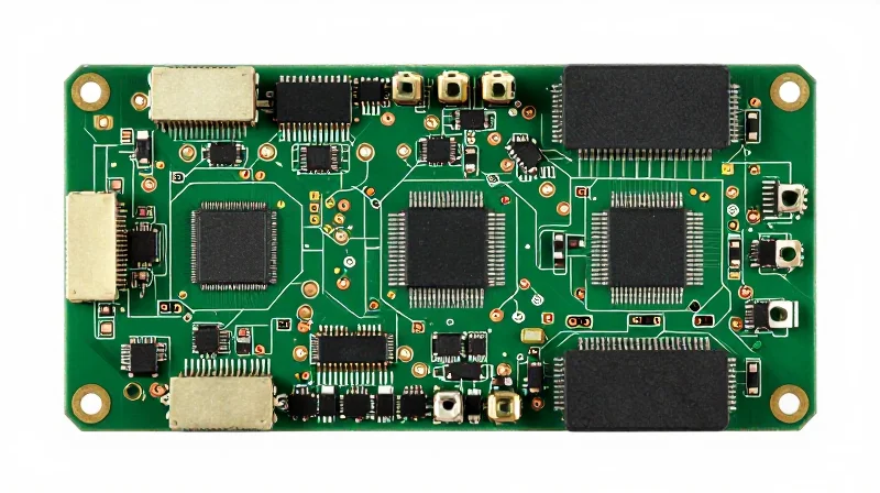
Strategic Component Placement and Density Optimization
Achieving high functional density in flight controller PCBs requires moving beyond mere space efficiency to prioritize structural mechanics. Component placement must be governed by the 'stiffness-to-mass' ratio, ensuring that heavier components do not become levers that exacerbate fatigue during resonant vibration events. By strategically clustering heavy components near board mounting points and distributing lighter, low-profile devices elsewhere, designers can minimize dynamic deflection and avoid stress-induced solder joint failure.
Guidelines for High-Reliability Placement
- Proximity to Mounting Points
Place high-mass components such as large electrolytic capacitors, power inductors, and connectors as close as possible to chassis standoff locations to limit PCB bending moments. - Component Orientation
Align the long axis of elongated surface-mount components parallel to the axis of expected peak vibration where possible to prevent solder joint peeling. - Thermal-Mechanical Decoupling
Avoid placing sensitive oscillators or high-precision sensors near thermally active power stages; implement isolation cuts in the board profile if necessary to decouple mechanical stress pathways.
Comparative Analysis of Density Strategies
| Strategy | Benefit | Trade-off |
|---|---|---|
| Centric Clustering | Reduces center-span board deflection | Increases localized thermal hotspots |
| Peripheral Dispersion | Improved heat dissipation across board | Increases risk of fatigue in trace paths |
| Modular Zoning | Superior EMI and vibration isolation | Increased footprint and PCB complexity |
Effective density management also requires adherence to keep-out zones near board edges. High-frequency vibration often causes the highest displacement at the board center; therefore, critical fine-pitch ICs should be moved away from board mid-sections toward stiffened edge regions to protect against solder fatigue.
Mitigating Resonance through PCB Stack-up Design
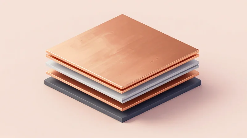
Mitigating resonance requires a proactive approach to mechanical impedance matching through strategic PCB stack-up design. By controlling the board's stiffness-to-mass ratio and utilizing targeted damping layers, designers can shift the PCB's natural frequency outside the operational spectrum of the drone's motors and propellers, thereby preventing catastrophic sensor aliasing and interconnect fatigue.
Structural Stack-up Optimization
The symmetry of the PCB stack-up is paramount to preventing warpage under thermal cycling, which directly impacts vibration resistance. A balanced, symmetrical copper distribution ensures uniform mechanical stress across the substrate.
| Design Factor | Recommendation for Vibration Resistance | Impact |
|---|---|---|
| Stack-up Symmetry | Balanced copper weights on inner layers | Reduces internal stress and warpage |
| Substrate Selection | High Tg (>=170°C) FR-4 or Polyimide | Maintains stiffness under heat loads |
| Layer Thickness | Increased core thickness for high G-loads | Raises fundamental resonant frequency |
Damping and Material Considerations
Incorporating constrained layer damping (CLD) within the PCB stack-up involves integrating a viscoelastic polymer layer between copper or substrate planes. This technique is highly effective at dissipating kinetic energy as thermal energy, significantly reducing the Q-factor of mechanical resonance peaks.
- How does layer count impact resonance?
Increasing layer count can improve stiffness if copper planes are strategically placed to act as rigid internal structural members, effectively 'bracing' the board against flexing. - What role do embedded vias play in vibration?
Vias act as potential stress risers. During vibration, barrels undergo fatigue; utilizing micro-vias and ensuring adequate copper plating thickness (min 25um) is critical to preventing crack propagation in the vias. - Is rigid-flex better than traditional rigid boards?
For flight controllers, rigid-flex can be beneficial as the flexible sections provide mechanical isolation between high-vibration power stages and sensitive sensor zones, acting as a natural damper.
Final validation of your stack-up should involve Modal Analysis simulation during the design phase. By identifying the fundamental natural frequency of the PCB, you can ensure that it does not align with the drone’s motor RPM harmonics (e.g., 100-300Hz), thus avoiding sympathetic resonance.
Advanced Thermal Management for Power-Dense Designs
Thermal Dissipation Strategies for High-G Environments
In flight controllers exposed to extreme vibration, thermal management must address both heat transfer and mechanical fatigue. Standard heat sink mounting methods can lead to resonance or component stress; therefore, developers should prioritize integrated thermal paths such as thermal vias and optimized copper pours that transition heat directly into the structural PCB layers and chassis frames.
Techniques for Reliable Thermal Transfer
- Thermal Via Arrays
Utilize high-density micro-via arrays directly under power components. To prevent solder wicking and voids during vibration cycles, use capped and plated-over vias to ensure a flat, stable mounting surface. - Optimized Copper Pours
Implement thick copper internal layers (2oz or higher) to act as a heat spreader. Ensure these layers are connected to the chassis mounting points to utilize the airframe as a secondary heat sink. - Conformal Thermal Interfaces
Avoid rigid thermal epoxies which may crack under high-frequency load. Select vibration-dampening thermal interface materials (TIM) that maintain elasticity across the full operating temperature range.
Comparison of Thermal Management Approaches
| Method | Vibration Resistance | Thermal Efficiency | Complexity |
|---|---|---|---|
| Active Heat Sinks | Low | Very High | High |
| Thermal Via Arrays | High | High | Low |
| Internal Copper Spreading | Very High | Moderate | Medium |
| TIM Pad Integration | Medium | Moderate | Low |
Design Best Practices for Power-Dense Designs
For power-dense flight controllers, the goal is to minimize the thermal resistance path length while avoiding large mass concentrations that could induce resonance. Symmetrical placement of power stages on both sides of the PCB, linked by staggered via stitching, ensures both uniform heat distribution and better mechanical balance under flight stress.
Solder Joint Integrity Under Constant Mechanical Stress
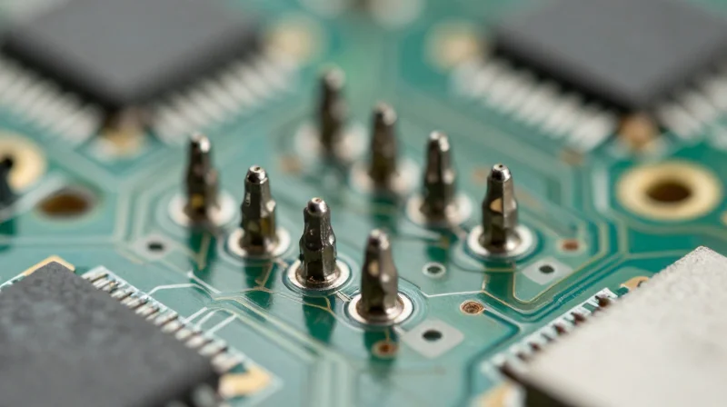
Solder joints in flight controllers act as both electrical interconnects and mechanical anchors. Under constant vibration, these joints endure cyclic loading that leads to work-hardening and eventual crack propagation. Ensuring integrity requires a design shift from standard consumer-grade assemblies toward fatigue-resistant solder alloys and geometry-optimized pad designs that distribute mechanical strain away from the brittle intermetallic compound (IMC) layer.
Selecting Fatigue-Resistant Solder Alloys
Traditional SAC305 alloys, while RoHS compliant, are prone to grain coarsening under thermal-mechanical stress. For harsh environments, doping SAC alloys with elements such as Bismuth (Bi), Antimony (Sb), or Nickel (Ni) is essential to refine grain structure and improve creep resistance.
| Alloy Type | Vibration Resistance | Primary Application |
|---|---|---|
| SAC305 | Low-Medium | Standard consumer electronics |
| SAC-Bi (e.g., Innolot) | High | High-G drone actuators and FCUs |
| Sn-Ag-Cu-Ni | Medium-High | General flight stabilization modules |
Optimizing Pad Geometries for Strain Relief
The geometry of the landing pad dictates the stress profile across the solder fillet. To mitigate fatigue, prioritize NSMD (Non-Solder Mask Defined) pads for fine-pitch components to allow solder to wrap around the pad edges, significantly increasing the shear strength and fatigue life of the joint.
- How does pad shape influence failure?
Square or rectangular pads with sharp corners act as stress risers. Transitioning to rounded-corner or circular pads reduces localized stress concentration during board flex. - Why is solder mask clearance critical?
Excessive mask overlap restricts solder wetting, leading to 'fillet necking' which creates a weak point where fatigue cracks initiate under high-frequency oscillation. - How should I design for BGA components?
Increase the via-in-pad distance and utilize high-ductility solder paste formulations to accommodate the high CTE (Coefficient of Thermal Expansion) mismatch between the silicon die and the PCB substrate.
Process Control for Joint Integrity
Beyond design, the soldering process must ensure a consistent IMC layer. Excessive dwell time during reflow leads to overly thick brittle layers. Implementing precise oxygen-controlled reflow profiles minimizes oxidation and ensures high-integrity metallurgical bonding.
DFM Rules for High-Reliability Interconnects
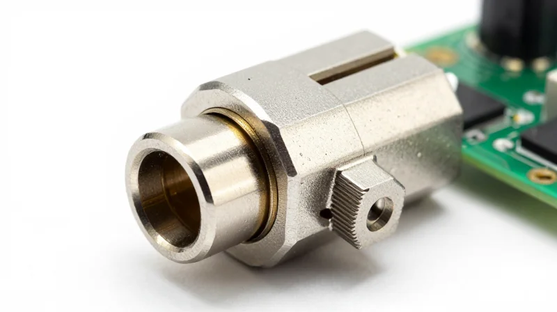
High-reliability interconnects are the primary point of failure in vibration-prone aerospace systems. To maintain signal continuity under harsh loads, designers must transition from standard consumer-grade headers to locking mechanisms that prevent mechanical fretting and intermittent disconnections. A holistic approach combines board-level strain relief with advanced connector geometry to isolate signal paths from the mechanical resonance of the airframe.
Connector Selection and Mechanical Hardening
When selecting connectors for high-vibration environments, prioritize components rated for high mating cycles and vibration resistance. Avoid friction-lock connectors which rely solely on plastic tension, as these degrade rapidly under thermal cycling and resonant loads.
| Connector Type | Reliability | Best Use Case |
|---|---|---|
| Standard Pin Headers | Low | Prototyping only |
| Locking JST-GH/SH | Medium | Low-mass signals |
| Micro-D / Circular | High | Mission-critical power/data |
Advanced Strain Relief and Cable Management
Cables act as mechanical levers that translate frame vibrations directly into torque on the solder joints. Effective DFM requires mitigating this force before it reaches the PCB. Utilize potting compounds around connector bases and mechanical tie-down points to distribute stress away from the board surface.
- How can I prevent cable-induced stress on solder joints?
Implement mechanical 'service loops' in wire routing to decouple frame movement from the PCB, and apply RTV silicone or structural epoxy at the cable-PCB interface. - What is the role of conformal coating in interconnect reliability?
Beyond environmental protection, high-viscosity conformal coatings provide a mechanical bridge between the connector shell and the PCB, effectively dampening micro-vibrations that cause fretting corrosion.
DFM Checklist for Interconnects
Ensure that every connector is properly supported by the enclosure or an internal bracket. Relying solely on the PCB solder joints to hold a cable's weight under a 10G or 20G flight load will inevitably lead to fatigue failure. Always design for secondary mechanical fixation such as mounting holes for screw-down connectors.
Verification Testing: Simulating Field Conditions

Validated Testing Frameworks
To confirm that your DFM strategies—such as component underfilling, stiffener placement, and solder joint geometry—are effective, you must subject the flight controller to accelerated life testing (ALT). These protocols replicate the cumulative fatigue of thousands of flight hours in a compressed timeframe, exposing design flaws before high-volume manufacturing.
Key Simulation Methodologies
| Test Type | Primary Goal | Vibration Characteristic |
|---|---|---|
| Random Vibration | Identify structural resonance | Broadband frequency excitation |
| Sine-on-Random | Simulate motor harmonics | Overlay of discrete tones |
| HALT/HASS | Define operating limits | High-stress environmental screening |
Frequently Asked Questions
- How does thermal cycling affect vibration resistance?
Thermal cycling induces CTE mismatch stresses that weaken solder joints over time, making them significantly more prone to brittle fracture when subjected to mechanical vibration. - What is the most critical failure mode during testing?
Solder joint fatigue—specifically at high-mass BGA components or connectors—is the primary failure point, often manifesting as intermittent electrical signals before total circuit failure. - Should I test bare boards or fully enclosed systems?
Testing should occur at both levels; bare boards reveal PCB deflection risks, while enclosed testing identifies resonance induced by housing interaction and cable whip.
Monitoring signal integrity during testing is paramount. Use high-speed data loggers to capture 'micro-interrupts'—transient opens in solder joints that occur for just a few microseconds under vibration. These events are often the precursors to permanent failures and provide the most actionable data for refining your DFM layout.
Conclusion: Building for Failure-Proof Performance
Synthesizing Mechanical and Electrical Integrity
The transition from standard PCB design to vibration-resistant flight controller engineering necessitates a departure from cost-optimized layouts toward reliability-optimized architectures. By aligning solder joint metallurgy, strategic component placement, and advanced strain-relief techniques, designers transform the PCB from a fragile collection of components into a robust, high-performance platform capable of enduring sustained harmonic loads.
| Focus Area | Reactive Approach | Proactive DFM Strategy |
|---|---|---|
| Solder Interconnects | Standard SAC305/Reflow | Doped alloys + Controlled fillet profiles |
| Component Stress | Edge-mounting | Center-of-gravity optimization & potting |
| Validation | In-circuit functional test | Combined thermal-vibration (HALT/HASS) |
Key Takeaways for Long-Term Lifecycle Management
- Does DFM for vibration increase total project cost?
While initial DFM implementation incurs higher NRE costs and requires specific components, it significantly reduces the Total Cost of Ownership (TCO) by minimizing field failures and warranty claims. - How does PCB thickness influence resonance?
Thicker boards increase structural rigidity and raise the natural frequency of the assembly, which helps decouple the PCB from the primary vibration modes found in typical drone motors and rotors. - Is software compensation a substitute for physical DFM?
No; while advanced PID tuning can mask minor jitter, it cannot address the underlying physical degradation of solder joints and mechanical connectors. Physical durability remains the foundation of flight safety.
Ultimately, the design of a vibration-resistant flight controller is an iterative process. As mission profiles become more demanding and motor RPMs increase, the data gathered from field performance must feed back into the DFM library. Embracing these advanced guidelines ensures that the hardware remains the most reliable component in the flight stack, guaranteeing mission success in even the most volatile environments.
By adhering to these rigorous DFM standards, you transition your drone electronics from prototype status to flight-proven reliability. Don't leave your hardware performance to chance; contact our engineering team today to review your current PCB designs for mission-critical durability.
