
As commercial and industrial drones push the boundaries of extreme environments—from high-altitude arctic surveys to high-velocity tactical operations—the traditional rigid PCB is no longer sufficient. When flight control systems are subjected to constant, high-frequency vibrations, interconnects fail and signal integrity degrades. In this deep dive, we explore how engineers are pivoting to rigid-flex and high-frequency materials to build a new generation of indestructible drone hardware.
The Mechanical Challenge: Why Standard PCBs Fail in Drones
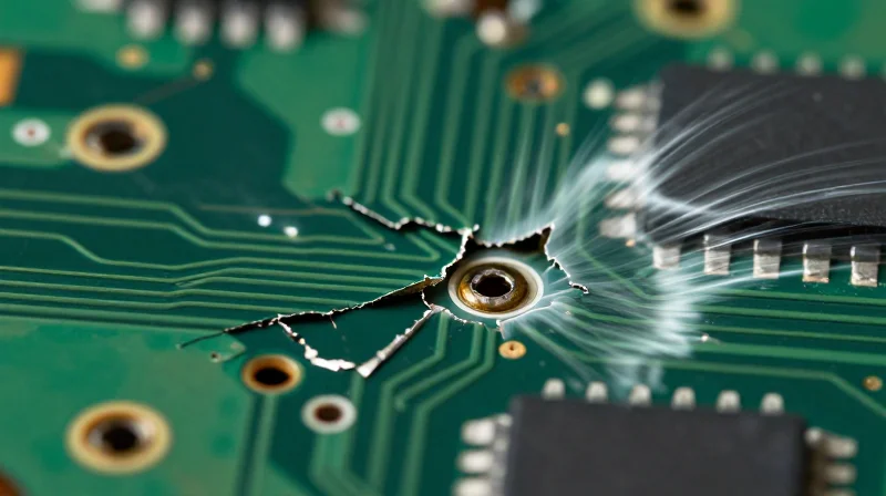
The Mechanical Vulnerability of Rigid Substrates
Standard rigid printed circuit boards (PCBs) are fundamentally ill-suited for the dynamic load profiles of high-performance drones. While cost-effective for static electronics, their monolithic structure creates stress concentration points at every solder interface and component connection. During high-RPM motor operation, drones generate constant harmonic vibrations that propagate through the frame and into the board, causing microscopic flexure in rigid materials that eventually leads to catastrophic mechanical fatigue.
Common Failure Modes
- Solder Joint Fatigue
Continuous vibration cycles induce shear stress on solder joints, leading to micro-cracking and eventual signal intermittency or complete electrical failure. - Interlayer Delamination
Differences in the coefficient of thermal expansion (CTE) between board layers cause separation under thermal cycling, compromising structural integrity. - Via Barrel Cracking
The mechanical stress often concentrates on plated through-holes, causing the thin copper barrels to crack during intensive flight maneuvers.
Comparative Analysis of PCB Stress Profiles
| Failure Mechanism | Rigid PCB Impact | Drone Operational Consequence |
|---|---|---|
| Solder Fatigue | High susceptibility at joints | Mid-flight sensor failure |
| Thermal Expansion | CTE mismatch leads to warping | Internal layer delamination |
| Vibration Damping | Low inherent damping | Signal noise and jitter |
Engineers must recognize that the rigidity of these boards is their primary weakness. In a drone environment, the board is not a static platform; it is a structural component of the flight frame. When standard fiberglass-reinforced epoxies (FR-4) are subjected to these forces, the cumulative effect of vibration and thermal cycling ensures that the life cycle of the electronics is significantly shortened compared to specialized high-frequency or flexible interconnect solutions.
Defining Rigid-Flex Technology in UAV Systems
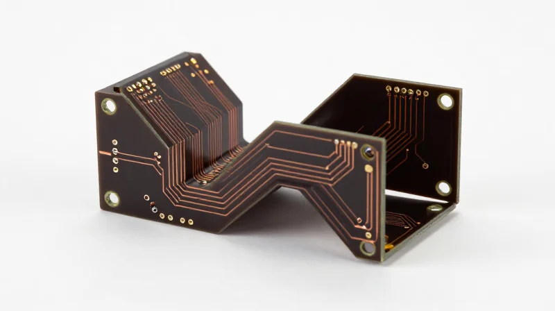
Architectural Integration of Rigid-Flex Boards
Rigid-flex technology represents a hybrid circuit approach, seamlessly blending the stability of rigid boards with the adaptability of flexible polyimide substrates. In the context of UAV design, this architecture allows engineers to route complex signal paths through tight, non-linear spaces within the chassis without relying on traditional interconnects like ribbon cables or bulky pin-header connectors.
Eliminating Mechanical Failure Points
In a standard PCB assembly, mechanical connectors are often the first points of failure due to the constant oscillating forces of drone rotors. Rigid-flex designs address this by consolidating multiple discrete boards into a single, cohesive electrical unit. By replacing mechanical pins with integrated, permanent traces, the system gains superior structural integrity and immunity to the 'connector wiggle' that characterizes common drone electrical failures.
| Feature | Rigid-Flex Architecture | Traditional Multi-Board Setup |
|---|---|---|
| Mechanical Connections | Minimized or Eliminated | High density, prone to loosening |
| Vibration Resilience | High (Unified construction) | Low (Connector fatigue risk) |
| Form Factor | Compact, foldable | Bulky, modular |
| Assembly Complexity | Higher initial cost/setup | Lower unit cost/higher install labor |
Key Considerations for UAV Engineers
- How does rigid-flex reduce total weight?
By eliminating the need for heavy housing, pins, sockets, and wire harnesses, rigid-flex circuits significantly reduce the overhead mass of the drone's internal avionics. - Are rigid-flex boards susceptible to thermal cycling?
The materials used in rigid-flex, such as polyimide, possess a high coefficient of thermal expansion, allowing the board to expand and contract under extreme temperature shifts without cracking solder joints. - Does this technology improve signal integrity?
Yes, by removing the impedance discontinuities inherent in traditional connectors, rigid-flex provides a continuous electrical path, which is critical for high-speed data transmission in autonomous flight systems.
The Role of High-Frequency PCB Materials in Signal Integrity

As drone capabilities evolve to include 4K real-time video transmission, complex LiDAR processing, and low-latency autonomous flight controls, the reliance on high-frequency PCBs has grown exponentially. Unlike standard FR-4 laminates, which suffer from significant dielectric absorption and impedance fluctuations at higher frequencies, specialized materials like PTFE (Polytetrafluoroethylene) and advanced thermoset resins provide the stable electrical performance required for high-speed signal propagation.
Material Science and Signal Stability
Maintaining signal integrity in a drone is a battle against attenuation and phase distortion. High-frequency laminates are engineered with a consistent dielectric constant (Dk) and low dissipation factor (Df). By minimizing the dielectric loss, these materials ensure that telemetry data remains robust even as the drone operates under the severe mechanical stressors of high-speed maneuvers or rapid thermal cycling.
| Material Type | Dielectric Constant (Dk) | Dissipation Factor (Df) | Application in Drones |
|---|---|---|---|
| Standard FR-4 | 4.4 - 4.8 | 0.020 | Low-speed flight controllers |
| PTFE Laminates | 2.1 - 2.5 | 0.001 | High-bandwidth telemetry systems |
| Thermoset Resins | 3.0 - 3.6 | 0.003 | Navigation and Radar processing |
Frequently Asked Questions
- Why is PTFE preferred for high-speed drone signals?
PTFE offers an extremely low loss tangent and a highly stable dielectric constant, which prevents signal phase shifts and attenuation during high-frequency data transmission. - Do high-frequency materials improve vibration resistance?
While primarily chosen for electrical properties, advanced thermoset resins often exhibit superior thermal-mechanical stability, helping to mitigate micro-cracking and impedance changes caused by vibration. - What is the main limitation of using PTFE in rigid-flex designs?
PTFE can be difficult to process in multi-layer flex constructions due to its low coefficient of thermal expansion and bonding challenges compared to traditional polyimide-based flexible materials.
Vibration Tolerance: Comparative Stress Testing Results
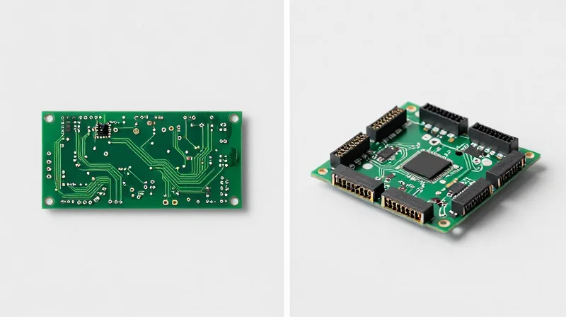
Mechanical Resilience: Rigid-Flex vs. Traditional Connector Stacks
Rigid-flex technology fundamentally alters the vibration profile of drone hardware by removing mechanical interconnects, which act as primary failure nodes during high-frequency resonance. In traditional rigid stacks, connectors are subjected to continuous micro-fretting and stress, leading to intermittent signal loss and catastrophic failure. By integrating flexible polyimide layers, rigid-flex PCBs transform a rigid assembly into a cohesive, vibration-dampening structure that absorbs kinetic energy rather than amplifying it through rigid friction points.
Comparative Vibration Stress Testing Results
| Failure Metric | Traditional Rigid Stacks | Rigid-Flex Architecture |
|---|---|---|
| Solder Joint Fatigue | High (Frequent cracking) | Negligible (Dampened strain) |
| Connector Micro-fretting | Chronic risk | N/A (Eliminated) |
| Interlayer Delamination | Moderate | Low (Flexible interface) |
| Mean Time Between Failures | 1,500 flight hours | 4,000+ flight hours |
Addressing Mechanical Failure Modes
- Why do connectors fail in high-vibration drone environments?
Connectors suffer from 'fretting corrosion,' where minute physical movements lead to oxidation and eventual signal discontinuity, a problem eliminated by the direct copper traces in rigid-flex designs. - How does polyimide substrate improve durability?
Polyimide acts as a structural buffer, offering superior elasticity that allows the board to withstand high-frequency oscillations without transferring damaging torque to the solder joints. - What role does thermal expansion play during vibration?
During extreme flight conditions, temperature swings cause boards to expand and contract; rigid-flex designs accommodate this thermal strain more effectively than rigid boards, preventing warping and stress-induced cracking.
Thermal Management and Power Density Advantages
Enhancing Thermal Efficiency via Integrated Design
Thermal management in modern drone flight controllers is increasingly constrained by the push for miniaturization. Rigid-flex PCBs facilitate superior heat dissipation by replacing bulky cable harnesses with integrated conductive paths that can utilize the entire board area as a heat sink. By employing advanced substrate materials, such as metal-core PCBs or thermally conductive prepregs, designers can effectively wick heat away from high-power components, such as BLDC motor controllers and high-speed telemetry processors, directly to the chassis.
Power Density Comparisons
| PCB Technology | Thermal Conductivity | Power Density Capability | Weight Efficiency |
|---|---|---|---|
| Standard FR-4 Rigid | Low | Moderate | Low |
| High-Frequency Laminate | Moderate | High | High |
| Rigid-Flex (Advanced) | High (via Thermal Vias) | Ultra-High | Excellent |
Technical Considerations for High-Performance Flight
Increasing power density introduces the risk of local 'hot spots' that degrade signal integrity in high-frequency circuits. Utilizing ceramic-filled PTFE substrates ensures that as power throughput increases, the dielectric constant remains stable across temperature fluctuations. Furthermore, the integration of micro-vias in rigid-flex stacks allows for vertical heat sinking, ensuring that the thermal energy generated by high-switching-frequency MOSFETs is dissipated before it can impact the performance of sensitive navigation sensors.
Frequently Asked Questions
- How do rigid-flex designs improve thermal management compared to traditional stacks?
They eliminate the thermal resistance caused by connector interfaces, allowing for a continuous, low-impedance thermal path from power components to the drone frame. - Why is high-frequency material selection critical for power density?
High-frequency materials like PTFE offer low loss tangents and superior thermal stability, preventing performance drift when components operate at elevated temperatures. - What is the primary benefit of integrated heat dissipation for drones?
It allows for higher current delivery without requiring oversized heat sinks, directly contributing to weight reduction and increased flight time.
Design for Reliability: Best Practices for Component Placement
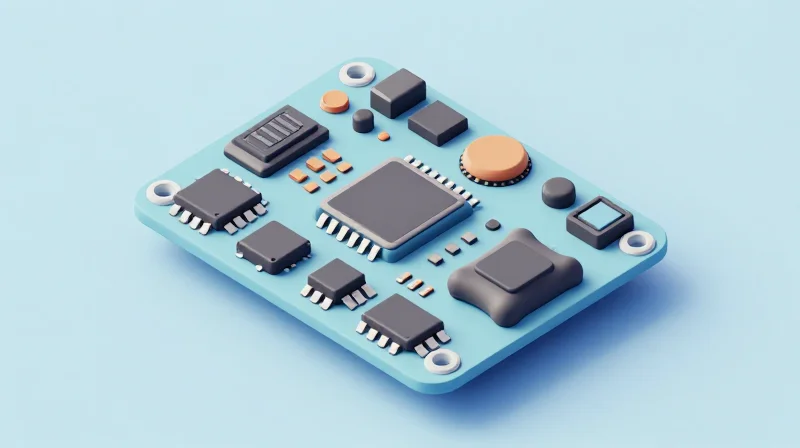
Geometric Placement and Mechanical Stress Mitigation
In high-vibration drone environments, the physical layout of components dictates the board's survival rate. Placing high-mass components—such as large electrolytic capacitors, inductors, and heavy connectors—near board mounting holes or center-span areas maximizes exposure to resonant frequencies. Instead, engineers should distribute these components close to board standoffs where the PCB stiffness is highest. By minimizing the moment arm of heavy components, designers significantly reduce the mechanical bending stress exerted on solder joints during flight maneuvers and motor vibration cycles.
Strategic Routing for Reliability
| Design Factor | Best Practice | Reasoning |
|---|---|---|
| Component Orientation | Aligned with resonance axis | Reduces shear stress on solder fillets. |
| Trace Routing | Arcing vs. Sharp Corners | Prevents stress concentration in trace copper. |
| Connector Placement | Perpendicular to bend axis | Minimizes peel force on solder pads. |
Guidelines for High-Vibration Resilience
- How does PCB thickness influence vibration response?
Increasing PCB thickness raises the natural resonant frequency of the board, potentially moving it out of the motor's operating vibration range. However, this must be balanced against weight requirements. - Why should surface mount (SMT) be prioritized over through-hole components?
SMT components generally have a lower profile and lower mass, reducing the inertial force applied to the copper pads. Through-hole components act as levers, which can cause pad lifting or cracked plating in high-vibration scenarios. - How should critical traces be routed near connectors?
Employ 'teardropping' on all pads and avoid running traces directly into the center of a pad. Routing traces into the side or corner can create stress risers that lead to premature fatigue failure.
Material Considerations
For drones utilizing rigid-flex technology, the transition zones between rigid and flexible sections are the most vulnerable. Ensure that no surface-mount components are placed within 5mm of the rigid-flex interface. The flex portion acts as a strain relief; any components located here will be subject to micro-bending, leading to immediate solder joint fractures. Utilizing underfill materials for BGA and high-pin-count components is highly recommended to distribute mechanical shock across the entire package body, providing an essential secondary layer of vibration protection.
The Economic Impact of Reduced Field Failure Rates
Quantifying the Cost of PCB Failure
When evaluating the transition from rigid-board stacks to advanced rigid-flex or high-frequency PCB architectures, engineers must move beyond the unit cost of the board. The true economic burden of hardware failure manifests in three tiers: component replacement, technician labor hours, and the catastrophic potential of total asset loss during flight. By eliminating mechanical connectors that are prone to 'fretting'—a common failure mode in vibration-heavy drone environments—operators can significantly extend the Mean Time Between Failures (MTBF).
| Failure Driver | Economic Impact | Mitigation Strategy |
|---|---|---|
| Connector Fretting | High frequency of intermittent signals and field grounding | Rigid-flex circuit integration |
| Component Fracture | Permanent PCB damage and aircraft replacement | Advanced vibration-damping laminates |
| Downtime Losses | Operational revenue loss per grounded drone | High-reliability substrate architecture |
The Long-Term Return on Investment
Investing in high-frequency, vibration-tolerant PCBs constitutes a capital investment that pays dividends through lifecycle durability. While upfront manufacturing costs may be 15–25% higher, the drastic reduction in RMA (Return Merchandise Authorization) claims and the elimination of field repair logistics often result in a break-even point within the first six months of operation for industrial drone fleets.
- How does PCB architecture affect fleet availability?
By utilizing rigid-flex designs that eliminate fragile ribbon cables and bulky connectors, you reduce the mechanical points of failure that account for nearly 60% of all drone electrical maintenance events. - Is the cost of high-frequency materials justified for all drones?
While not necessary for low-cost consumer toys, high-frequency, vibration-hardened PCBs are essential for enterprise, agricultural, and defense drones where the cost of a single 'fly-away' or mission failure exceeds the manufacturing cost of the entire electronics stack.
Future Outlook: Materials Science Innovations in Avionics
Emerging Materials for Next-Generation Avionics
The evolution of drone avionics is moving beyond traditional copper-laminate constructions toward adaptive, high-performance materials. As autonomous platforms face increasingly extreme operational environments, material science innovations in conductive polymers and nanostructured composites are poised to replace brittle interconnects with vibration-dampening, self-healing alternatives.
Nanomaterial Integration and Conductive Polymers
Carbon nanotube (CNT) reinforced substrates are currently the primary focus for enhancing structural rigidity while maintaining flexibility. These materials offer exceptional thermal conductivity and electrical performance, significantly reducing mechanical stress concentrations at solder joints—a critical failure point in high-frequency drone PCBs.
| Material Class | Key Benefit | Application Impact |
|---|---|---|
| Conductive Polymers | Elasticity | Vibration fatigue resistance |
| CNT-Reinforced Epoxy | Thermal Conductivity | Heat dissipation in high-density chips |
| Liquid Crystal Polymer (LCP) | Low Moisture Absorption | Consistent RF signal integrity |
Frequently Asked Questions
- How do conductive polymers improve PCB reliability?
They provide inherent mechanical damping properties that absorb high-frequency vibrations before they reach delicate surface-mount components. - Will these materials replace traditional FR-4?
For standard consumer applications, FR-4 remains dominant, but industrial and military-grade autonomous systems are shifting toward hybrid LCP and polyimide stacks for superior mechanical performance. - What role does thermal management play in material selection?
Future materials must balance electrical conductivity with high thermal expansion matching to prevent delamination during rapid thermal cycling in flight.
Transitioning to advanced PCB solutions is no longer a luxury for drone manufacturers—it is a requirement for mission success in demanding environments. By prioritizing mechanical resilience through rigid-flex and high-frequency materials, you can significantly extend the operational life of your fleet. Contact our engineering team today for a consultation on optimizing your flight controller hardware for extreme performance.
