
In the high-stakes world of medical infusion controllers, a PCB is more than a collection of traces—it is a critical life-support component. As demand for miniaturization and higher accuracy grows, engineers face the dual challenge of meeting stringent FDA/IEC standards while optimizing for manufacturability. This guide breaks down the technical DFM protocols necessary to ensure your medical hardware is both reliable and ready for mass production.
The Regulatory Landscape: Integrating DFM with Compliance
Navigating IPC-6012 Class 3 Compliance
For medical infusion control systems, where reliability is a prerequisite for patient safety, IPC-6012 Class 3 standards serve as the foundational regulatory requirement. Integrating DFM practices with these standards is not merely about board manufacturability; it is about guaranteeing the integrity of critical circuits under varying environmental stress. Designing to Class 3 requires stricter tolerances on annular ring dimensions, copper plating thickness, and dielectric spacing, which must be accounted for during the initial PCB layout phase to prevent costly re-spins and regulatory delays.
Regulatory Design Impact Comparison
| Feature | Standard (IPC-6012 Class 2) | Advanced (IPC-6012 Class 3) |
|---|---|---|
| Annular Ring | Reduced allowed | Minimum 50 micron |
| Plating Thickness | Standard | Minimum 25 micron in barrels |
| Inspection | Visual/Standard | Automated Optical/X-Ray |
| Dielectric Spacing | Nominal | Increased for reliability |
Frequently Asked Questions on Regulatory DFM
- How does DFM affect FDA or regulatory submission speed?
Proactive DFM alignment with Class 3 standards ensures that your board is robust from the start, minimizing non-conformances during manufacturing audits and reducing the documentation burden during the submission process. - Can I use standard design rules for high-accuracy medical devices?
Standard design rules often fail to meet the thermal cycling and mechanical integrity requirements of high-accuracy infusion pumps, potentially leading to field failures and regulatory non-compliance. - Why is copper thickness critical in Class 3 medical designs?
Uniform copper plating in hole barrels is vital to prevent cracked joints during thermal expansion cycles, which could lead to intermittent signal failures in infusion control algorithms.
High-Density Interconnect (HDI) Strategies for Compact Controllers
Strategic Implementation of Microvia Technology
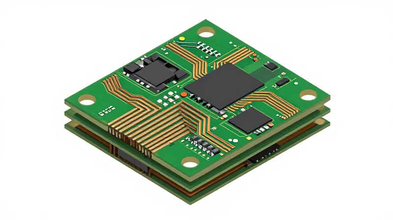
To achieve the high pin density required for medical infusion systems, designers must leverage laser-drilled microvias (Type I, II, or III structures). Unlike traditional mechanical through-hole vias, microvias minimize signal degradation and reduce stubs, which is vital for high-accuracy sensor data acquisition. For high-reliability controllers, DFM rules dictate that microvias should be primarily 'stacked' or 'staggered' in a 1-N-1 or 2-N-2 configuration to maintain structural integrity under thermal cycling.
| Via Technology | Design Constraint | Reliability Impact |
|---|---|---|
| Laser Microvia | Aspect ratio < 0.75:1 | Superior for signal integrity |
| Stacked Vias | Requires filled copper | Higher density; stress concentration risk |
| Blind/Buried Vias | Layer alignment tolerance | Reduces parasitic capacitance |
DFM Rules for Blind and Buried Via Structures
The use of blind and buried vias allows for smaller footprint controllers, but improper layer transitions frequently lead to manufacturing defects. Adhere to these DFM best practices to ensure high yields:
- Aspect Ratio Limits
Keep microvia aspect ratios below 0.75:1 to ensure complete copper plating and prevent barrel cracking during reflow. - Via Filling Requirements
Utilize conductive or non-conductive epoxy filling followed by copper plating (via-in-pad) to ensure a flat, reliable surface for fine-pitch BGA mounting. - Stack-up Symmetry
Maintain a balanced PCB stack-up design to prevent board warpage, which is a common point of failure for high-accuracy medical instrumentation.
Mitigating Manufacturing Risks in HDI Assemblies
For infusion control hardware, signal integrity is as critical as physical robustness. To mitigate risks, perform iterative DFM checks to ensure that the transition between microvias and inner layers does not create unintended impedance discontinuities. Furthermore, engage your fabricator early to verify registration tolerances for sequential lamination cycles, as cumulative layer misalignment remains the leading cause of rejection in HDI-based medical boards.
Advanced Thermal Dissipation Tactics for Reliable Operation

Engineered Thermal Dissipation for Precision Circuits
In high-accuracy medical infusion controllers, thermal fluctuations directly translate to drift in sensor readings and actuator performance. Designers must implement a thermal strategy that minimizes the junction-to-ambient resistance through deliberate copper geometry and advanced material utilization rather than relying solely on forced air cooling.
Strategic Thermal Via Arrays and Plane Stitching
Thermal vias act as primary conduits for heat transfer from top-side power devices to internal ground planes. For medical-grade assemblies, prioritize the use of solid-filled and copper-capped microvias to prevent solder wicking and ensure uniform thermal mass. Avoid standard through-hole vias in high-density areas; instead, employ staggered arrays beneath thermal pads to maximize copper connectivity without creating structural voids.
| Technique | Primary Benefit | DFM Consideration |
|---|---|---|
| Copper-Filled Vias | Optimal Thermal Conductivity | Increases manufacturing lead time |
| Thermal Plane Stitching | Lowers global board temperature | Must avoid impedance discontinuity |
| Component Sinking | Direct heat extraction | Requires custom chassis clearance |
Thermal Management FAQs
- Why is thermal via diameter critical for infusion systems?
Smaller, consistent diameters reduce the risk of thermal shock during soldering and ensure that the plating process deposits a uniform, high-conductivity copper wall. - How does PCB material affect cooling?
Selecting high-Tg (glass transition temperature) laminates prevents structural degradation at sustained operating temperatures, ensuring consistent dielectric performance over the life of the medical device. - Should heat sinks be soldered to the PCB?
In medical environments prone to vibration, mechanical mounting with thermal interface material (TIM) is preferred over direct soldering to prevent stress fractures in the solder joints.
Mastering Signal Integrity in Sensitive Sensing Loops

Mitigating EMI in Sensitive Sensing Loops
For infusion control systems, maintaining high-accuracy signal integrity relies on isolating sensitive analog front-ends from digital switching noise. Practitioners must utilize differential pair routing for all sensor inputs and maintain a strict separation between analog ground (AGND) and digital ground (DGND) planes to prevent ground bounce and crosstalk from degrading dose delivery precision.
| Design Factor | Best Practice | Impact on Accuracy |
|---|---|---|
| Trace Routing | Differential Pairs | Common-mode noise rejection |
| Grounding | Star Grounding | Minimizes ground loop currents |
| Via Usage | Stitching Vias | Provides low-impedance return path |
Frequently Asked Questions on Signal Integrity
- How can I minimize capacitive coupling in dense infusion controllers?
Increase the clearance between sensitive analog traces and high-speed switching lines by at least three times the dielectric thickness, and utilize guard traces grounded at both ends to intercept potential EMI. - Is a split ground plane necessary for medical sensors?
While split planes can be risky, they are often necessary in high-accuracy infusion systems. Ensure that no signal trace crosses the split, as this creates massive loop areas that function as radiating antennas. - What is the role of decoupling capacitors in sensor loops?
Place capacitors as close to the power pins of the sensing IC as possible. Using a combination of values (e.g., 0.1µF and 10pF) helps bypass both high-frequency switching noise and lower-frequency ripple.
/* Impedance matching snippet for sensitive sensing traces */
const signalImpedance = 50; // Ohms
const traceWidth = 0.127; // mm (5 mil)
// Ensure strict adherence to controlled impedance stackup for differential pair routing
Component Placement and Manufacturability Optimization
Strategic Component Placement for AOI Accessibility
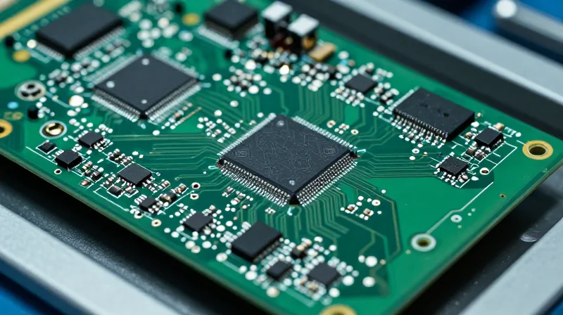
In high-accuracy medical infusion pumps, assembly reliability is contingent upon the precision of component placement and the visibility afforded to AOI systems. Proper component orientation and spacing are critical to prevent shadowing effects that impede image capture and defect detection. Designs should prioritize uniform component alignment and provide adequate keep-out zones to ensure that sensors can detect solder joint anomalies, polarity marks, and bridge defects without mechanical obstruction.
Design Guidelines for Manufacturing Yield
| Requirement | Best Practice for Medical PCBA | Reasoning |
|---|---|---|
| Component Orientation | Align identical packages in the same axis | Simplifies AOI programming and reduces pick-and-place nozzle errors |
| Component Spacing | Minimum 0.5mm clearance for high-density | Ensures adequate accessibility for inspection cameras and thermal airflow |
| Polarity Markers | Clearly visible in all orientations | Prevents reverse mounting of critical dosing control ICs |
Frequently Asked Questions on Assembly DFM
- How does component density impact AOI accuracy?
High component density often causes 'shadowing,' where taller components obscure the solder joints of smaller neighboring parts, forcing the AOI system to miss potential defects. - Why is the keep-out zone critical for medical controllers?
Keep-out zones prevent interference with high-speed sensor loops and ensure that automated equipment has sufficient clearance to maneuver, reducing the risk of collision and board stress during assembly. - Can solder mask colors affect assembly quality?
Yes, high-contrast solder mask colors significantly improve the performance of AOI systems, making it easier to distinguish between the PCB substrate and metal solder joints.
Material Selection and Stackup Design for Medical Environments
Material Selection for Clinical Durability
In infusion control systems, the PCB is frequently exposed to chemical disinfectants and varying thermal cycles. Choosing substrates with high Glass Transition Temperatures (Tg) and low Moisture Absorption levels is critical to preventing mechanical failure or dielectric degradation. High-reliability medical applications typically require laminate materials certified under UL 94V-0 with high CTI (Comparative Tracking Index) ratings to prevent electrical shorts caused by environmental contaminants.
| Material Property | Medical Grade Requirement | Rationale |
|---|---|---|
| Tg (Glass Transition) | > 170°C | Maintains structural integrity during heat spikes. |
| Moisture Absorption | < 0.1% | Prevents delamination during sterilization. |
| CTI Rating | PLC 0 (600V+) | Reduces conductive filament growth risk. |
Stackup Design Principles for Infusion Systems
A balanced and symmetric stackup is the foundation of high-accuracy medical devices. To minimize board warpage—which can lead to cracked solder joints over time—the stackup must utilize copper-balanced layers. Furthermore, incorporating internal ground planes serves a dual purpose: providing a stable reference for sensitive flow-sensing signals and acting as a barrier against electromagnetic interference (EMI) ingress.
- Why is layer symmetry vital?
Symmetry prevents mechanical stress and board twisting, which are significant failure modes in high-accuracy infusion pumps subjected to physical handling. - How does stackup affect EMI compliance?
Strategic placement of signal layers between solid ground planes (stripline configuration) significantly reduces radiated emissions, ensuring the device meets stringent medical EMC standards. - Are there specific requirements for medical-grade laminates?
Laminates must be halogen-free to comply with modern safety standards regarding toxicity in the event of component combustion or failure.
Recommendations for High-Accuracy Environments
Designers should specify high-performance epoxy resins with optimized glass weave styles (such as flat-glass or low-profile glass) to minimize the fiber-weave effect. This mitigation is essential when routing high-speed signal lines for precision dose monitoring, as it ensures consistent dielectric constants across the signal path.
DFM Verification and Pre-Production Analysis

The Necessity of Pre-Production DFM Verification
In the development of medical infusion control systems, where dose precision and operational reliability are non-negotiable, pre-production DFM verification acts as the final safety buffer. Advanced software tools systematically audit layout files for potential fabrication and assembly anomalies that human review may miss, effectively eliminating the risk of costly re-spins and ensuring that the high-density interconnects required for sensitive sensing electronics remain within manufacturing tolerances.
Automated Analysis vs. Manual Inspection
| Feature | Manual Review | Automated DFM Analysis |
|---|---|---|
| Consistency | High susceptibility to human error | Uniform adherence to rulesets |
| Coverage | Limited to visible patterns | Comprehensive physical/electrical check |
| Throughput | Slow and labor-intensive | Rapid iteration and feedback |
| Traceability | Informal reporting | Audit-ready data logs |
Key Focus Areas in Medical DFM Checks
- Acid Traps and Slivers
Detection of acute angles in copper pours that could trap chemicals during etching, potentially leading to open circuits in critical flow-monitoring sensors. - Soldermask Registration
Verification of expansion and clearance parameters to prevent solder bridging on fine-pitch components that govern precise pump actuation. - Thermal Relief Optimization
Ensuring thermal connections to ground planes are sufficient to prevent cold solder joints while maintaining adequate heat dissipation for power-sensitive components. - Aspect Ratio Validation
Analyzing via drilling capabilities relative to board thickness to guarantee reliable connectivity through high-density PCB stacks.
By integrating these automated checks into the early production phase, engineering teams can guarantee that every infusion control unit manufactured maintains the exact performance characteristics validated during the prototyping stage, significantly reducing the field failure rate in clinical environments.
Future-Proofing Your Design: Testing and Validation
For infusion control systems where failure is not an option, design for test (DFT) is not merely a production convenience but a critical safety requirement. By integrating comprehensive test points, boundary scan architectures, and rigorous validation workflows, engineers can ensure that every PCB assembly meets the stringent accuracy requirements demanded by medical regulatory bodies.
Implementing Robust Testability Features
To achieve high-accuracy results, testing must be exhaustive. Designers should prioritize JTAG/Boundary Scan integration, which allows for structural testing of solder joints and component interconnects without the need for physical probes on every net. This is particularly vital for BGA (Ball Grid Array) components commonly used in medical controllers where physical access is restricted.
| Testing Methodology | Primary Benefit | Applicability to Infusion Systems |
|---|---|---|
| In-Circuit Testing (ICT) | High fault coverage | Essential for high-volume, reliable mass production. |
| Boundary Scan (JTAG) | Access to hidden nets | Critical for BGA validation and firmware verification. |
| Flying Probe | Low setup cost/flexibility | Ideal for prototype validation and small batch clinical trials. |
Common Validation Questions
- How do test points impact signal integrity?
Test points must be designed with minimal parasitic capacitance and inductance to avoid distorting the high-accuracy sensor signals required for infusion precision. - Is functional testing required after ICT?
Yes, functional testing is mandatory for medical devices to confirm that real-world infusion algorithms perform within clinical tolerances under operational stress. - How does DFM affect certification?
Incorporating standard testability metrics reduces the time required for regulatory audits by providing documented, repeatable data on board performance and manufacturing consistency.
Final validation should include environmental stress screening (ESS), such as thermal cycling and vibration testing, to simulate the lifespan of the infusion device. By aligning testing protocols with DFM rules from the start, developers reduce the probability of field failures and accelerate time-to-market for safety-critical medical hardware.
Designing for the medical market requires a perfect balance of innovation and uncompromising reliability. By implementing these advanced DFM protocols, you minimize production risks and ensure your infusion controllers perform flawlessly in critical care environments. Ready to take your design to the next level? Contact our expert engineering team today for a comprehensive DFM review of your current project.
