
High-frequency microwave circuits demand more than standard PCB design practices; they require a deep understanding of material behavior, particularly when utilizing Rogers 4350B and 4003C laminates. Small deviations in manufacturing can compromise signal integrity and return loss, making DFM (Design for Manufacturing) the difference between a functional prototype and a failed production run.
Understanding the Unique Properties of Rogers 4000 Series
Dielectric Constants and Signal Integrity
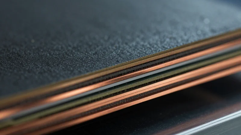
The Rogers 4000 series utilizes a hydrocarbon/ceramic laminate structure specifically engineered to provide stable dielectric constant (Dk) performance over a wide frequency range. Unlike standard FR-4, which exhibits significant Dk drift as temperatures fluctuate, Rogers 4350B and 4003C offer predictable behavior critical for impedance-controlled RF designs. Maintaining precision in line width and spacing during fabrication is paramount to leveraging this stability.
| Material Property | Rogers 4350B | Rogers 4003C |
|---|---|---|
| Dielectric Constant (Dk) @ 10GHz | 3.66 | 3.55 |
| Dissipation Factor (Df) @ 10GHz | 0.0037 | 0.0027 |
| Glass Transition Temp (Tg) | >280°C | >280°C |
Thermal Management and Fabrication Dynamics
Thermal management is a pillar of the Rogers 4000 series value proposition. With a high glass transition temperature (Tg) and a coefficient of thermal expansion (CTE) closely matched to copper, these materials demonstrate exceptional dimensional stability during thermal cycling. However, this rigidity requires specific DFM considerations regarding drill bit selection and desmear processes to prevent PTH (Plated Through Hole) reliability issues during assembly reflow.
Frequently Asked Questions
- Why is the loss tangent (Df) important in these materials?
A lower dissipation factor minimizes signal attenuation, making 4003C and 4350B ideal for high-speed digital and broadband microwave applications where energy loss must be kept at a minimum. - Do I need special storage for Rogers laminates?
While these materials are not moisture-sensitive to the degree of some high-end polyimides, standard industry practice for maintaining strict Dk values recommends storage in a controlled environment to minimize moisture absorption before lamination. - How does the CTE matching impact PCB assembly?
The CTE of the laminate closely matching that of copper ensures that, during extreme thermal loads, the stress on copper plating in barrels is minimized, preventing fatigue cracking and enhancing long-term reliability.
Stack-up Design and Impedance Control
Core and Prepreg Selection Strategies
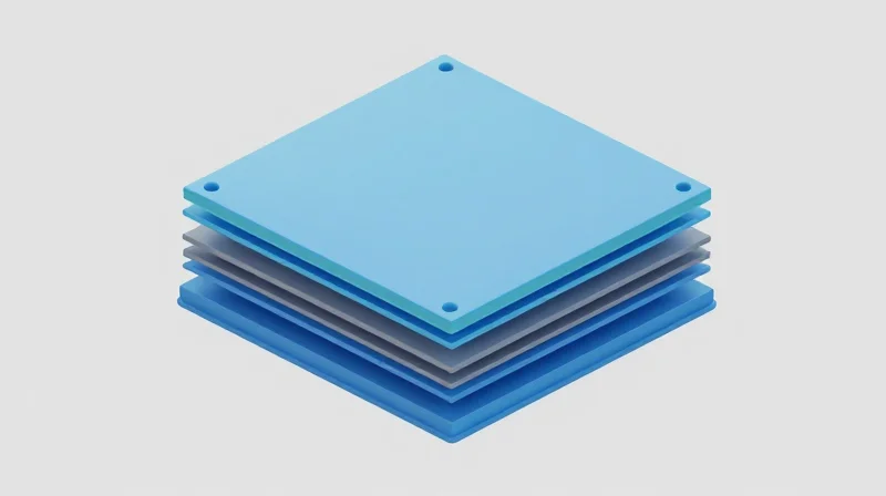
Achieving consistent impedance in high-frequency designs requires a symbiotic relationship between Rogers core thickness and bonding prepreg. Rogers 4350B (Dk 3.66) and 4003C (Dk 3.55) are ceramic-filled glass-reinforced laminates that exhibit significantly lower Z-axis expansion than standard FR-4, making them ideal for high-layer count designs. When selecting dielectric materials, engineers must account for the resin flow of the prepreg, which can slightly shift the effective dielectric constant (Dk) post-lamination. It is recommended to use identical or compatible prepreg glass styles to minimize thermal expansion mismatches and ensure consistent dielectric spacing across the board.
Managing Copper Weights and Surface Roughness
Copper weight directly impacts trace etching profiles and impedance stability. For precision designs, thinner copper foils are preferred to reduce etching undercutting, which is a primary contributor to impedance deviations. Furthermore, the skin effect at higher frequencies means surface roughness of the copper foil significantly influences signal loss. Using low-profile (VLP) or rolled-annealed copper foils is strongly advised to maintain signal integrity.
| Feature | Rogers 4350B | Rogers 4003C |
|---|---|---|
| Dk (@ 10 GHz) | 3.66 | 3.55 |
| Df (@ 10 GHz) | 0.0037 | 0.0027 |
| Primary Application | High-power / Commercial | Low-loss / Aerospace |
Impedance Control FAQ
- How does prepreg flow affect target impedance?
Prepreg resin replaces air gaps between copper features. If the press cycle is not strictly controlled, variations in resin thickness will deviate from the calculated Dk, causing impedance shifts. - What is the impact of copper weight on etching precision?
Heavier copper (e.g., 2 oz) requires longer etch times, which increases trace width side-wall etching, typically resulting in a trapezoidal cross-section that alters calculated impedance. - Why is it important to define stack-ups by finished thickness?
Rogers laminates are sold by weight/core thickness; however, fabrication processes like surface preparation and copper plating change final dimensions. Always provide target impedance based on final copper thickness.
Precision Etching and Trace Width Tolerances

Achieving precise trace geometries on Rogers 4350B and 4003C laminates requires a deep understanding of copper etch factors and the interaction between dielectric constant stability and physical etching processes. Because these materials are frequently used in RF and microwave applications, even minor deviations in trace width due to over-etching or inadequate etch-back control can result in significant impedance mismatch, causing signal attenuation and phase distortion.
Mitigating Etch Factor Effects
The etch factor represents the ratio of the etch depth to the amount of lateral undercutting. For high-frequency Rogers laminates, a high etch factor—achieved through controlled spray pressure and chemistry—is mandatory to produce rectangular trace cross-sections. Trapezoidal traces common in standard FR-4 production are unacceptable here as they alter the effective capacitance and impedance profile along the transmission line.
| Tolerance Target | Requirement for Rogers 4000 | Fabrication Strategy |
|---|---|---|
| Trace Width | +/- 0.5 mil | Advanced laser direct imaging |
| Copper Profile | Rectangular | Controlled etch factor |
| Impedance | +/- 5% | Coupled post-etch verification |
Technical FAQ: Etching and Tolerances
- Why is trace width tolerance more stringent for Rogers 4350B?
These materials are used in high-frequency applications where the skin effect and dielectric constant sensitivity make the trace geometry a primary determinant of impedance; deviations as small as 0.2 mils can shift impedance by several ohms. - How does copper surface roughness impact the etching process?
Rogers 4000 series often utilizes low-profile copper to reduce insertion loss at high frequencies. This smoother copper is more susceptible to aggressive undercutting, necessitating specific etchant chemistry adjustments compared to standard VLP copper. - What is the recommended approach for trace compensation?
Engineers should apply a bias factor to artwork based on the specific copper weight and the manufacturer's known etch rate, ensuring that the final copper geometry matches the design model after the chemical removal process.
Plating Processes and Surface Finish Considerations
Impact of Surface Finishes on High-Frequency Performance
At microwave and millimeter-wave frequencies, the surface finish is not merely a protective layer; it is an extension of the conductor. Surface roughness and conductivity influence the 'skin effect,' where high-frequency currents migrate to the surface of the copper trace. Using finishes with high-loss profiles or excessive surface irregularities can significantly increase insertion loss and introduce unwanted parasitic capacitance.
| Surface Finish | High-Frequency Suitability | Primary Constraint |
|---|---|---|
| ENIG | Moderate | Nickel layer exhibits higher resistive losses at >10GHz. |
| ENEPIG | Good | Higher process complexity and slightly higher cost. |
| Immersion Silver | Excellent | Prone to tarnishing; requires strictly controlled storage. |
| OSP | Excellent | Short shelf life and limited re-workability. |
DFM Considerations for Surface Finish Selection
- Why is ENIG problematic for high-frequency Rogers applications?
The nickel layer in Electroless Nickel Immersion Gold (ENIG) is magnetic and has higher resistivity than copper. At frequencies above 10GHz, this layer contributes to measurable signal attenuation, making it less ideal for precision RF circuits. - Is Immersion Silver recommended for 4350B?
Yes, Immersion Silver is often preferred for high-frequency designs because it maintains a smooth profile and lacks magnetic materials, effectively minimizing insertion loss. However, it requires stringent anti-tarnish handling protocols. - How does surface finish affect trace impedance?
Variations in finish thickness can alter the effective geometry of the trace. When designing for ultra-tight impedance tolerances on 4003C laminates, designers must account for the plating thickness in the final impedance model to avoid mid-production adjustments.
Best Practices for Assembly
To ensure long-term reliability without compromising signal performance, designers should prioritize finishes that provide a flat, uniform surface for high-density interconnects (HDI). When using Rogers 4350B or 4003C, minimize the use of heavy electrolytic plating, which can introduce stress concentrations in the copper foil and induce micro-cracks in the dielectric interface.
Drilling and Via Integrity in RF Boards
Via Geometry and Aspect Ratio Constraints
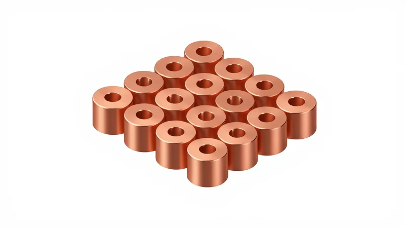
High-frequency performance in Rogers substrates is highly sensitive to via geometry. For 4350B and 4003C materials, maximizing signal integrity requires minimizing the parasitic capacitance and inductance introduced by drilling operations. Maintaining an ideal aspect ratio ensures uniform plating, which is critical for reducing resistance at high frequencies.
| Parameter | Recommended Constraint | Performance Impact |
|---|---|---|
| Max Aspect Ratio | 6:1 or lower | Ensures reliable plating thickness |
| Via Pad Diameter | Drill + 0.20mm | Minimizes parasitic capacitance |
| Anti-pad Clearance | >= 0.30mm | Reduces coupling and reflections |
Back-Drilling for Signal Integrity
At frequencies exceeding 10 GHz, via stubs act as resonant structures that introduce significant signal reflection. Back-drilling (controlled depth drilling) is essential to remove these stubs. For precision fabrication, a residual stub length of less than 0.20mm is recommended to preserve high-speed channel performance.
Fabrication FAQ for High-Speed RF Vias
- Why is drill entry and exit material critical for Rogers 4350B?
The ceramic-filled nature of Rogers laminates can cause drill wander; using high-quality aluminum entry foil and phenolic backup boards prevents burring and ensures perfectly centered holes. - Does plating thickness impact RF signal loss?
Yes, standard plating (25um) is required to minimize skin effect losses; however, excessive plating thickness increases capacitance, which can shift the impedance of the transition. - How does via stitching affect RF design?
Via stitching near RF traces must maintain a minimum distance of 3x the trace width to avoid disruptive field coupling, while maintaining a ground return path as close as possible to the signal transition.
Managing Thermal Expansion and Mechanical Stability
Managing Thermal Expansion in Rogers RF Laminates
Rogers 4350B and 4003C materials feature a low Coefficient of Thermal Expansion (CTE), particularly in the Z-axis, which is critical for plated through-hole (PTH) reliability. However, mismatch between the laminate, copper foil, and bonding materials during reflow cycles can induce significant stress. To minimize this, designers must ensure that the thermal mass is evenly distributed across the board surface and that the stack-up remains balanced relative to the neutral axis.
Design Strategies for Mechanical Stability
| Parameter | Design Rule | Reasoning |
|---|---|---|
| Copper Distribution | Uniform/Symmetrical | Prevents board bowing and twisting during thermal excursions. |
| Layer Stack-up | Symmetric | Ensures uniform CTE distribution across the cross-section. |
| Copper Balancing | Minimum 80% coverage | Reduces uneven resin flow and improves mechanical rigidity. |
Preventing Delamination and Warpage
Delamination is primarily driven by excessive moisture absorption or localized thermal shock. When using Rogers high-frequency laminates, it is imperative to use compatible B-stage prepregs and strictly adhere to pre-drying protocols before the assembly process. Furthermore, oversized copper pours on outer layers should be hatched or cross-hatched if they do not serve a necessary electrical function, as solid large-area copper planes exacerbate stress concentrations.
Common Mechanical Stability Challenges
- Why does asymmetric copper distribution cause warpage?
Asymmetric copper thickness leads to uneven thermal expansion rates across the laminate, causing the PCB to bow toward the side with higher thermal mass during soldering. - Is back-drilling necessary for stability?
While primarily for signal integrity, back-drilling helps maintain uniform board mass and reduces the cumulative CTE impact caused by long via stubs in multi-layer designs. - How does moisture affect Rogers materials?
Despite their low moisture absorption, trapped water can expand rapidly during reflow, leading to internal delamination; always bake boards according to manufacturer guidelines prior to assembly.
Documentation and Fabrication Notes for Manufacturers
Defining Material-Specific Fabrication Requirements
When working with Rogers 4350B or 4003C laminates, standard FR-4 fabrication notes are insufficient. You must explicitly document requirements regarding material loss tangents, dielectric constants (Dk), and moisture absorption sensitivity. Fabrication shops require clear instructions on pre-preg compatibility to ensure the dielectric stack-up maintains the intended impedance targets and minimizes signal attenuation.
Critical Documentation Checklist
- Stack-up Definition
Explicitly define the sequence of cores and pre-preg. Specify the use of compatible bonding materials to ensure the overall Dk is not compromised. - Impedance Tolerances
State strict impedance requirements (+/- 5%) and specify the measurement frequency, as Rogers materials exhibit different characteristics at high GHz ranges. - Drilling and Smear Removal
Request optimized drill parameters for ceramic-filled laminates to prevent burrs and ensure clean via walls. - Surface Finish Specification
Clearly note the desired finish (e.g., ENIG or ENEPIG) and emphasize the need for thickness consistency to minimize resistive losses.
Comparison of Fabrication Handling Considerations
| Parameter | Rogers 4350B/4003C Requirement | Standard FR-4 Approach |
|---|---|---|
| Handling | Clean-room environment/No oil contamination | Standard industrial handling |
| Drill Speed | Reduced feed rates for ceramic fillers | Standard high-speed drilling |
| Bake Cycles | Strict moisture removal pre-lamination | Minimal drying |
| Copper Etch | High-precision compensation for fine lines | Standard allowance |
Communication Best Practices
Ensure your fabrication notes include a 'Manufacturing Data Package' that explicitly references the Rogers datasheet. Avoid generic 'per industry standard' notes; instead, define specific IPC class requirements (e.g., IPC-6012 Class 3). Always provide a 2D drawing that highlights controlled impedance paths, as this allows the fabricator to adjust etch compensation based on the specific board topography.
Mastering the fabrication of Rogers 4350B and 4003C laminates requires a collaborative approach between designer and manufacturer. By adhering to these rigorous DFM standards, you can ensure peak signal performance and long-term reliability for your microwave systems. Contact our engineering team today to review your board stack-up and design for your next high-frequency project.
