
As industrial LED lighting systems push the boundaries of lumen density and longevity, the underlying substrate material has become a critical design decision. With power density increasing and thermal constraints tightening, engineers must navigate the performance gap between legacy FR4 boards and modern high-thermal Aluminum PCBs.
Understanding the Thermal Limitation of FR4
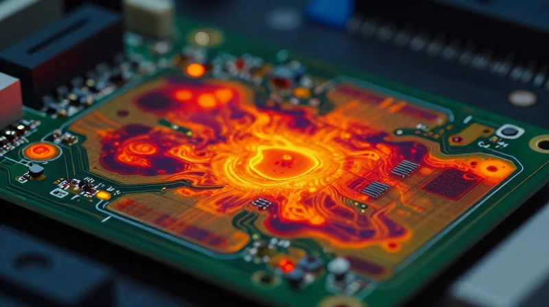
The Thermal bottleneck of FR4
FR4, composed of glass-reinforced epoxy laminate, is the industry standard for general-purpose electronics due to its cost-efficiency and mechanical stability. However, when applied to high-power industrial LED systems, its inherent thermal conductivity—typically ranging between 0.25 W/m·K and 0.35 W/m·K—acts as a severe bottleneck. Unlike metallic substrates, the dielectric resin base of FR4 acts as an insulator, trapping heat generated by LED junctions and leading to rapid thermal degradation, color shifting, and reduced device lifespan.
Why FR4 Struggles with High-Power Heat Dissipation
The primary issue with FR4 in high-lumen density applications is the accumulation of thermal resistance (Rth). As power density increases, the heat generated by the LED die cannot effectively traverse the epoxy layer to reach the ambient air or external heat sink. This results in an increased junction temperature (Tj), which directly correlates to the failure of the luminaire.
| Parameter | FR4 Epoxy Laminate | Impact on High-Power LED |
|---|---|---|
| Thermal Conductivity | 0.25-0.35 W/m·K | Extremely Low (Thermal Insulator) |
| Heat Dissipation Path | Vertical through dielectric | Inefficient; high junction temperature |
| Reliability at High Wattage | Poor (Risk of delamination) | Shortened service life |
Common Challenges with FR4
- Does FR4 work for all LEDs?
No, FR4 is suitable for low-power, low-heat indicators or general lighting, but it is unsuitable for industrial-grade LED arrays exceeding 1-2 watts per unit. - Can thermal vias fix the problem?
While thermal vias can improve heat transfer, they are often insufficient for high-output industrial LEDs and significantly increase the complexity and cost of the PCB fabrication process. - What is the consequence of thermal buildup?
Consistent overheating in FR4 boards leads to the breakdown of the polymer matrix, which can cause board delamination, trace lifting, and catastrophic LED failure.
The Evolution of Aluminum Core PCBs
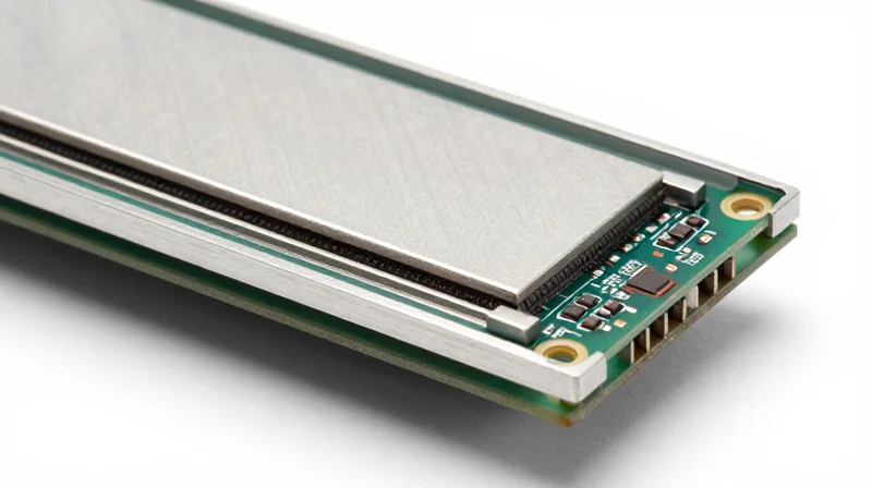
The Anatomy of Thermal Efficiency
The evolution of Aluminum Core Printed Circuit Boards (MCPCBs) represents a fundamental shift from conventional electrical insulation to advanced thermal management. Unlike standard FR4, which utilizes a woven glass-reinforced epoxy that acts as a thermal insulator, Aluminum PCBs feature a dielectric layer sandwiched between a metal base and copper circuitry. This structural transition allows for direct heat dissipation from components through the dielectric interface into the aluminum chassis, bypassing the thermal bottleneck inherent in organic board materials.
Structural Components and Heat Transfer
The effectiveness of an Aluminum PCB relies on three distinct layers: the circuit layer (copper), the dielectric layer (thermally conductive polymer), and the metal base (aluminum alloy). The dielectric layer is the critical component; it must provide high electrical isolation while offering minimal thermal resistance (low Z-axis impedance). As industrial LEDs increase in luminous intensity, the focus has shifted toward high-thermal-conductivity dielectrics that can move heat several times faster than standard epoxy resins.
| Feature | FR4 Substrate | Aluminum Core PCB |
|---|---|---|
| Thermal Conductivity | Low (~0.25 W/mK) | High (1.0 to 5.0+ W/mK) |
| Heat Path | Horizontal spread only | Vertical conduction to base |
| Durability | Prone to delamination | High mechanical stability |
| Thermal Expansion | Higher CTE mismatch | Lower, closer to silicon |
Common Questions on MCPCB Evolution
- Why is the dielectric layer the most critical component?
The dielectric layer acts as a bridge between the heat source and the aluminum sink; its ability to remain electrically insulative while conducting heat determines the total thermal resistance of the assembly. - Does the aluminum base impact mechanical design?
Yes, the metal base provides superior structural rigidity, which is essential for heavy-duty industrial environments where thermal cycling could otherwise cause mechanical fatigue. - Can these boards be used in multilayer designs?
Historically limited to single-layer, modern manufacturing techniques now allow for complex multilayer MCPCBs, though cost remains higher than standard FR4 multi-layer alternatives.
Key Performance Metrics: Conductivity and Dielectric Layers
The Role of the Dielectric Layer in Thermal Resistance
The dielectric layer acts as a paradoxical bridge in Aluminum PCBs; it must provide robust electrical isolation while offering minimal thermal resistance. Unlike the insulating epoxy of standard FR4, the dielectric in a Metal Core Printed Circuit Board (MCPCB) is specifically engineered with thermally conductive fillers—typically ceramic particles like Aluminum Oxide (Al2O3) or Aluminum Nitride (AlN)—to facilitate rapid heat transfer from the junction to the aluminum base. The total thermal resistance is governed by the ratio of the dielectric thickness to its thermal conductivity, meaning that thinner, more conductive layers drastically improve overall heat dissipation efficacy.
| Material Property | Standard FR4 | Typical MCPCB Dielectric |
|---|---|---|
| Thermal Conductivity (W/mK) | 0.25 - 0.35 | 1.0 - 5.0+ |
| Primary Role | Structural Insulation | Thermal Bridge & Isolation |
| Heat Dissipation Path | Lateral (Copper planes) | Vertical (Through dielectric to Al) |
Key Performance Metrics FAQ
- How does dielectric thickness impact system lifespan?
A thinner dielectric layer reduces the thermal path length, lowering the junction temperature of LEDs. Lower operating temperatures directly correlate to reduced degradation of the phosphor layer and increased luminous flux maintenance over time. - Why is thermal conductivity (W/mK) critical for high-power LEDs?
In high-power industrial applications, heat density is extreme. Higher conductivity ratings ensure that heat is moved away from the LED die before it can cause structural mechanical failure or solder joint fatigue, common failure modes in inefficient FR4 systems. - Can I simply use a thinner dielectric to improve performance?
While thinning the layer improves thermal conductivity, it must be balanced against the dielectric breakdown voltage requirement. Engineers must select a layer that satisfies both the dielectric withstand voltage (Hi-Pot) and the thermal dissipation requirements simultaneously.
Longevity and Reliability in Harsh Environments
Thermal Stress and Operational Lifespan
In industrial lighting, the failure of an LED module is almost exclusively linked to the degradation of the junction temperature (Tj). When heat is trapped at the interface, the resultant thermal expansion coefficients (CTE) mismatch causes mechanical stress, leading to delamination, solder joint fatigue, and bond wire failure. By utilizing an aluminum substrate, heat is moved away from the semiconductor die at an accelerated rate, keeping junction temperatures well within the operating limits recommended by manufacturers. This stability is the primary determinant of MTBF in high-intensity environments.
Comparative Reliability Metrics
| Failure Factor | FR4 Performance | Aluminum PCB Performance |
|---|---|---|
| Solder Joint Fatigue | High (Thermal Cycling) | Low (Thermal Stability) |
| Dielectric Breakdown | Moderate | Excellent |
| Expected MTBF | Base Rating | 2x to 5x Base Rating |
Frequently Asked Questions
- How does aluminum specifically impact MTBF?
By maintaining lower junction temperatures, aluminum substrates slow the chemical degradation of the LED phosphor and prevent the brittle fracture of solder joints caused by repeated thermal expansion and contraction. - Can FR4 be used in high-power industrial LED applications?
While possible with extensive copper heat-spreading techniques, FR4 lacks the intrinsic thermal conductivity of aluminum, making it prone to premature failure in environments with high ambient temperatures or continuous 24/7 operation. - Does the dielectric layer affect longevity?
Yes. The dielectric layer in an Aluminum PCB is the critical bottleneck; high-thermal-conductivity dielectrics are essential to ensure the heat moves efficiently into the aluminum core without creating a localized thermal bridge failure.
Sustainability and Life-Cycle Assessments
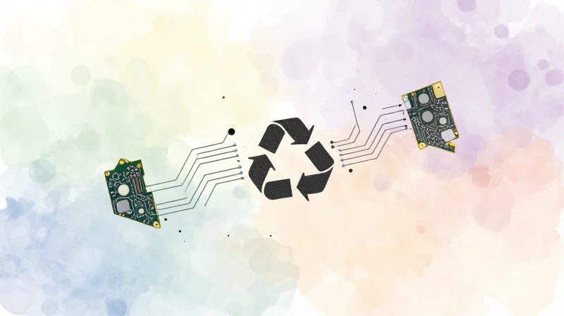
Environmental Footprint and Life-Cycle Analysis
The transition toward sustainable industrial electronics requires a rigorous assessment of materials throughout their life cycle. While FR4 has dominated the market due to its low cost, its disposal often presents significant ecological challenges. In contrast, Aluminum Core Printed Circuit Boards (MCPCBs) offer a superior profile for circular economy models, primarily due to the high recyclability of the aluminum substrate compared to the thermoset resin composite of FR4.
| Feature | Aluminum PCB | FR4 |
|---|---|---|
| Substrate Recyclability | High (Metal reclamation) | Low (Composite incineration/landfill) |
| Material Sourcing | Abundant/Earth-abundant | Fiberglass/Petroleum-based resins |
| Thermal Efficiency Impact | Energy saving through heat dissipation | Thermal bottlenecks increase power load |
| Hazardous Components | Minimal (RoHS compliant) | Brominated flame retardants present |
Sustainability FAQ
- Why is Aluminum PCB considered more 'circular'?
Aluminum is infinitely recyclable without loss of material properties. At the end of the LED module life, the aluminum base can be processed via standard metallurgical recycling streams, whereas FR4 contains complex resins and glass fibers that are difficult to separate and generally end up in hazardous waste or landfill. - Does the thermal management of Aluminum PCBs reduce long-term carbon output?
Yes, by allowing LEDs to run at cooler, more efficient temperatures, Aluminum PCBs prevent the thermal degradation of the diodes. This extends the service life of the luminaire, reducing the frequency of replacement cycles and the overall carbon expenditure of industrial lighting infrastructure. - What are the primary waste management hurdles for FR4?
FR4 boards utilize bromine-based flame retardants to meet fire safety standards. These compounds complicate the recycling process, as they can release toxins if incinerated and are difficult to extract during mechanical recycling.
As environmental regulations like the EU's Circular Economy Action Plan evolve, industrial manufacturers must pivot toward substrates that prioritize reclamation. Future trends indicate that the inherent thermal efficiency of Aluminum PCBs, combined with their post-consumer recyclability, will make them the preferred choice for eco-conscious industrial LED deployments.
Cost-Benefit Analysis for Mass Production
Economic Dynamics of Substrate Selection
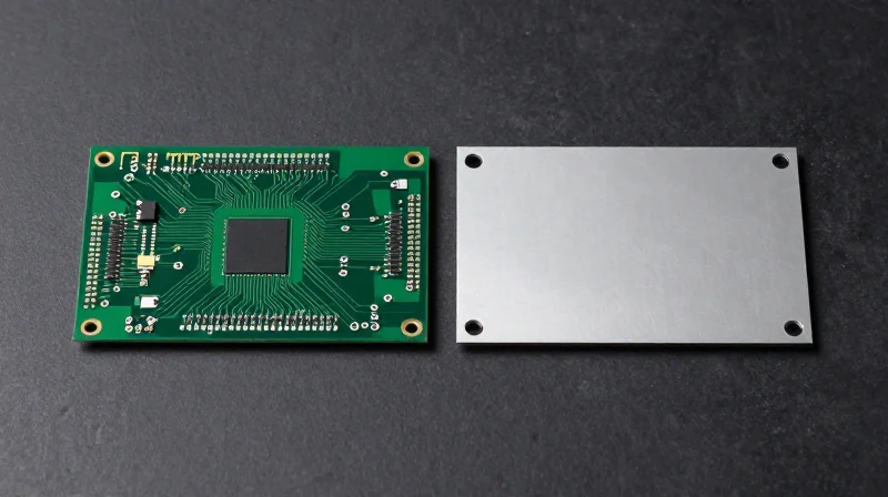
While FR4 remains the industry standard due to its pervasive manufacturing infrastructure and lower base material costs, aluminum PCBs introduce a compelling economic paradox for industrial LED applications. The decision to integrate metal-clad substrates is not merely a material expense but an architectural investment that dictates the total cost of ownership (TCO) through secondary component reduction.
| Cost Metric | FR4 Substrate | Aluminum PCB |
|---|---|---|
| Material Base Cost | Low | Moderate-High |
| Heat Sink Requirements | Complex/Bulky | Simplified/Integrated |
| Assembly Throughput | Standard | Requires Specialized Solder Profiles |
| System TCO | Higher (Due to thermal management) | Lower (Due to extended MTBF) |
Strategic Trade-offs in System Design
The primary economic advantage of aluminum PCBs lies in the consolidation of thermal pathways. By utilizing the metal core as a direct heat spreader, designers can often eliminate bulky, expensive external aluminum extrusions or active cooling systems. This reduction in bill-of-materials (BOM) complexity frequently offsets the initial 15-30% premium paid for metal-based PCB laminates.
Frequently Asked Questions
- Does the higher thermal conductivity of aluminum always justify the cost?
No; it is highly dependent on power density. For low-power indicators, FR4 is sufficient. However, for high-brightness industrial lighting where heat sink costs exceed the PCB material premium, aluminum is almost always more cost-effective. - Are there hidden costs when switching to aluminum substrates?
Yes, manufacturers must account for specialized stencil designs to manage thermal expansion during reflow and potentially higher logistics costs due to the increased weight of aluminum versus fiberglass. - How does PCB choice impact maintenance budgets?
Aluminum PCBs mitigate thermal degradation, which significantly reduces the frequency of field failures. Over a five-year lifecycle, the reduction in maintenance labor and unit replacement costs often makes aluminum the superior financial choice.
Future Projections: Beyond Traditional MCPCBs
Emerging Substrate Alternatives
As thermal density in industrial LED arrays increases, the limitations of standard Aluminum Core PCBs (MCPCB) and FR4 become apparent. Future projections point toward the widespread adoption of Ceramic Matrix Composites (CMC) and Insulated Metal Substrates (IMS) with nanocarbon dielectric layers. These materials offer thermal conductivity coefficients far exceeding traditional aluminum-dielectric stacks while maintaining electrical isolation.
Thermal Management Technology Comparison
| Technology | Thermal Conductivity (W/mK) | Key Advantage |
|---|---|---|
| Standard FR4 | 0.25 | Low cost; mature manufacturing |
| Aluminum MCPCB | 1.0 - 5.0 | Cost-effective heat dissipation |
| Ceramic Substrates | 20.0 - 200+ | High dielectric strength; superior heat flux |
| Nanocarbon Composites | 50.0 - 500+ | Extreme thermal management; lightweight |
Integrated Cooling and Next-Gen Interface Materials
Beyond the PCB itself, the future lies in the integration of micro-channel liquid cooling directly into the substrate architecture. By utilizing additive manufacturing to embed cooling channels, engineers can bypass the bottleneck of traditional Thermal Interface Materials (TIM). Furthermore, phase-change materials and graphene-based thermal pads are replacing traditional silicone greases, offering lower thermal resistance and zero pump-out effect over the product's extended service life.
Frequently Asked Questions
- Will aluminum PCBs become obsolete?
No, aluminum PCBs will remain the standard for mid-to-high power industrial lighting due to their optimal balance of cost and performance; ceramics will be reserved for ultra-high-density applications. - How do nanocarbon materials improve reliability?
Nanocarbon materials reduce the coefficient of thermal expansion (CTE) mismatch between the LED die and the substrate, significantly reducing solder joint fatigue and improving MTBF. - Is active cooling integration necessary for future LEDs?
For high-intensity industrial arrays, integrated micro-fluidics or phase-change solutions are becoming necessary as passive heat dissipation reaches the physical limits of thermal conduction.
Strategic Selection Criteria for Engineers
Critical Selection Framework
Selecting the correct PCB technology is not merely a choice of material, but a fundamental design decision that dictates the lifespan and performance of industrial lighting systems. Engineers must prioritize thermal load capacity over traditional design conventions, as high-power LED arrays often exceed the thermal conductivity thresholds of standard FR4, even when employing copper pours or thermal vias.
| Parameter | FR4 Substrate | Aluminum MCPCB |
|---|---|---|
| Thermal Conductivity | Low (~0.25 W/mK) | High (1.0 to 3.0+ W/mK) |
| Power Density | Low to Medium | High to Extreme |
| Mechanical Rigidity | Flexible/Standard | High (Non-bending) |
| Heat Sink Integration | External Required | Integrated Base |
Decision Matrix for Engineering Teams
- Thermal Load Assessment
If your application involves LED densities exceeding 1.5W per square inch, Aluminum MCPCBs are generally required to prevent dielectric breakdown and junction temperature degradation. - Mechanical Durability
For industrial environments prone to vibration or physical impact, the metal base provides superior structural integrity compared to the multi-layer fiberglass construction of FR4. - Assembly Cost Optimization
While FR4 is cheaper per unit, the total cost of ownership (TCO) often favors Aluminum PCBs because they eliminate the need for expensive secondary heat sinks and complex thermal interface material (TIM) assembly steps. - Circuit Complexity
FR4 remains the standard for high-density, multi-layer routing. If the design requires complex control logic or high-frequency communication traces, a hybrid approach or copper-core FR4 may be necessary.
Ultimately, the strategic transition from FR4 to Aluminum substrates in industrial LED manufacturing is driven by the necessity for smaller form factors and increased lumen output. Engineers must evaluate the thermal path resistance from the LED junction to the aluminum base, ensuring that the dielectric layer thickness is optimized for both voltage isolation and heat transfer efficiency.
Transitioning to Aluminum PCB technology is no longer just an upgrade—it is a competitive necessity for high-performance industrial lighting. By prioritizing thermal management today, your products will achieve superior reliability and market longevity. Contact our engineering team to discuss how your next project can benefit from optimized substrate selection.
