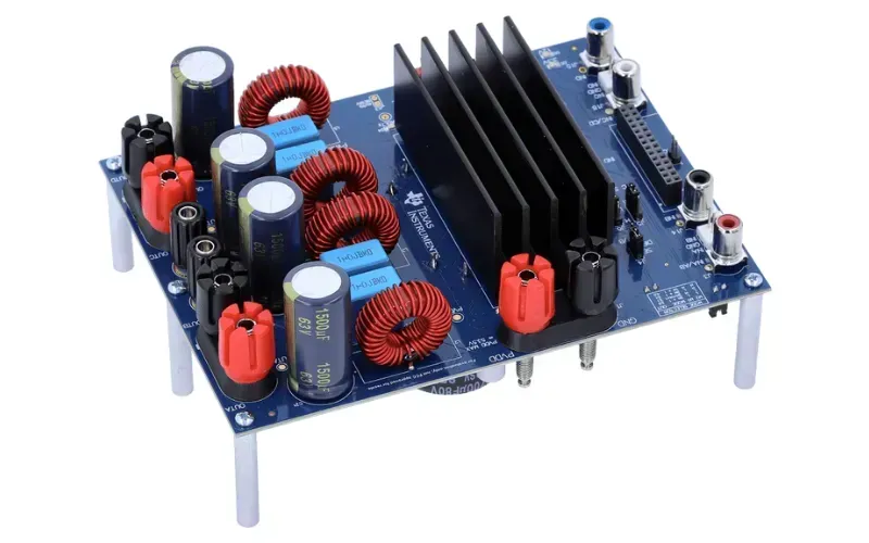
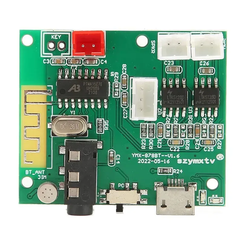
In the realm of audio technology, the quality of sound processing is paramount. Whether it's a high-end amplifier, a sophisticated mixing console, or a noise-canceling headphone, the heart of these devices lies in their audio processor PCB (Printed Circuit Board). A well-designed audio processor PCB ensures signal integrity, minimizes noise, and optimizes performance. As a leading PCB solution provider, Zero One Solution Limited empowers audio innovation through cutting-edge PCB design, manufacturing, and assembly. How can a superior audio processor PCB elevate your audio product's performance and market competitiveness? This article delves into the world of audio processor PCB solutions, exploring design considerations, manufacturing processes, and the critical role they play in achieving exceptional audio quality.
Understanding the Audio Processor PCB Ecosystem
Audio Processor PCB Components
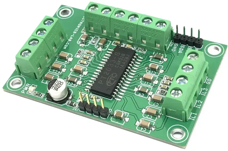
At the heart of superior audio performance lies a meticulously engineered Audio Processor PCB. This complex ecosystem integrates a diverse array of electronic components, each playing a crucial role in transforming raw audio signals into rich, clear sound. From managing intricate signal paths to mitigating noise, the design and functionality of these fundamental elements are paramount to achieving unparalleled audio fidelity, making them the cornerstone of any high-quality audio device.
Digital Signal Processors (DSPs) DSPs are the brains of the audio processor PCB, executing complex algorithms for filtering, equalization, compression, and other effects. They handle the conversion of analog audio to digital, and vice versa, often operating at high clock speeds and requiring careful power management and signal integrity considerations to prevent digital noise from contaminating analog sections. Leading manufacturers include Analog Devices, Texas Instruments, and Cirrus Logic, with specific models optimized for low power, high resolution, or multi-channel processing.
Audio Codecs (CODECs) Audio CODECs (Coder-Decoder) are integrated circuits that convert analog audio signals into digital data and vice versa. They are critical for handling audio input (microphones) and output (speakers/headphones) in a digital system, combining analog-to-digital converters (ADCs) and digital-to-analog converters (DACs) into a single chip. High-performance CODECs often feature advanced noise reduction, anti-aliasing filters, and support for various sampling rates and bit depths to maintain audio fidelity. Examples include CS4398 from Cirrus Logic and WM8741 from Wolfson Microelectronics.
Power Management Integrated Circuits (PMICs) Clean and stable power is essential for high-fidelity audio. PMICs regulate and distribute power efficiently to various components on the PCB, minimizing ripple and noise that could degrade audio quality. This includes low-dropout (LDO) regulators, switching regulators, and voltage references. Proper PMIC selection and layout are critical to isolate sensitive analog audio paths from noisy digital power rails. Linear Technology and Texas Instruments offer a wide range of PMICs suitable for audio applications.
Analog-to-Digital Converters (ADCs) & Digital-to-Analog Converters (DACs) While often integrated into CODECs or DSPs, standalone ADCs and DACs are used in high-end audio systems for their specialized performance. ADCs convert continuous analog audio signals into discrete digital representations, while DACs perform the inverse, converting digital data back into analog waveforms. The quality of these conversions, determined by factors like bit depth, sampling rate, and signal-to-noise ratio (SNR), directly impacts the audio system's clarity and dynamic range. High-resolution ADCs/DACs from manufacturers like AKM Semiconductor and ESS Technology are commonly found in professional audio equipment.
Passive Components (Resistors, Capacitors, Inductors) These foundational components are crucial for filtering, coupling, and impedance matching within the audio signal path. Low-noise resistors, high-quality film capacitors (for audio coupling and filtering), and low-ESR (Equivalent Series Resistance) electrolytic capacitors (for power supply filtering) are selected to minimize distortion and noise. Inductors are used in power filtering and sometimes in speaker crossovers. The choice and placement of these components significantly influence the overall audio performance, especially in sensitive analog sections.
Key Design Considerations for Audio PCBs
Designing high-performance audio processor PCBs demands meticulous attention to specific considerations that directly impact sound quality, noise reduction, and overall system stability. Unlike general-purpose PCBs, audio applications are highly sensitive to electromagnetic interference (EMI), power supply ripple, and signal integrity issues, making careful design paramount to achieving pristine audio reproduction. Optimizing factors such as signal routing, robust grounding schemes, precise power supply filtering, and controlled impedance ensures the faithful transmission and processing of delicate audio signals, preventing distortion and preserving dynamic range.
Design Consideration
Description
Impact on Audio Performance
Signal Routing
Minimize trace lengths, avoid sharp bends, and maintain appropriate spacing between traces. Isolate analog and digital signals to prevent cross-talk and interference.
Reduces signal degradation, minimizes noise pickup, and preserves audio fidelity and clarity by maintaining signal integrity.
Grounding Techniques
Implement a star grounding scheme with a single-point ground reference for analog signals. Use separate ground planes for analog and digital sections, connected at a common point.
Eliminates ground loops, reduces common-mode noise, and prevents hum or buzz, leading to a lower noise floor and improved dynamic range.
Power Supply Filtering
Employ multi-stage filtering (e.g., LC filters, low-ESR capacitors) close to sensitive components. Use linear regulators for critical analog stages where noise sensitivity is high.
Suppresses power supply ripple and noise, preventing it from coupling into audio signals and causing unwanted harmonics or background noise. Ensures clean power for sensitive circuits, crucial for high fidelity audio.
Impedance Control
Match trace impedances to transmission line requirements, especially for high-frequency digital audio or sensitive analog paths. Use impedance-controlled routing for critical signal paths.
Minimizes signal reflections and ensures maximum power transfer, preventing signal loss and distortion, particularly important for high-speed digital audio interfaces and sensitive analog inputs/outputs.
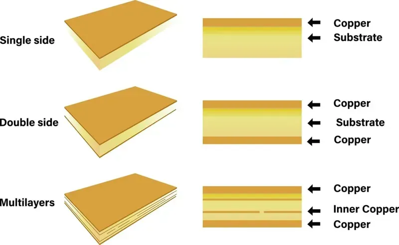
Material Selection for Optimal Audio Performance
PCB Material Samples
The foundation of superior audio performance in any audio processor PCB solution lies profoundly in the judicious selection of PCB materials. Beyond merely serving as a substrate for components, the dielectric properties, thermal characteristics, and mechanical stability of the chosen material directly influence signal integrity, minimize loss, and ultimately define the clarity and fidelity of the audio output. While standard FR-4 remains a common choice for its cost-effectiveness, high-performance audio applications demand a deeper understanding of advanced laminates like Rogers, which offer specific advantages in dielectric constant stability and lower dissipation factors, crucial for preserving signal purity at higher frequencies and reducing harmonic distortion.
General audio processing, Consumer electronics, Cost-sensitive designs
Cost-effective, Widely available, Easy to process
Higher signal loss at high frequencies, Less stable Er, Susceptible to moisture absorption
High-Tg FR-4
Higher glass transition temperature (>170°C), Improved thermal stability
High-power audio amplifiers, Automotive audio
Better thermal performance, Increased reliability in harsh environments
Slightly higher cost than standard FR-4
Rogers (e.g., RO4000 series)
Lower Er (~2.2-3.5), Very low Df (0.002-0.004), Excellent dimensional stability
High-fidelity audio, RF/microwave audio, Professional audio equipment, High-speed digital audio interfaces
Superior signal integrity, Minimal signal loss, Excellent phase stability, Consistent performance across frequencies
Higher cost, More challenging to process (drilling, lamination)
Teflon (PTFE) based
Extremely low Er (~2.1), Very low Df (<0.001), Excellent chemical resistance
Ultra high-end audio, High-frequency audio test equipment
Exceptional signal purity, Near-perfect impedance control
Very high cost, Difficult to process, Poor mechanical stability
Optimizing audio performance through material selection goes beyond simply choosing a low-loss material; it involves a holistic approach considering the entire signal chain, operating frequencies, thermal management needs, and cost constraints. For high-fidelity and professional audio applications, investing in materials with stable dielectric properties and low dissipation factors, even if more expensive, translates directly into a more accurate and transparent audio reproduction. Zero One Solution Limited leverages its extensive experience with diverse PCB materials, guiding clients to make informed decisions that balance performance, reliability, and budget for their specific audio processor PCB solutions.
Advanced PCB Layout Techniques for Audio Signal Processing
PCB Star Grounding Layout
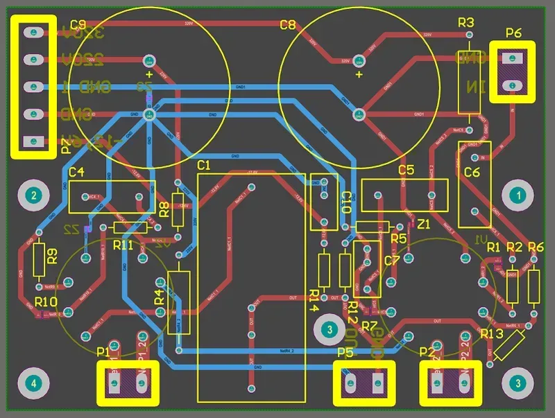
Achieving pristine audio output from an audio processor PCB hinges critically on advanced layout techniques that meticulously mitigate interference and ensure signal integrity. Beyond basic routing, these strategies are fundamental to preserving the delicate nuances of audio signals, preventing noise induction, and delivering the high-fidelity sound that demanding audio applications require. Engineers must employ a disciplined approach, integrating sophisticated design principles from the outset to avoid costly revisions and performance compromises.
Star Grounding Topology Star grounding is a superior method for audio PCBs, where all ground connections converge at a single, central point. This prevents ground loops and minimizes common-mode noise, crucial for sensitive analog audio paths. It ensures that ground currents from different sections (e.g., analog, digital, power) do not interfere with each other, maintaining a stable ground reference for all components.
Differential Signaling Implementation For critical audio paths, differential signaling offers robust noise immunity. By transmitting the signal and its inverted counterpart, any noise picked up equally by both traces is effectively canceled out at the receiver. This technique is particularly valuable for long traces or environments prone to electromagnetic interference, ensuring a clean signal transmission.
Effective Shielding Strategies Proper shielding, including ground planes and Faraday cages, is vital to protect sensitive audio signals from external electromagnetic interference (EMI) and prevent internal signal radiation. A solid ground plane beneath signal traces provides a low-impedance return path and acts as a shield, while targeted component shielding can further isolate critical areas, preserving signal purity.
Controlled Impedance Routing Maintaining controlled impedance for high-speed digital audio signals (e.g., I2S, SPDIF) prevents reflections and signal degradation. By matching the trace impedance to the characteristic impedance of the transmission line, signal integrity is preserved, ensuring accurate data transfer and preventing jitter that can negatively impact audio quality.
Strategic Component Placement for Isolation The physical separation and strategic placement of analog, digital, and power sections on the PCB are paramount. Analog and digital circuits should be isolated with appropriate spacing and, where necessary, separate ground planes connected at a single point (star ground). This minimizes cross-talk and mutual interference, which are common sources of noise in mixed-signal audio designs.
Manufacturing Process and Quality Control in Audio PCB Production
PCB Manufacturing Process
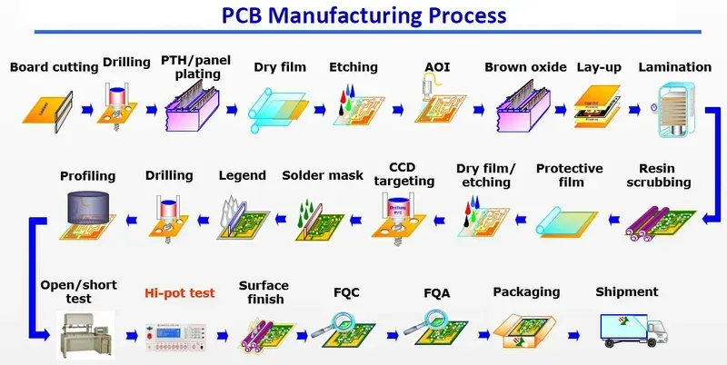
The journey of an audio processor PCB from design to a high-performance component demands an exacting manufacturing process underpinned by stringent quality control. Precision at every stage, from material selection and fabrication to component placement and soldering, is paramount to achieving the pristine signal integrity and low noise floors essential for superior audio reproduction. Any deviation can introduce unwanted artifacts, underscoring the critical role of robust quality assurance protocols throughout the production lifecycle.
PCB Fabrication This initial phase involves creating the bare PCB substrate according to the design specifications. Key steps include cutting the laminate, drilling precise holes for vias and component leads, applying copper traces through photolithography and etching, and finally, applying solder mask and silkscreen layers. For audio applications, maintaining tight impedance control and precise trace geometries is critical to prevent signal degradation and maintain consistent audio characteristics.
Component Procurement and Preparation Sourcing high-quality, authentic components is crucial. This step involves meticulous verification of component specifications, often including passive components with tight tolerances and specialized audio ICs. Proper storage and handling, including moisture sensitivity level (MSL) control for integrated circuits, are vital to prevent damage and ensure optimal performance during assembly.
Automated SMT Assembly (SMT) Surface Mount Technology (SMT) is the primary method for placing components. This involves applying solder paste using stencils, followed by precise component placement by pick-and-place machines, and then reflow soldering. For audio PCBs, precise control of the reflow profile is essential to ensure strong, reliable solder joints without damaging sensitive audio components or introducing thermal stress that could affect long-term performance.
Through-Hole Component Assembly (THT) For components not suitable for SMT, such as larger connectors or certain electrolytic capacitors, through-hole technology is used. Components are inserted into pre-drilled holes and then soldered, often using wave soldering or selective soldering. Care must be taken to manage thermal exposure and ensure robust connections.
Washing and Cleaning After soldering, PCBs are typically cleaned to remove flux residues and other contaminants that could lead to electrical shorts, corrosion, or signal interference. For high-fidelity audio circuits, the cleanliness of the board is particularly important to prevent noise and leakage currents that could impact audio performance.
Testing and Inspection Rigorous testing is indispensable. This includes Automated Optical Inspection (AOI) for solder joint quality and component presence, X-ray inspection for hidden solder joints (like BGAs), In-Circuit Testing (ICT) for component values and connectivity, and functional testing to verify the complete audio processing chain. For audio PCBs, specific acoustic and electrical performance tests (e.g., THD+N, SNR, frequency response) are critical to confirm the board meets its performance targets. Environmental stress screening (ESS) may also be employed to identify potential weaknesses.
Final Quality Assurance Before packaging, a final visual inspection and often a sample-based functional test are conducted. This ensures that the aesthetic quality, labeling, and overall integrity of the PCB meet specifications, providing an additional layer of confidence in the delivered product.
At Zero One Solution Limited, our manufacturing facilities adhere to IPC standards and employ advanced process control methodologies to guarantee that every audio processor PCB we produce delivers uncompromising sound quality and reliability.
Rapid Prototyping for Audio Processor PCB Development
Audio PCB Prototype
Rapid prototyping is a cornerstone in the agile development of Audio Processor PCBs, enabling engineers to quickly transform theoretical designs into tangible prototypes for iterative testing and validation. This expedited process is critical for audio applications where subtle design nuances can significantly impact performance, allowing for rapid identification and rectification of issues like noise, distortion, or signal integrity problems before committing to mass production. It dramatically reduces development cycles, minimizes costly rework, and ultimately accelerates time-to-market for innovative audio products.
Accelerated Design Iteration Rapid prototyping allows for multiple design iterations in a fraction of the time compared to traditional methods. This is crucial for audio PCBs where fine-tuning component placement, trace routing, and grounding schemes are essential for achieving optimal acoustic performance and mitigating electromagnetic interference (EMI).
Early Performance Validation By quickly producing functional prototypes, engineers can conduct real-world performance tests much earlier in the development cycle. This includes analyzing signal-to-noise ratios, total harmonic distortion, and frequency response, identifying potential issues that simulation alone might miss, and ensuring the audio quality meets stringent specifications.
Cost Efficiency in Development While there is an initial investment in rapid prototyping capabilities, the overall cost savings come from reducing the number of costly redesigns and re-spins of production PCBs. Identifying and correcting errors in the prototype phase is significantly cheaper than rectifying them after mass manufacturing has commenced. This is particularly beneficial for complex audio processor PCBs where even minor errors can lead to expensive recalls or product failures.
The Role of Signal Integrity in Audio PCB Design
Signal integrity (SI) is paramount in audio PCB design, acting as the bedrock for faithful audio reproduction. Any degradation in signal quality, even subtle, can introduce unwanted noise, distortion, or crosstalk, compromising the acoustic experience. High-fidelity audio demands meticulous attention to SI, ensuring that the electrical signals representing audio waves traverse the PCB traces without alteration or loss, preserving the nuances and clarity of the original sound. This critical consideration underpins the entire design process, from component selection to layout strategies, directly impacting the final product's audio performance.
SI Challenge
Impact on Audio Performance
Mitigation Strategy
Impedance Mismatch
Signal reflections, ringing, and distortion.
Controlled impedance routing, termination networks, and precise trace width/spacing calculations.
Crosstalk
Unwanted signal coupling between adjacent traces, leading to noise.
Adequate trace spacing, differential routing, and ground planes.
Ground Bounce
Voltage fluctuations in the ground reference, causing noise and data errors.
Solid ground planes, multiple ground vias, and proper power distribution network (PDN) design.
Why is signal integrity crucial for audio PCBs? Signal integrity ensures that the delicate analog audio signals are transmitted across the PCB without degradation, preserving the original waveform's fidelity. Any signal distortion, reflections, or noise introduced by poor SI can lead to audible artifacts, reduced dynamic range, and overall diminished audio quality, which is unacceptable in high-performance audio systems. Maintaining high SI is fundamental to achieving transparent and accurate audio reproduction from the source to the output.
import numpy as np
import matplotlib.pyplot as plt

def simulate_transmission_line(input_signal, Z0, ZL, L, C, R=0, G=0, num_sections=100, dt=1e-10, total_time=1e-7):
    # Simplified transmission line simulation for conceptual understanding
    # This is a basic model and does not cover all SI complexities

    dx = L / num_sections
    dz = Z0 / dx # Impedance per unit length

    voltage = np.zeros((num_sections + 1, int(total_time / dt)))
    current = np.zeros((num_sections + 1, int(total_time / dt)))

    # Apply input signal at the source
    voltage[0, :] = input_signal

    for t_idx in range(1, int(total_time / dt)):
        for x_idx in range(num_sections):
            dV_dt = -(current[x_idx, t_idx-1] - current[x_idx+1, t_idx-1]) / C
            dI_dt = -(voltage[x_idx, t_idx-1] - voltage[x_idx+1, t_idx-1]) / L

            voltage[x_idx+1, t_idx] = voltage[x_idx+1, t_idx-1] + dV_dt * dt
            current[x_idx+1, t_idx] = current[x_idx+1, t_idx-1] + dI_dt * dt

    # Simplified reflection at load for demonstration
    reflection_coefficient = (ZL - Z0) / (ZL + Z0)
    reflected_voltage = voltage[-1, :] * reflection_coefficient

    # This simulation is highly simplified and meant for conceptual visualization
    # Real SI analysis involves complex solvers and S-parameters

    return voltage[-1, :] + reflected_voltage # Return output at load + simplified reflection

# Example usage:
# time = np.linspace(0, 1e-7, int(1e-7 / 1e-10))
# input_pulse = np.where((time > 1e-8) & (time < 2e-8), 1.0, 0.0)

# Z0_line = 50  # Characteristic impedance
# ZL_load_matched = 50 # Matched load
# ZL_load_mismatched = 100 # Mismatched load

# L_line = 1e-7 # Inductance of the line
# C_line = 1e-12 # Capacitance of the line

# output_matched = simulate_transmission_line(input_pulse, Z0_line, ZL_load_matched, L_line, C_line)
# output_mismatched = simulate_transmission_line(input_pulse, Z0_line, ZL_load_mismatched, L_line, C_line)

# plt.plot(time, input_pulse, label='Input Signal')
# plt.plot(time, output_matched, label='Output (Matched Load)')
# plt.plot(time, output_mismatched, label='Output (Mismatched Load)')
# plt.legend()
# plt.title('Simplified Signal Integrity Simulation (Conceptual)')
# plt.xlabel('Time (s)')
# plt.ylabel('Voltage')
# plt.grid(True)
# plt.show()
Case Studies: Successful Audio Processor PCB Implementations
Audio Product PCB
Real-world applications of Audio Processor PCB Solutions offer invaluable insights into how meticulous design and manufacturing translate into superior audio performance. These case studies underscore the critical role of advanced PCB engineering in overcoming challenges such as noise, distortion, and signal integrity issues, ultimately delivering an immersive and high-fidelity sound experience. By examining these implementations, engineers can glean practical strategies for their own projects.
High-End Studio Monitor Speakers **Challenge:** Achieving ultra-low noise floors and minimal distortion across a wide frequency range for professional audio monitoring. This demanded exceptional signal-to-noise ratio (SNR) and total harmonic distortion (THD) characteristics. **Solution:** Employed multi-layer PCBs with optimized ground planes and isolated analog/digital sections. Differential signaling for critical audio paths and careful component placement, including specialized low-ESR capacitors, were instrumental in minimizing interference. The power delivery network was meticulously designed with multiple stages of filtering and regulation to ensure pristine power rails for sensitive audio ICs. Zero One Solution Limited's rapid prototyping capabilities enabled quick iterations and validation of different grounding schemes and power supply filtering options.
Automotive Infotainment Systems **Challenge:** Integrating a powerful audio processor into a highly electromagnetically noisy environment (vehicle chassis) while maintaining audio fidelity and managing thermal dissipation in confined spaces. **Solution:** Utilized robust PCB materials with excellent thermal conductivity and incorporated comprehensive EMI shielding. Strategic placement of audio components away from high-current power traces and RF modules, along with dedicated power and ground planes for audio circuits, effectively mitigated noise. Advanced thermal management solutions, including thermal vias and heatsinks directly integrated into the PCB layout, ensured reliable operation under varying temperature conditions. Our expertise in designing for harsh environments was crucial here.
Professional Live Sound Mixers **Challenge:** Handling a multitude of analog and digital audio inputs and outputs with precise timing and minimal crosstalk, often in a compact form factor. The focus was on maintaining high channel separation and dynamic range. **Solution:** Implemented highly optimized routing for hundreds of audio traces, utilizing impedance-controlled differential pairs for analog signals and high-speed digital buses. Strategic use of ground stitching vias and guard rings around sensitive analog sections prevented signal degradation and crosstalk. The design incorporated robust connectors and strain relief for frequent plugging and unplugging in demanding live environments. Zero One Solution Limited's precision manufacturing ensured the tight tolerances required for complex multi-layer designs.
Wearable Audio Devices (True Wireless Earbuds) **Challenge:** Miniaturization and power efficiency were paramount, along with maintaining high audio quality in a very small footprint. Integration of Bluetooth modules and battery management systems added complexity. **Solution:** Employed high-density interconnect (HDI) PCBs with micro-vias and fine-pitch component placement to achieve extreme miniaturization. Low-power audio codecs and amplifiers were selected, and the PCB was designed to minimize power consumption through efficient trace routing and optimized power plane design. Careful antenna placement and isolation techniques were used to prevent interference between the audio circuitry and wireless communication. Zero One Solution Limited's advanced assembly capabilities were essential for handling the tiny components and complex stacked designs.
Zero One Solution Limited: Your Partner for Audio Processor PCB Solutions
Zero One Solution Limited stands as a premier partner for advanced audio processor PCB solutions, leveraging over a decade of specialized experience in rapid prototyping, design, manufacturing, and assembly. Our comprehensive approach ensures that every audio PCB we deliver meets the highest standards of signal integrity, acoustic fidelity, and reliability, crucial for cutting-edge audio applications. We understand the unique challenges of audio electronics and are dedicated to empowering innovators to bring their sonic visions to life with unparalleled efficiency and precision.
Rapid Prototyping for Accelerated Development Our rapid prototyping services are engineered to significantly compress your development cycles. By providing quick-turn PCB fabrication and assembly, we enable iterative design refinement and swift validation of your audio processor concepts, translating directly into faster time-to-market for your products. This agile approach minimizes risks and optimizes resource allocation during critical R&D phases, ensuring your audio innovations are ready for deployment when it matters most.
Service Area
Key Benefit for Audio PCBs
Zero One Solution Limited Advantage
PCB Design Optimization
Minimized noise and distortion, enhanced signal integrity
Expertise in critical audio layout techniques (e.g., star grounding, differential pairs)
High-Performance Material Sourcing
Superior acoustic performance, reduced dielectric loss
Access to advanced laminates (e.g., Rogers) for demanding audio applications
Precision Manufacturing & Assembly
Consistent performance, high reliability
Rigorous quality control, advanced SMT and through-hole capabilities
Comprehensive Testing & Validation
Guaranteed functionality and performance
State-of-the-art testing equipment, adherence to industry standards
Partner with Zero One Solution Limited to transform your audio concepts into reality. Our commitment to excellence, combined with our global supply chain network and strategic locations in Shenzhen and Dubai, positions us as the ideal partner for high-performance audio processor PCB solutions that resonate with quality and innovation.
FAQ: Audio Processor PCB Design and Manufacturing
Navigating the complexities of Audio Processor PCB design and manufacturing often leads to common questions regarding performance, reliability, and optimization. This section addresses frequently asked questions, offering precise and insightful answers to guide engineers and designers in achieving superior audio quality and robust circuit board functionality.
What are the primary challenges in designing a high-fidelity audio processor PCB? The main challenges include mitigating noise and electromagnetic interference (EMI), ensuring signal integrity across wide frequency ranges, managing thermal dissipation for sensitive components, and implementing effective grounding schemes to prevent ground loops. Achieving low total harmonic distortion (THD) and a high signal-to-noise ratio (SNR) is paramount, necessitating meticulous component selection and layout.
How does material selection impact the performance of an audio PCB? PCB material (substrate) significantly affects signal propagation speed, impedance control, and dielectric losses. For audio applications, materials with low dissipation factors (Df) and stable dielectric constants (Dk) are preferred to minimize signal degradation, especially at higher frequencies. FR-4 is common, but specialized laminates like those from Rogers are utilized for ultra-high-fidelity or RF-sensitive audio paths due to their superior electrical properties.
What are best practices for grounding in audio processor PCB layouts? Optimal grounding is crucial to prevent noise coupling. Best practices include employing a "star ground" configuration where all grounds connect to a single point, separating analog and digital grounds with a single-point connection, using wide ground planes to minimize impedance, and ensuring low-inductance ground return paths for high-frequency signals. This minimizes common-mode noise and ground loops.
Why is thermal management important for audio processor PCBs? Audio processor ICs, especially power amplifiers and high-speed digital processors, generate significant heat. Excessive temperature can degrade component performance, reduce lifespan, and introduce thermal noise. Effective thermal management, through proper heatsinking, thermal vias, and careful component placement, ensures stable operation, consistent audio quality, and long-term reliability.
How does Zero One Solution Limited ensure quality in audio PCB manufacturing? Zero One Solution Limited employs a multi-faceted approach to quality assurance for audio PCBs. This includes stringent DFM (Design for Manufacturability) analysis, precise automated optical inspection (AOI) and X-ray inspection for component placement and solder joint integrity, in-circuit testing (ICT) for electrical functionality, and functional testing to verify audio performance parameters. We adhere to IPC standards and implement rigorous quality control throughout the entire manufacturing and assembly process to meet the demanding requirements of audio applications.
In conclusion, the audio processor PCB is a cornerstone of high-quality audio devices. Zero One Solution Limited provides comprehensive PCB solutions, from design and rapid prototyping to manufacturing and assembly, ensuring optimal performance and signal integrity for your audio products. By partnering with us, you gain access to expertise, cutting-edge technology, and a commitment to excellence. Elevate your audio processing capabilities and unlock new levels of audio fidelity with Zero One Solution Limited. Contact us today to discuss your audio PCB project and discover how we can help you achieve superior sound quality. Share this article to help other engineers and designers understand the importance of a well-designed audio processor PCB!