In the intricate world of electronics, the BC547 transistor stands out as a fundamental component, much like a key character in a story. This NPN bipolar junction transistor, often found in everyday circuits and electronic devices, serves as a cornerstone for amplification and switching. We'll unravel its working, applications, and equivalents, making its functionalities accessible and clear. This journey will make you understand the significant roles that the BC547 plays, from simple signal amplifiers to complex electronic gadgets, and bring some practical usage of this versatile transistor.
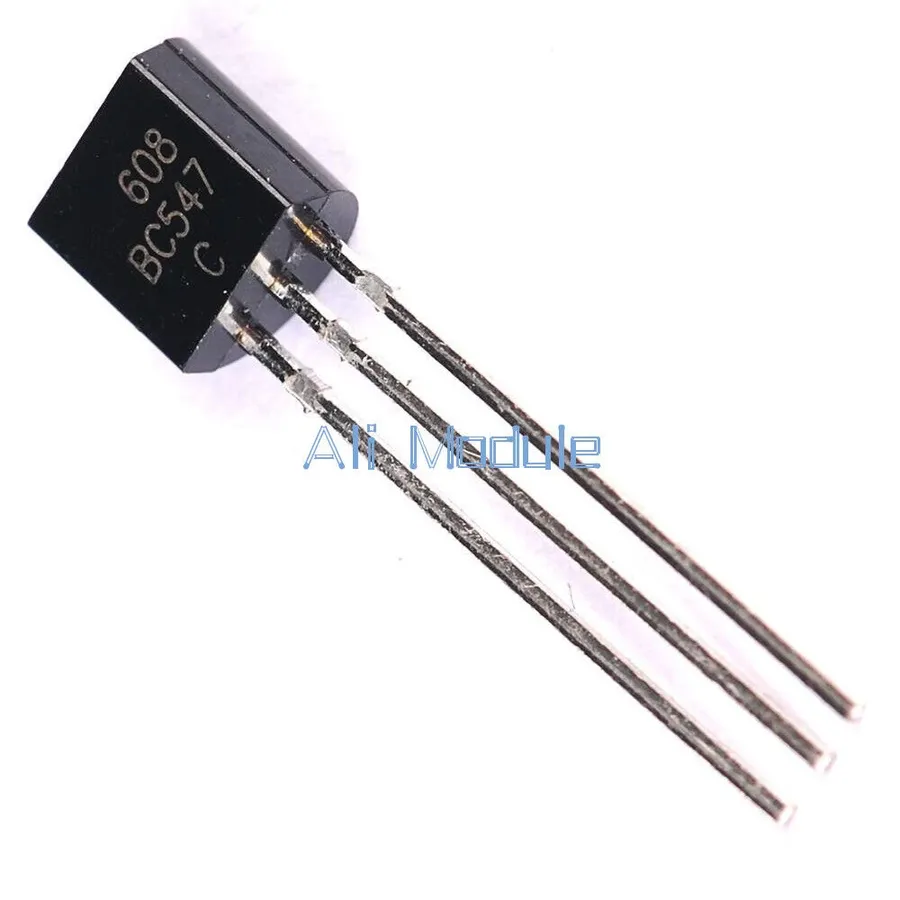
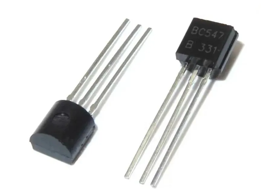
The BC547 is a fundamental NPN bipolar junction transistor (BJT) renowned for its versatility and widespread use in electronics. As a cornerstone component, it primarily functions as an amplifier or an electronic switch, facilitating signal amplification and enabling the controlled activation or deactivation of circuits.
Its design and construction make it suitable for a broad range of applications, from basic switching mechanisms to more complex amplification tasks in both analog and digital circuits. The BC547's importance is derived from its reliability, cost-effectiveness, and ease of integration, making it a go-to choice for engineers, hobbyists, and educational purposes.
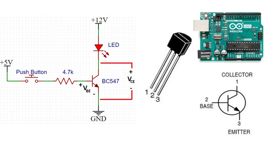
The BC547 is a three-terminal NPN bipolar junction transistor (BJT), with each terminal playing a distinct role in its operation. These terminals are the base (B), collector (C), and emitter (E), and understanding their functionality is crucial for effective circuit design and implementation. The transistor's behavior is governed by the interactions between these terminals, facilitating both signal amplification and switching actions within electronic circuits.
| Pin | Name | Function |
|---|---|---|
| 1 | Collector (C) | Collects current; this is typically where the load is connected in switching applications and is the output in an amplifier configuration. It is more positive than the emitter. |
| 2 | Base (B) | Controls the current flow between the collector and emitter. A small current applied to this terminal can control a larger current flowing through the transistor. |
| 3 | Emitter (E) | Emits current; usually connected to ground in common-emitter configuration. Electrons flow into the collector from this terminal. |
The BC547 transistor's performance is defined by several key electrical characteristics, crucial for effective circuit design. Understanding these parameters, such as DC current gain (hFE), collector current (IC), base-emitter voltage (VBE), and collector-emitter voltage (VCE), allows engineers to optimize its use in varied applications. These values dictate how the transistor will behave under different operating conditions, and are essential for reliable circuit operation.
| Parameter | Symbol | Typical Value | Unit | Description |
|---|---|---|---|---|
| DC Current Gain | hFE | 110-800 (varies by variant) | - | Ratio of collector current to base current; indicates the transistor's amplification capability. |
| Collector Current | IC | 100 | mA | Maximum current the transistor can handle through its collector without damage. |
| Base-Emitter Voltage | VBE | 0.7 | V | Forward voltage required to turn the transistor on. |
| Collector-Emitter Voltage | VCE | 45 | V | Maximum voltage that can be applied between the collector and emitter without causing breakdown. |
| Collector-Base Voltage | VCB | 50 | V | Maximum voltage that can be applied between the collector and base without causing breakdown. |
| Transition Frequency | fT | 300 | MHz | Frequency at which the current gain of the transistor falls to unity. |
The BC547’s hFE range is one of the most variable specifications, and is what distinguishes variants such as BC547A, BC547B and BC547C. This value indicates the amplification factor of the transistor. It is crucial to consider the hFE to appropriately set the biasing for the desired circuit operation. The maximum collector current (IC) is another critical parameter to prevent damaging the transistor due to overheating. The voltage thresholds, such as VBE and VCE, are important for ensuring that the transistor operates safely within its specifications. Exceeding these values can cause irreversible damage or device failure. Transition frequency defines the maximum frequency at which the transistor can be used effectively, making the BC547 suitable for a wide range of general purpose applications.
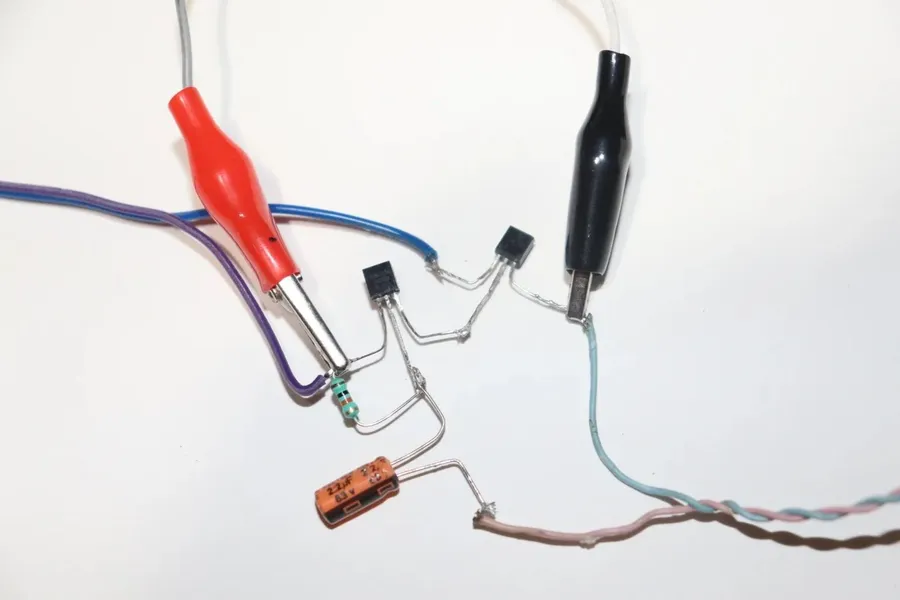
The BC547 transistor, a versatile NPN BJT, finds extensive use in diverse electronic applications primarily due to its effectiveness in amplification and switching. Its low cost, widespread availability, and reliable performance make it a staple in both hobbyist and professional electronics design. This section will illustrate its practical usage in amplifier and switching circuits, demonstrating its functionality and adaptability.
One of the main applications of the BC547 is in small-signal amplification, where it can boost weak electrical signals, making them suitable for further processing. A simple single-stage amplifier circuit is often used as an audio pre-amplifier or a gain stage in other analog circuits, leveraging the BC547’s current gain (hFE) properties. For example, an electret microphone signal may need amplification to become useful for audio processing by a microcontroller or an amplifier IC. The gain will depend on the biasing resistors.
The switching capability of the BC547 is also a core function, which allows it to control larger electrical loads using a small input signal. In a typical switching application, a small current at the base pin can drive the transistor into saturation, allowing a much larger current to flow between the collector and emitter. A common scenario includes using the BC547 to switch LEDs, relays, or small DC motors. For example, a digital logic signal from a microcontroller can control the base pin which then will turn a relay on or off via the emitter-collector path.
| Application | Description | Circuit Example |
|---|---|---|
| Small-Signal Amplifier | Amplifies weak signals using current gain (hFE). | The input signal is applied to the base of the transistor, and the amplified signal is output from the collector. The biasing resistors establish the operating point of the transistor. The amplification can be tuned by changing the biasing values. |
| Switching Circuit | Controls larger loads by turning them on or off with a control signal. | The control signal is applied to the base, which switches the transistor between the cut-off and saturation regions, thereby controlling the current in the emitter-collector path. This can be used to drive an LED, relay, or a motor. |
The implementation of a BC547 as an amplifier requires careful selection of biasing resistors to set the operating point (Q-point). The Q-point determines the gain and linearity of the amplifier. In simple terms, the values of resistors should allow the transistor to operate in the linear or active region where amplification occurs without distortion. In contrast, for switching applications, it is desirable to drive the transistor into saturation where the emitter-collector path is almost a short circuit, and the voltage drop across it is minimal. In such a scenario, the base current needs to be high enough to ensure the transistor is fully 'ON'.
The BC547 transistor is available in several variants, primarily distinguished by their DC current gain (hFE) ranges. These variants, BC547A, BC547B, and BC547C, offer designers a choice based on their specific amplification needs. Understanding these differences is crucial for optimal circuit performance.
| Variant | hFE Range | Typical Application |
|---|---|---|
| BC547A | 110 - 220 | General-purpose amplification and switching where a lower gain is acceptable. |
| BC547B | 200 - 450 | General-purpose amplification where a moderate gain is required. |
| BC547C | 450 - 800 | Applications needing a higher current gain, such as sensitive sensor interface circuits. |
The hFE, also known as the forward current gain, is the ratio of collector current (Ic) to base current (Ib). A higher hFE means that a smaller base current can control a larger collector current, resulting in more efficient amplification or switching. While choosing a BC547 variant, it is important to understand the implication of hFE to ensure stable operation over temperature and variability due to component tolerances. For instance, when using in an amplifier circuit, a higher gain variant may be more sensitive to noise whereas, a lower gain variant may require higher base current. In switching applications, the variants may affect the switching speed.
While the BC547 transistor is a versatile and widely used NPN BJT, situations may arise where a substitute is necessary due to availability or specific circuit requirements. Several transistors can serve as viable alternatives, each with its own set of characteristics that may offer advantages or present limitations compared to the BC547. Understanding these differences is crucial for successful circuit design and implementation.
| Transistor | Type | hFE (Typical) | Max Collector Current (Ic) | Max Collector-Emitter Voltage (Vce) | Typical Application | Notes |
|---|---|---|---|---|---|---|
| BC547 | NPN | 110-800 | 100mA | 45V | General Purpose | Widely available and cost-effective. |
| BC548 | NPN | 110-800 | 100mA | 30V | General Purpose | Very similar to BC547, often interchangeable. |
| BC549 | NPN | 200-900 | 100mA | 30V | Low Noise Amplifier | Higher hFE than BC547, suited for low-noise applications |
| BC550 | NPN | 200-900 | 100mA | 45V | Low Noise Amplifier | Higher hFE and slightly higher voltage ratings |
| 2N2222 | NPN | 100-300 | 800mA | 40V | High Current Switching | Higher current handling capability, different pinout. |
The table above provides a concise comparison of the BC547 and its potential substitutes. Note that hFE values can vary significantly even within the same transistor type due to manufacturing tolerances. When substituting, it's critical to consider not just the typical values but also the minimum and maximum ranges specified in the respective datasheets. Specifically, the 2N2222, while a capable NPN transistor, has a different pinout arrangement compared to the BC547 series (E-B-C vs. C-B-E) and significantly higher current capacity, making it more suitable for switching higher current loads or as a driver for other high current devices. Using the 2N2222 as a direct drop in replacement for the BC547 without understanding these fundamental differences will typically result in circuit malfunctions.
While the BC548 is often a suitable, almost drop-in replacement for the BC547 due to their extremely similar characteristics, the BC549 and BC550 transistors are higher gain variations and therefore may require alterations to the bias network when used as replacements for the BC547. It is crucial to consult the datasheets for all components being considered as replacements and verify performance. A direct substitution might not always yield the same results, so careful selection and testing are essential.
This section addresses common questions about the BC547 transistor, providing clear and concise answers to help users understand its function and application in electronic circuits.
Effective troubleshooting of BC547 circuits requires a systematic approach, addressing common issues such as improper biasing, component failures, and incorrect wiring. Understanding the typical failure modes of the transistor and how to test it are essential for reliable circuit operation.
While the BC547 is a robust and versatile transistor, optimizing its performance in demanding applications requires attention to several advanced considerations. This section delves into best practices for heat management, noise reduction, and overall circuit performance enhancement.
Effective heat management is crucial, particularly when the BC547 operates near its maximum ratings or in high-ambient temperatures. Proper circuit design and component selection are essential to prevent thermal runaway and ensure long-term reliability. Similarly, understanding and mitigating noise is critical in sensitive applications, and it often requires using decoupling techniques and appropriate grounding strategies.
These advanced techniques help ensure that the BC547 not only functions correctly but also performs reliably and efficiently in a wide range of applications. Paying attention to these details will result in better circuit designs.
The BC547 transistor, a reliable and widely used NPN device, is a cornerstone of many electronic circuits. This guide has provided a deep dive into its pinout, specifications, and practical applications. From understanding its role in amplifiers and switching circuits to exploring equivalents and troubleshooting, the information presented equips readers to use the BC547 effectively. The BC547, while seemingly simple, plays a critical part in a vast array of electronic systems and continuing to explore and experiment with it could open up more possibilities in circuit designs. By understanding its nuances and characteristics, one can make informed decisions in circuit design, and it encourages one to explore more of the electronics field.

