Decoding the Fuzz Factory Layout: A Comprehensive Guide
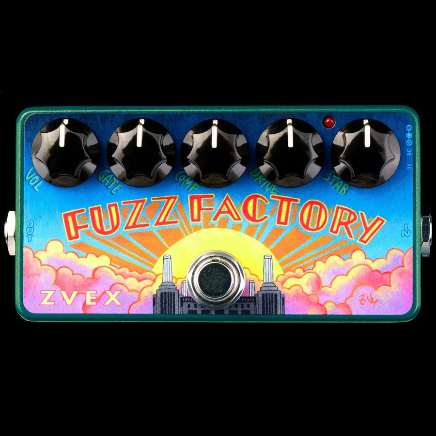
The ZVex Fuzz Factory, a legendary fuzz pedal, is renowned for its unpredictable and wild tones. Its unique circuit design often sparks curiosity among DIY pedal enthusiasts. Understanding the Fuzz Factory layout is crucial for those wanting to build, modify, or troubleshoot this iconic pedal. We'll delve into various layouts, explain their nuances, and provide a comprehensive understanding of this chaotic circuit, and finally, empower you to embark on your own fuzz factory journey.
Understanding the Core Components of the Fuzz Factory
The Fuzz Factory's distinctive and chaotic sound is born from the interaction of a few key components: germanium transistors, potentiometers (pots), and capacitors. These parts, when combined within a specific circuit, create the highly responsive and unstable fuzz that defines the pedal. Each component, with its unique role, contributes to the wide range of tones and the pedal's sensitivity to input.
Germanium transistors, critical to the Fuzz Factory's character, introduce specific non-linear behaviors that greatly contribute to the pedal's sound. Potentiometers provide variable resistance, allowing the user to finely tune parameters such as oscillation, gate, and compression, offering a rich array of tonal possibilities. Capacitors are utilized for filtering and shaping the frequency response, further influencing the overall sound of the pedal by controlling the tonal qualities and the gain structure.
| Component | Role in Fuzz Factory | Impact on Sound |
|---|---|---|
| Germanium Transistors | Amplification and signal distortion | Introduce unique non-linear distortion and contribute to the pedal's characteristic fuzz. |
| Potentiometers (Pots) | Variable resistance for parameter control | Allow users to control gain, oscillation, gate, and compression, greatly altering the tone and behavior. |
| Capacitors | Filtering and frequency shaping | Shape the overall frequency response, filtering specific frequencies and altering the tonal character of the fuzz. They also impact the gain structure. |
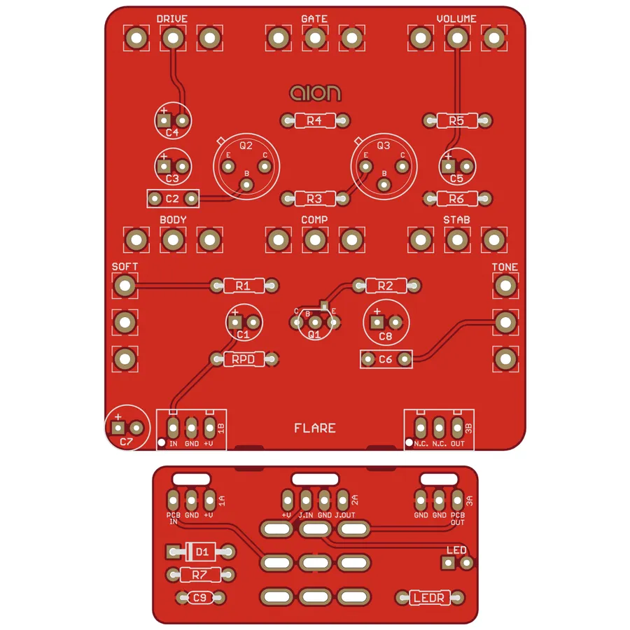
The Original ZVex Fuzz Factory Layout: An Overview
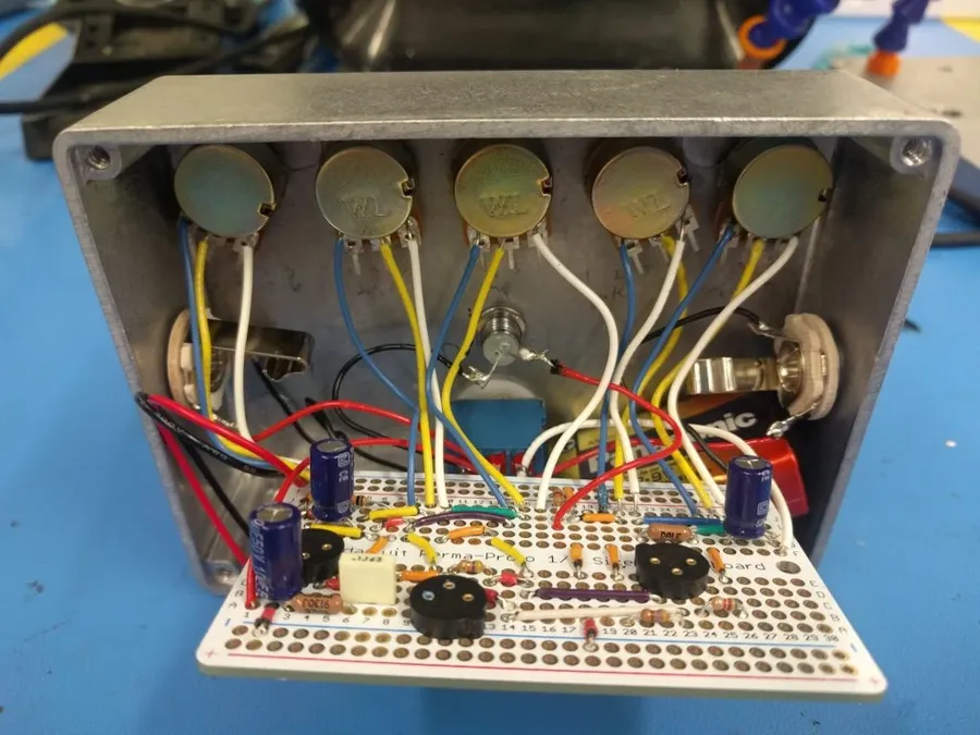
The original ZVex Fuzz Factory layout is characterized by its distinctive component arrangement, a design choice driven by both sonic and practical considerations. This layout, while seemingly unconventional, contributes significantly to the unique and often unpredictable tonal character of the pedal. The positioning of components is not arbitrary but rather a careful configuration that encourages specific interactions within the circuit.
The core of the original Fuzz Factory centers around two germanium transistors, often NPN type. These transistors are highly sensitive and their gain characteristics are greatly influenced by the surrounding circuitry. The layout, often not optimized for the shortest possible signal path, instead prioritizes component interaction to achieve the intended range of fuzz and oscillation. Unlike modern PCB layouts, the original often featured a more organic, hand-wired approach.
Key features of the original layout include the use of point-to-point wiring or stripboard construction with components spaced to allow for a degree of 'component bleed' which contributes to the unstable and dynamic character of the pedal. Potentiometers, in particular, are placed in a way that makes their interaction highly influential, leading to the erratic yet musical behavior the Fuzz Factory is famous for. The capacitance and resistance values across the circuit create dynamic and complex interactions, and the component spacing contributes to that effect.
Understanding the original ZVex Fuzz Factory layout is essential for those seeking to replicate its exact sonic qualities or appreciate the design philosophy behind it. It is not just a question of placing components but about how those components are placed to maximize specific nonlinearities and interactions. The unique configuration, with its slightly chaotic appearance, is crucial to the Fuzz Factory’s distinctive performance. This inherent instability is a core component of the pedal’s character, which is why exact replication is sought after by many DIY enthusiasts.
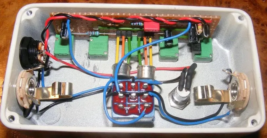
Compact Fuzz Factory Layouts: Saving Space
The inherent complexity of the Fuzz Factory circuit, with its five potentiometers and multiple transistors, often leads to large enclosures. However, compact layouts address this by optimizing the component arrangement to fit within smaller enclosures, most commonly the 1590B enclosure, without compromising the core functionality and sonic characteristics of the pedal. These designs are crucial for pedal builders who prioritize space efficiency on their pedalboards.
Compact layouts achieve their reduced footprint through several strategies. Component selection plays a crucial role, with the use of smaller capacitors and resistors being common. The arrangement of potentiometers and transistors is also optimized, placing them closer together and, where possible, using vertical mounting or stacked components. Furthermore, the layout often minimizes the use of large amounts of wiring by strategically placing components to allow for direct connections.
Optimizing for the 1590B enclosure has become a focus due to its compact size and popularity among DIY pedal builders. These enclosures demand precise layout planning, often involving custom PCBs or carefully laid out Vero board designs to maximize the usable space. Specific attention is given to the spacing around mounting hardware and the height of components to ensure they don't interfere with the enclosure.
The main advantages of compact layouts are the reduced size for easier pedalboard integration, ease of handling when building and a lower material usage which can reduce overall cost. On the other hand, the challenges associated with compact builds include the higher precision required for assembly, increased component density which can make troubleshooting more difficult, and potential for signal noise if layout is not carefully thought out.
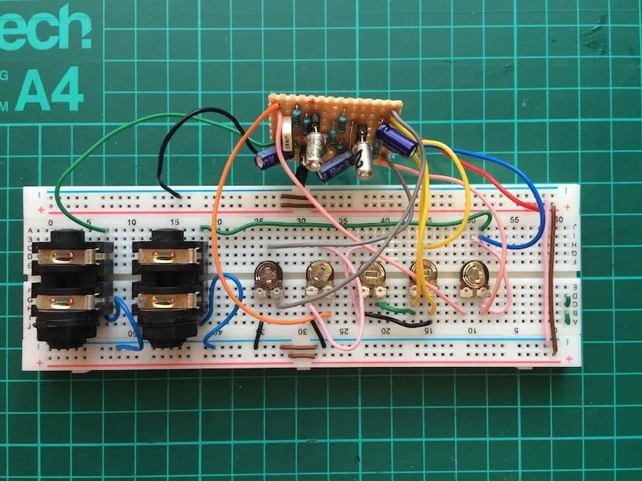
Vero Board vs. PCB Layouts: A Comparative Analysis for Fuzz Factory Builds
When constructing a Fuzz Factory, the choice between Vero board (stripboard) and Printed Circuit Board (PCB) layouts significantly impacts the building process, signal integrity, and overall project suitability. Each method presents unique advantages and disadvantages that must be carefully considered based on the builder's experience and project requirements. This section will provide a structured comparison to aid in making an informed decision.
| Feature | Vero Board (Stripboard) | PCB |
|---|---|---|
| Ease of Building | Generally easier for beginners due to its straightforward layout and minimal specialized equipment; requires more careful attention to avoiding shorts through proper cuts. | Can be more complex to assemble initially if not using a through-hole kit, but once all parts are in place, it has an easier, more consistent build process; typically designed to minimize assembly errors. PCBs designed for SMT components require more specialized equipment |
| Signal Integrity | Prone to parasitic capacitance and less controlled impedance, which can impact the circuit's performance, especially in high-gain scenarios, if not constructed carefully. In general, it's more susceptible to environmental noise. | Offers superior signal integrity due to controlled trace impedance and layout optimization, which leads to less noise, parasitic capacitance, and better performance in high-gain scenarios, if the circuit is well designed. PCBs usually have ground planes that make them less susceptible to environmental noise. |
| Component Density | Relatively lower component density due to the fixed grid spacing, which can make compact layouts challenging, and more prone to short-circuits if not carefully planned out. | Higher component density is achievable, making it suitable for compact enclosures; can accommodate surface mount components for even greater density. |
| Customization | Highly customizable, allowing for easy modifications and experimentation with component values; easy to build single prototypes or small batches. | Less customizable after fabrication, but provides more accurate and consistent results for larger batches; often requires redesign if significant modifications are needed. |
| Cost | Lower upfront cost for materials and tools, especially for one-off builds; ideal for prototyping and testing. Typically uses commonly available components. | Higher initial cost due to fabrication, but can be cost-effective for larger runs; has a wider component selection, but it can also be pricier. |
| Suitability | Best for one-off projects, learning, or small modifications; good for experimenting with different sounds; easier to repair. | Best for larger production runs, or for those who require reliability and consistent performance; offers greater durability. |
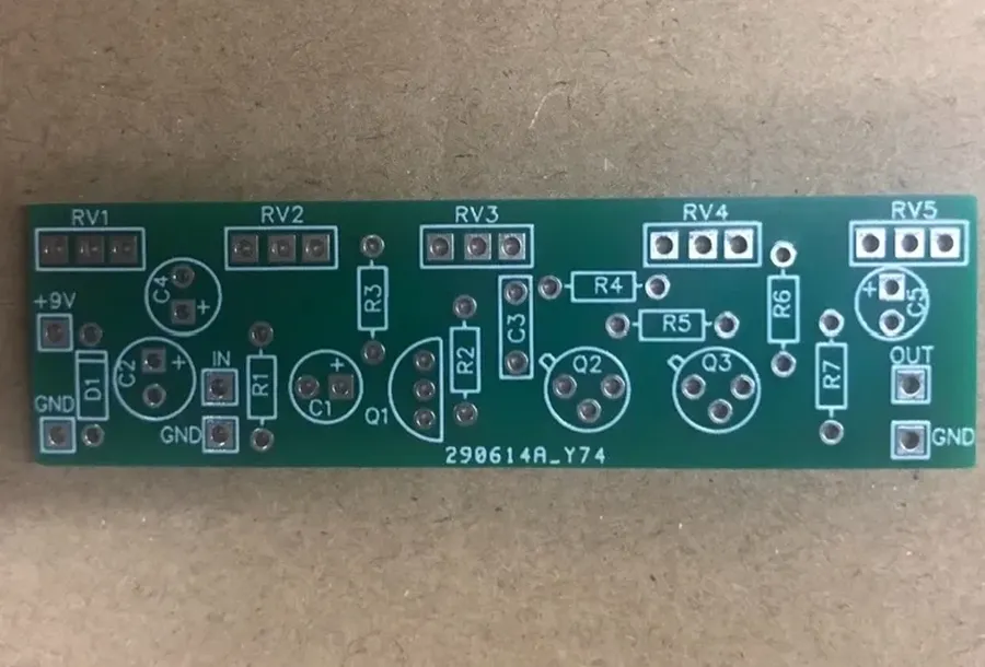
Schematics and Circuit Analysis of the Fuzz Factory
Analyzing the Fuzz Factory schematic provides crucial insights into its signal flow and component interaction, essential for builders seeking a comprehensive understanding of this unique pedal. A deep dive into the schematic illuminates the nonlinearities inherent in the design, which are responsible for the wide range of chaotic and unpredictable sounds it can produce. This section is specifically tailored to help builders effectively interpret the schematic.
The Fuzz Factory circuit is based around a three-transistor topology, with each transistor stage contributing to the complex distortion and oscillation characteristics. Understanding the role of each stage is essential for effective building and troubleshooting.
- Transistor Stages
The circuit employs three transistors, typically germanium type, each contributing to gain and clipping. The biasing of these transistors determines the overall behavior of the circuit. - Capacitor Interactions
Capacitors in the circuit interact with the transistor stages to shape the frequency response and control oscillation characteristics. Their values determine the bandwidth and feedback characteristics. - Potentiometers and their Influence
The Fuzz Factory uses potentiometers (pots) to alter the bias of transistors, and adjust the input and output impedance of each stage. These parameters drastically change the overall tone and gain and are the key to the circuit's dynamic response.
Key aspects for builders when interpreting the schematic include tracing the signal path from the input jack through the transistors and finally to the output jack. This process helps in comprehending how each control interacts with the signal and shapes the final sound. Identifying the critical feedback paths will allow builders to understand the complex interactions that leads to the unique sound of the Fuzz Factory.
| Component | Function | Impact on Tone |
|---|---|---|
| Transistors (Q1, Q2, Q3) | Signal amplification and clipping | Determines gain, distortion and oscillation characteristics |
| Capacitors (C1, C2, etc.) | Frequency shaping and coupling | Controls bass response, oscillation and overall tone |
| Potentiometers | Variable resistance for biasing and signal control | Adjusts gain, feedback, and allows for wide range of sonic possibilities |
| Resistors (R1, R2, etc.) | Bias setting and current limiting | Determines operating point of transistors and impedance of the circuit |
Modifications and Variations: Expanding the Fuzz Factory's Sonic Palette
The Fuzz Factory, while iconic in its raw form, is often modified to further tailor its sound. These modifications range from subtle tweaks to radical alterations, each influencing the pedal's sonic character. These adjustments often center around adding tone controls, altering gain structures or component substitution. This section details some popular modifications and their respective impacts on the Fuzz Factory's sound.
- Tone Control Addition
Implementing a tone control is one of the most popular Fuzz Factory modifications. Typically, this involves adding a potentiometer and capacitor, forming a low-pass filter to adjust the high-frequency content of the output signal. This offers more control over the often harsh treble frequencies inherent in the stock Fuzz Factory. - Fat Switch Modification
A 'fat switch' is a modification that adds a capacitor to the input stage, increasing bass frequencies. This typically adds a larger capacitor between the input signal and the first transistor's base, allowing more low-end frequencies to pass into the circuit, resulting in a thicker sound. - Transistor Substitution
The Fuzz Factory's tone is heavily influenced by its germanium transistors. Substituting these for silicon transistors will dramatically alter the sound, usually providing more gain, a tighter low end, and a brighter tone. Different germanium transistors will also offer sonic variations due to variations in their gain (hFE) and leakage. Experimenting with transistors can be a great way to find a more usable range of tones. - Input Impedance Adjustments
Tweaking the input impedance can significantly alter how the Fuzz Factory interacts with different guitars and other pedals. Often, a resistor of different value is placed at the input signal to alter the impedence and the way the signal reacts to the circuit. Some modifications place a trimpot here for adjustable impedence. - Bias Adjustments
Adjusting the bias points of the transistors can lead to a different feel, responsiveness and sonic characteristics in the Fuzz Factory. This often comes in the form of a potentiometer wired in such a way as to alter the voltage applied to the transistors base or collector.
Troubleshooting Common Issues with Fuzz Factory Builds
Building a Fuzz Factory can be a rewarding experience, but it's not without its challenges. This section addresses common problems encountered by DIY builders, providing a systematic approach to diagnosing and resolving issues to ensure your Fuzz Factory operates as intended.
- No Output
If no sound is produced, first verify the power supply and its polarity, ensuring it meets the requirements of the circuit. Next, check all solder joints for proper connections; cold solder joints and shorts are frequent causes of no output. Lastly, check the wiring of the input/output jacks and footswitch. - Low Output or Weak Signal
A weak signal can stem from various issues. Begin by examining the transistor biasing by measuring voltages across each component as recommended in the build documentation. Inconsistent biasing can result from incorrect component values, particularly with transistors that have variable gain. The signal path may also be the cause, so verify the continuity from input to output with a multimeter. - Excessive Noise or Hiss
High noise levels can originate from several sources. Review your soldering, making sure there are no solder bridges or short circuits that might introduce noise into the signal. Ensure that the components are isolated from the enclosure, which can sometimes introduce noise, or cause ground loops. In some cases, the transistors themselves may be inherently noisy, so substituting different components can sometimes help. - Unstable or Erratic Behavior
Instability can manifest as unpredictable oscillations or a circuit that seems to have a mind of its own. Carefully review the value of components, especially the capacitors. Incorrect values can drastically alter the way the circuit operates. The layout can also contribute to such issues, so make sure the board or stripboard matches the schematic. - Potentiometers Not Responding
If the potentiometers aren't producing the desired changes, first make sure they are properly connected to the board with no shorts. Second, make sure they are the correct value and taper. Lastly, check for any damaged potentiometers using a multimeter for resistance variation when turned. - Incorrect Transistor Biasing
The germanium transistors used in the Fuzz Factory are very sensitive to biasing. Measure the voltage on each pin of the transistor using a multimeter. Compare these measurements with the ones provided in the documentation to ensure correct values. If the bias is off, it may require substituting transistors with different gains or adjusting surrounding resistors to compensate for transistor variations.
Frequently Asked Questions About Fuzz Factory Layouts
This section addresses common queries regarding the Fuzz Factory layout, covering aspects from component selection to construction methods. These frequently asked questions (FAQs) are designed to clarify typical user pain points and provide concise solutions for successful builds and modifications.
- What are the critical components to consider when choosing transistors for a Fuzz Factory build?
Germanium transistors are pivotal for the Fuzz Factory's signature sound. The hFE (current gain) and leakage of these transistors drastically affect the fuzz's behavior. It's not just the type, but also carefully selecting and pairing transistors with appropriate gain is crucial. Aim for transistors with hFE values within the 70-130 range, and moderate leakage. - Is it possible to use silicon transistors in a Fuzz Factory circuit?
Yes, silicon transistors can be used, but the sonic characteristics will differ significantly. Silicon transistors typically have higher gain and lower noise, resulting in a brighter and more aggressive fuzz. This modification will also require changes to the bias and may require component swaps to achieve optimal results. - What's the best way to troubleshoot a Fuzz Factory circuit that's not working as expected?
Start by checking your wiring and component placement for errors against the layout. Measure voltages at different points in the circuit to ensure they match the expected values based on the schematic, with a particular focus on the transistor collector voltages. Also, make sure that your potentiometers are functioning properly, check for solder shorts, and ensure correct polarity of polarized components. A good build should typically produce some fuzz tone regardless of the knob settings. If there's no tone, you have a problem! - Which type of layout is better for a beginner: Vero board or PCB?
For beginners, Vero board (stripboard) is often more accessible due to its flexibility and lower initial cost. It allows for easier component placement and circuit modifications. However, PCB (printed circuit board) layouts tend to be more reliable once properly designed, because they provide a more standardized and consistent circuit. PCBs are often more time-consuming and costly to set up for, unless you use online PCB fabricators with low-cost prototyping. - What are some common modifications to a Fuzz Factory that can alter its tone significantly?
Several modifications can dramatically alter the tone. Adding a tone control (e.g., a Big Muff tone stack) helps shape the fuzz's EQ. Incorporating a 'fat' switch increases the bass response. Switching out the germanium transistors for silicon variants provides a brighter and more aggressive tone. Additionally, experimenting with different capacitor values can also shape the overall tone of the fuzz. - How does the placement of components impact the Fuzz Factory's sound?
The Fuzz Factory's circuit is sensitive to parasitic capacitance and component lead lengths. It's best to keep components relatively close together, avoid unnecessarily long leads, and maintain consistent component placement as much as possible. While not a huge impact, different layouts can potentially change tone due to different parasitic properties. - What is the purpose of the 'Gate' knob on the Fuzz Factory?
The Gate knob on a Fuzz Factory is designed to control the threshold of signal allowed to pass through the circuit and it controls the bias of the second gain stage. At higher gate settings, the circuit will choke the signal, effectively cutting off the fuzz and producing spluttering, gated sounds. It interacts with other controls to provide different flavors of the fuzz and is a unique attribute to the fuzz factory.
Understanding the Fuzz Factory layout empowers musicians and DIYers to explore the wild world of fuzz. By delving into its various layouts, schematics, and modifications, you can not only build your own but also tailor its unique sonic chaos to your specific needs. Whether you're a seasoned builder or a curious beginner, the Fuzz Factory offers an exciting opportunity to experiment and create a truly personalized tone. Armed with this knowledge, you're now ready to embark on your own fuzz journey, shaping your sound in a unique and captivating way.