Simplify Arduino Projects: Your Guide to the Best Arduino Layout Makers
In today's tech-driven world, electronics have become an integral part of our lives, with Arduino boards leading the charge in DIY electronics projects. However, designing the right layout and schematic for your Arduino project can be a daunting task. This article explores various user-friendly Arduino layout makers designed to streamline your projects, whether you're a seasoned engineer or just starting out. From online tools to software applications, we'll help you find the perfect fit to bring your innovative ideas to life with ease using an Arduino layout maker.
Understanding the Importance of a Good Arduino Layout
A well-structured Arduino layout is fundamental to the success and reliability of any electronics project. It's not merely about aesthetics; a thoughtfully designed layout prevents common issues such as short circuits, facilitates efficient troubleshooting, and ensures a clean, organized build. Crucially, a good layout allows for clear visualization of the final design before committing to physical construction, saving time and resources.
- Preventing Short Circuits
Careful component placement and wiring reduces the risk of unintended electrical connections, which can damage components and cause project failure. - Simplifying Troubleshooting
An organized layout makes it easier to trace connections and identify the source of problems when debugging. - Ensuring a Clean Build
A neat and logical layout improves the overall reliability and maintainability of the project. - Visualizing the Final Design
Planning out the layout allows you to understand how the project will look and function, which aids in planning.
Online Arduino Layout Makers: Convenience at Your Fingertips
Online Arduino layout makers provide unparalleled convenience for designing and visualizing your projects. Accessible from any device with internet connectivity, these tools eliminate the need for specialized software installations and offer collaborative features ideal for team projects. The intuitive drag-and-drop interfaces and pre-built component libraries streamline the design process, making them perfect for rapid prototyping and experimentation.
- Accessibility
Access your projects from any internet-enabled device, ensuring you can work anywhere. - Collaboration
Enable real-time collaboration on shared projects, facilitating teamwork and efficient design processes. - Ease of Use
The drag-and-drop functionality and intuitive interfaces make these tools simple to learn. - Cost-Effectiveness
Many online platforms offer free tiers or free trial periods with comprehensive features, reducing costs. - Component Libraries
Provides libraries with pre-built component models that can be used in layout designs, making circuit assembly more efficient.
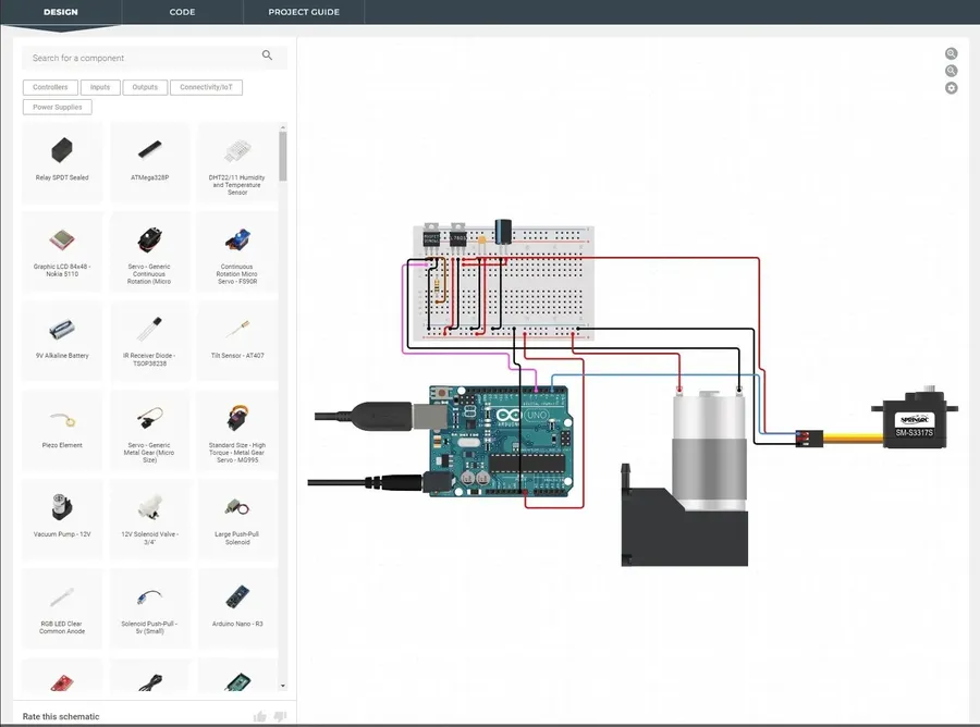
Popular platforms like Tinkercad and circuito.io exemplify these benefits by providing an extensive array of components that can be added to your projects in a visual manner. These tools also provide virtual breadboard environments for testing components.
Software for Advanced Arduino Schematic Design

For complex Arduino projects that demand precise control and detailed design, dedicated schematic capture software is essential. These tools extend beyond simple layout design, providing a comprehensive environment for creating intricate circuit diagrams. They are particularly useful for projects requiring custom components or a high degree of design specificity, enabling a more structured and efficient approach to circuit development. ExpressSCH, with its custom part capabilities and user-friendly interface, is a prime example of such software.
Unlike basic layout tools, advanced schematic software allows for a more detailed representation of the circuit, showing not just the physical arrangement of components but also their electrical connections and logical relationships. This deeper level of design control is crucial for identifying potential issues, optimizing performance, and documenting the circuit for future reference or collaboration.
Key Features to Look for in an Arduino Layout Maker
Selecting the right Arduino layout maker hinges on several key features that enhance the design process. An effective tool should streamline your workflow, reduce errors, and ultimately help bring your project to life efficiently. Essential features include an intuitive user interface, a comprehensive library of components, real-time simulation, and automatic BOM generation.
- Intuitive User Interface
A user-friendly interface is crucial for both beginners and experienced users. The layout maker should be easy to navigate, with clearly labeled tools and functions. Drag-and-drop functionality, simple menu navigation, and clear visual feedback are desirable traits. The learning curve should be minimal, allowing users to focus on design rather than struggling with the software. - Comprehensive Component Library
A rich library of components is essential for any good layout tool. This should include a wide variety of commonly used Arduino components, sensors, actuators, and integrated circuits. The ability to search for specific parts by name or part number and a clear way to display the attributes of each component is a must. Furthermore, a robust library also allows for community submitted components or the user to be able to design their own component library to use in their design. - Real-Time Simulation Capabilities
Real-time simulation allows users to test the functionality of their designs virtually, identifying potential issues or errors before physical implementation. This feature allows users to understand circuit behavior, verify connections, and save time and resources by catching issues early. A good simulation tool should accurately reflect the real-world behavior of the components and be able to show problems that may arise in operation. - Automatic Bill of Materials (BOM) Generation
The ability to generate a BOM automatically can significantly reduce the time spent preparing for a build. The BOM should list all components used in the project along with the quantities and reference designators. The ability to export the BOM in common formats like CSV or Excel can further streamline the process for sourcing components. This greatly simplifies the procurement process and eliminates manual tracking of each component used.
Arduino Circuit Simulators: Testing Your Design Virtually
Virtual circuit simulation is an essential phase in Arduino project development, allowing engineers and hobbyists to validate their designs and identify errors before committing to physical assembly. By simulating the circuit's behavior under various conditions, users can refine their designs, optimize component selection, and avoid the time-consuming and costly process of trial-and-error on physical hardware.
Circuit simulators also offer educational benefits. By observing the flow of current and voltage in real-time, users can develop a deeper understanding of electrical engineering principles, enhancing their ability to design effective circuits.
- Key Benefits of Arduino Circuit Simulators:
Utilizing a circuit simulator provides significant advantages, such as cost reduction by preventing component damage through virtual testing, time efficiency by identifying design flaws early, and improved understanding of circuit behavior in a visual, interactive environment. - Real-Time Analysis:
Simulators often display real-time data including voltages and currents, making it easier to grasp the intricacies of circuit operations. - Component Libraries:
Most simulators contain extensive component libraries, that allow for design and simulation of almost any kind of circuit. - Interactive Adjustments:
Users can modify component values and simulate the effect of those changes in real-time. - Error Identification
Simulators can automatically identify design issues like short circuits, incorrect component orientation, and power supply issues.
Frequently Asked Questions About Arduino Layout Makers
This section addresses common questions users have regarding Arduino layout makers, providing clear and concise answers to help you choose the right tools and approach for your projects.
- How can I find a free Arduino layout maker online?
Several online platforms offer free Arduino layout maker tools. These include Tinkercad, which is widely used for educational purposes and basic circuit design, and circuito.io, which is known for its ability to create board layouts based on connected components. Look for 'free' options within the tool's account or pricing plans. - What is the difference between schematic design software and layout tools?
Schematic design software focuses on representing the circuit's logic and connections using symbols. It's a high-level abstraction of the circuit, while layout tools are concerned with the physical arrangement of components on a board, determining how they are actually connected. Schematic software precedes layout tools in the design workflow. - How do I choose the best Arduino layout tool for my specific project?
Consider the complexity of your project. For simple projects and learning, online tools like Tinkercad are sufficient. For more complex projects and professional needs, dedicated software like Fritzing or professional level EDA software, which may require a purchase, are more suitable. Also consider the need for simulation and collaboration tools when making a choice. - Which Arduino layout tools are best for beginners?
Beginners should start with user-friendly online platforms like Tinkercad. Its drag-and-drop interface and simulation capabilities make it easy to learn the basics of circuit design. It is easily accessible via the browser and the learning curve is quite gentle. - Is it necessary to learn specific software to create Arduino layouts?
While not strictly necessary, learning to use specialized software will significantly improve your workflow, capabilities, and allow for more intricate layouts to be achieved. Simple layouts can be accomplished without learning too much, but for professional projects and re-useable designs, a focused software based approach will yield far better results. - Can I simulate my Arduino circuit designs before building them?
Yes, many layout tools offer simulation capabilities. Tinkercad, for example, allows you to simulate your circuit's behavior before building it physically. This can save you time and avoid potential errors when prototyping. Using a simulator is strongly advised before physically building any circuit, not only for error prevention but for understanding circuit behavior. - How can I create custom components in an Arduino layout maker?
Some software, such as ExpressSCH, provides the functionality to design and add custom parts, allowing a high degree of flexibility for advanced users. This requires the user to understand the required dimensions and pin-outs of the custom component. Custom components can also be created as required in some professional EDA tools.
Comparative Analysis of Arduino Layout Makers
Selecting the right Arduino layout maker is crucial for efficient project development. This section provides a comparative analysis of popular options, evaluating them based on user-friendliness, features, cost, and suitability for different skill levels and project requirements. This comparison helps users identify the best tool for their specific needs, highlighting the advantages and disadvantages of each option.
| Tool | User-Friendliness | Key Features | Cost | Suitability |
|---|---|---|---|---|
| Tinkercad | Beginner-friendly, intuitive drag-and-drop interface | 3D design, virtual simulation, component library | Free | Beginners, simple to medium complexity projects |
| Fritzing | Moderate learning curve, focuses on visual schematic representation | Customizable parts, breadboard and schematic views | Free/Paid (Donation based) | Intermediate users, electronics enthusiasts, those needing detailed visualizations |
| EasyEDA | Moderate to Advanced, online, feature rich | PCB design, schematic capture, simulation and community support | Free with paid plans for advanced features | Professional use, complex projects, circuit board design |
| Autodesk Eagle | Advanced, industry standard | Comprehensive PCB design tools, schematic capture | Paid subscription model | Professional engineers, complex PCB design |
| Upverter | Moderate, Web-based platform | Collaborative design, schematic capture, PCB layout | Free for small projects, Paid for larger projects and advanced features | Collaborative teams, educators, simple to complex designs |
| ExpressSCH | Moderate, Easy to use interface with a parts creation feature | Schematic Design, parts creation | Free | Beginners to advanced users, schematic creation and complex circuit design. |
Step-by-Step Guide: Using an Arduino Layout Maker for Beginners
This guide provides a foundational understanding of how to use an Arduino layout maker, specifically focusing on the initial steps to get a beginner up and running. We'll walk through the process using a common online tool, emphasizing simplicity and ease of use.
- Selecting a Suitable Online Layout Maker
For this guide, we will use Tinkercad, a free, user-friendly online platform known for its intuitive interface, and beginner accessibility. Access Tinkercad through your web browser; no software installation is needed. Tinkercad offers a comprehensive component library and a simple drag and drop interface for constructing circuits. - Creating a New Project
Once you've logged into Tinkercad, navigate to the 'Circuits' section and select 'Create new Circuit'. This initiates a new project space where you can begin building your Arduino circuit. - Adding Essential Components
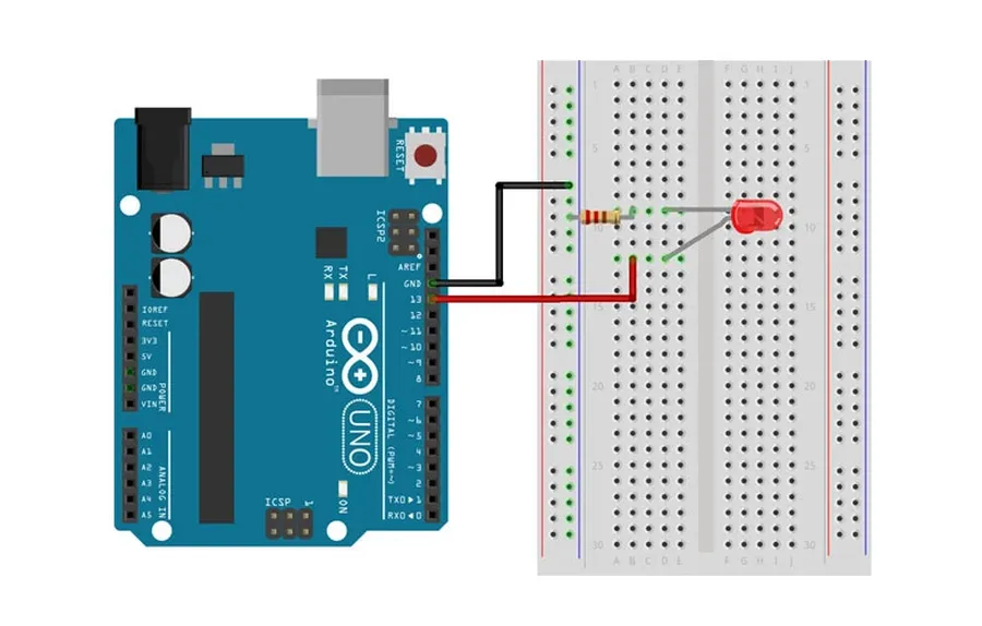
From the component list to the right, drag and drop the necessary components onto your virtual breadboard. Essential components for a basic project might include: an Arduino board (UNO), a breadboard, an LED, a resistor, and connecting wires. These components can be found within the 'Components' menu. Start by placing the Arduino board, then add the breadboard next to it. - Placing and Connecting the LED
Add the LED to your breadboard, making sure to orient it correctly. LEDs have a positive (anode) and a negative (cathode) leg. Connect the anode leg of the LED to a current-limiting resistor. It's important to choose the right resistor to protect the LED from overcurrent; a 220 ohm resistor is common for most standard LEDs. Finally, connect the other end of the resistor to a digital output pin on the Arduino board, like pin 13. Connect the cathode leg of the LED to the ground pin on the Arduino board. You can wire the components by clicking on the output pin of the component you want to connect from and dragging the cursor to the input pin of the next component. - Wiring the Circuit
Using the virtual wires from the component menu, connect the components as described above. Make sure that the wire colors are easy to follow and to not overlap components. Wiring accurately is key to circuit functionality, ensure that no connections are missed. Using different color wires will allow you to trace the different connections and make sure they are correct. - Testing your Circuit
Once your virtual circuit is complete, click the 'Start Simulation' button. This will allow you to see how your circuit will react to the code that runs on the Arduino. If your circuit is set up properly, you will be able to see the LED turn on and off. If it is not, it will be an easy way to troubleshoot before building a physical circuit. You can easily correct and modify the wiring if it is needed.
Tips for Efficient Arduino Circuit Design
Efficient Arduino circuit design is crucial for creating reliable, maintainable, and easily testable projects. Proper planning and execution in the virtual design phase can save significant time and resources during the physical build and testing stages. Adhering to best practices ensures that your circuits are not only functional but also robust and straightforward to troubleshoot.
- Plan Before You Place:
Before placing any component, sketch out your circuit on paper or a digital whiteboard. This helps visualize the flow of electricity and identify potential bottlenecks or issues. Consider the physical arrangement of components for ease of access, testing and future modifications. This initial step can mitigate errors downstream. - Prioritize Component Grouping:
Group related components together to keep the circuit layout organized. This simplifies tracing connections and reduces clutter, and it is easier to make modifications if the components are arranged logically based on their function in the circuit. Components that interact with each other should be placed in close proximity. - Utilize Logical Wiring Strategies:
Strive for the shortest wire lengths possible to minimize resistance and potential signal degradation, especially for circuits using analog signals. Avoid crossing wires where possible, or use jumpers to minimize any confusion in the routing. Use color coding on your virtual schematics to clarify and differentiate between different functional elements in the circuit. - Strategic Component Placement:
Consider component orientation and how they will interact physically. Ensure that any components that will need manual access, like potentiometers or buttons are easily accessible. Be mindful of the physical sizes of components, and avoid overlapping components if they will need to be placed in a physical layout. - Consistent Grounding Techniques:
Implement a consistent ground plane to avoid noise and ensure stable operations, a well-established ground plane is the basis for any good circuit. Minimize ground loops by having a single point ground reference and use bus lines where necessary to distribute ground evenly throughout your system. - Test in Stages:
Build and test your circuit in modules rather than all at once. It can be very difficult to diagnose any faults with a large and complex circuit. Begin with core parts, ensure that they work, then proceed to more complex sub-modules. This makes finding errors easier and ensures that each component is working as expected. - Keep Good Documentation:
Keep your documentation of the circuit up to date and in line with the virtual version. Include notes about your thinking at each stage, this helps when troubleshooting in the future and will be invaluable if you decide to upgrade or revisit the project in the future. Clear documentation enables other to understand the reasoning behind the design decisions.
Choosing the right Arduino layout maker can significantly impact your project development process, from conceptualization to realization. Whether you need a quick online sketch or a complex, detailed schematic, several options cater to various needs and preferences. Armed with this information, you're now well-equipped to select an Arduino layout maker that suits your skill level and project goals, accelerating your journey in electronics with confidence and precision. Remember to continually explore new tools and techniques as the world of electronics evolves, to make full use of new capabilities.