In the realm of physics, the capacitor emerges as a cornerstone of electrical engineering, akin to a miniature energy reservoir. It's a device that, seemingly simple, stores electrical charge and energy, enabling countless technologies that shape our modern world, from the smooth operation of your radio to the intricate touch response of your smartphone. This article delves into the core principles of capacitor physics, exploring their construction, functionality, and diverse applications.
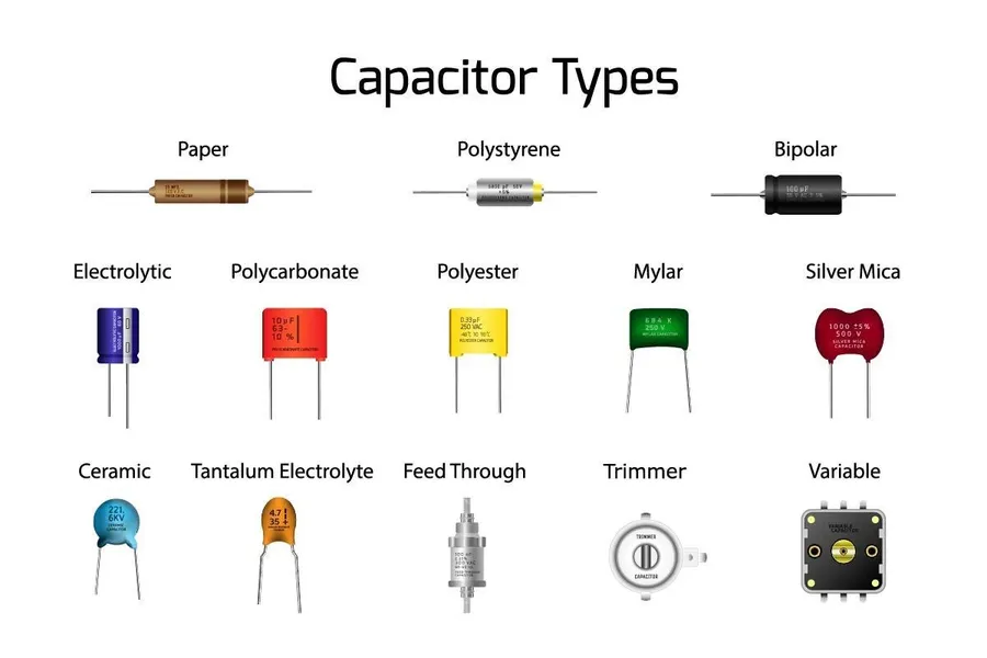
A capacitor is a fundamental passive electronic component that stores electrical energy within an electric field. This storage is achieved through the accumulation of electric charges on conductive plates, which are separated by a non-conductive material known as a dielectric. The capacitor's ability to store charge and release energy makes it essential in numerous electronic circuits and applications.
The basic structure of a capacitor consists of two conductive plates, typically metallic, that are positioned parallel to each other. These plates are separated by a dielectric material, which can be a variety of substances including air, ceramic, paper, or plastic. When a voltage is applied across the capacitor, an electric field forms between the plates, and this field is where the energy is stored. This stored energy can later be released by discharging the capacitor, typically into a load circuit.
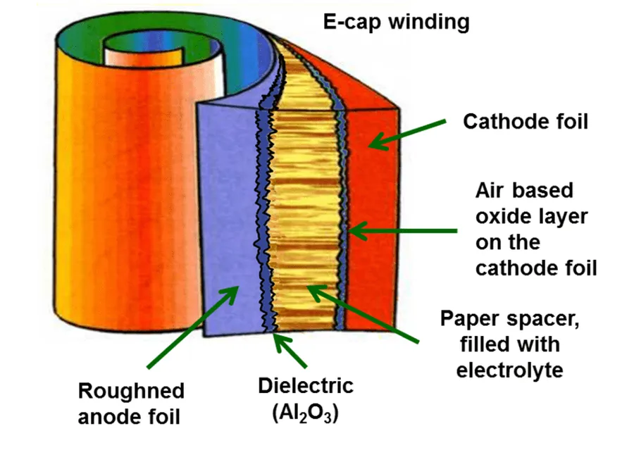
Capacitance, denoted by 'C', is a fundamental property of a capacitor, quantifying its ability to store electrical charge. It is measured in Farads (F), where one Farad is defined as one Coulomb of charge stored per one Volt of potential difference. The capacitance value is determined by the capacitor's physical characteristics, primarily the area of the conductive plates, the separation distance between them, and the permittivity of the dielectric material used as an insulator between the plates.
| Parameter | Symbol | Effect on Capacitance |
|---|---|---|
| Plate Area | A | Directly proportional: Increasing the plate area increases capacitance. |
| Plate Separation Distance | d | Inversely proportional: Increasing the distance decreases capacitance. |
| Permittivity of Dielectric | ε | Directly proportional: Increasing the permittivity increases capacitance. |
Mathematically, capacitance is expressed by the formula C = εA/d , where 'ε' represents the permittivity of the dielectric material, 'A' is the area of the plates, and 'd' is the distance separating the plates. The permittivity, often given as ε = εrε0, includes ε0, which is the permittivity of free space (approximately 8.854 x 10^-12 F/m), and εr is the relative permittivity (or dielectric constant) of the specific material used.
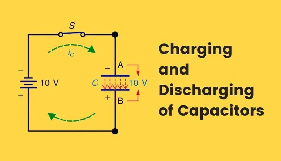
Capacitors store energy by accumulating electrical charges on their conductive plates when a voltage is applied across them. This charge separation establishes an electric field within the dielectric material, effectively storing electrical potential energy. This energy is not stored in the same way as chemical energy in a battery, but instead through the electric field.
The process of energy storage involves the migration of electrons. When connected to a voltage source, electrons flow from the negative terminal of the source to one plate of the capacitor, making it negatively charged. Simultaneously, electrons are drawn away from the other plate toward the positive terminal of the source, making that plate positively charged. This process continues until the voltage across the capacitor equals the source voltage, at which point the capacitor is considered fully charged.
The amount of energy a capacitor can store is determined by its capacitance and the voltage applied across it. The stored energy is released when a discharge path is provided, allowing the accumulated charges to flow through the circuit until the potential difference across the capacitor becomes zero.
| Process | Description |
|---|---|
| Charging | Electrons move to one plate, making it negatively charged, while electrons are drawn away from the other plate, making it positively charged. This creates an electric field and stores energy. |
| Discharging | Stored charge flows out of the capacitor through a circuit until the voltage across the capacitor is zero, releasing energy. |
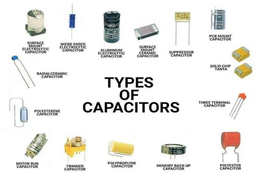
Capacitors are not monolithic devices; they come in a variety of types, each engineered with specific characteristics that make them suitable for different applications. The primary distinctions lie in their dielectric material, construction, and performance parameters, such as capacitance, voltage rating, and temperature stability. Understanding these differences is crucial for selecting the appropriate capacitor for a particular circuit or system design.
| Type of Capacitor | Dielectric Material | Typical Capacitance Range | Voltage Rating | Temperature Stability | Typical Applications |
|---|---|---|---|---|---|
| Ceramic Capacitors | Ceramic materials (e.g., barium titanate) | Picofarads to Microfarads | Low to high | Moderate | General-purpose, filtering, bypass, coupling |
| Electrolytic Capacitors | Aluminum oxide or tantalum oxide | Microfarads to Farads | Moderate to high | Poor to moderate | Power supplies, decoupling, energy storage |
| Film Capacitors | Polyester, polypropylene, or polystyrene films | Picofarads to Microfarads | Moderate to high | Good | High-frequency applications, audio, precision circuits |
| Supercapacitors (Ultracapacitors) | Porous carbon, metal oxides, conductive polymers | Farads to Kilofarads | Low | Good | Energy storage, backup power, regenerative braking |
| Tantalum Capacitors | Tantalum Pentoxide | Microfarads | Low to Moderate | Moderate to good | Portable electronics, high-reliability circuits |
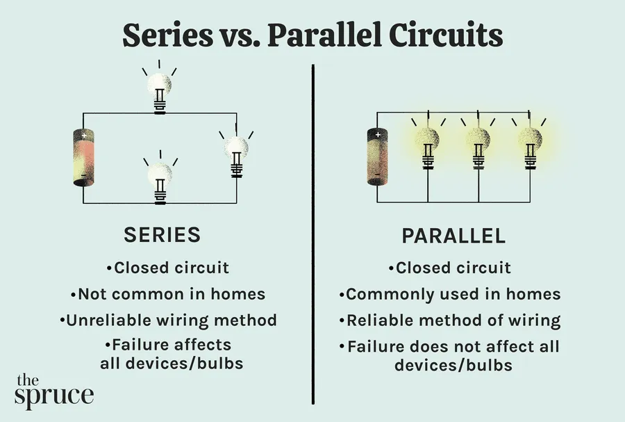
Capacitor configurations significantly impact circuit behavior. Connecting capacitors in series or parallel affects the total capacitance and voltage handling capabilities of the circuit, thus playing a vital role in circuit design.
| Configuration | Total Capacitance | Voltage Rating | Charge Storage |
|---|---|---|---|
| Series | Decreases (1/Ctotal = 1/C1 + 1/C2 + ...) | Increases | Same charge on each capacitor |
| Parallel | Increases (Ctotal = C1 + C2 + ...) | Same as the smallest capacitor | Total charge is the sum of individual capacitor charges |
These configurations are not merely theoretical concepts; they have a large impact on circuit design. For instance, putting capacitors in series can help create voltage dividers, while parallel connections can boost the capacity to store energy and increase the stability of the power system.
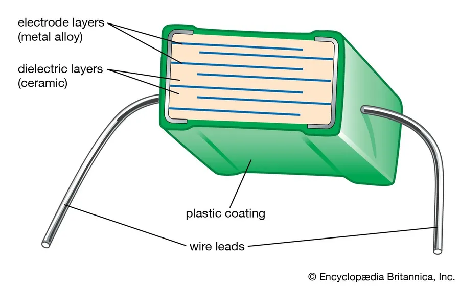
The dielectric material, an insulator positioned between the conductive plates of a capacitor, is paramount to its functionality and performance. This material is not merely a separator; it actively enhances the capacitor's ability to store energy by increasing its capacitance and voltage withstanding capabilities. The choice of dielectric significantly affects the capacitor's overall energy storage capacity, operational temperature range, and frequency response.
| Property | Role of Dielectric | Impact |
|---|---|---|
| Capacitance | Increases due to permittivity of dielectric | Higher energy storage per volt |
| Voltage Withstanding | Prevents electrical breakdown | Allows use at higher voltage potentials |
| Energy Storage | Enhanced by higher permittivity and voltage limits | Improved capability to store charge |
| Operational Temperature Range | Specific dielectric materials have different thermal stabilities | Wider usable range depending on material selection |
| Frequency Response | Different dielectric materials exhibit different frequency characteristics | Tailors performance to required operating frequencies |
Key parameters that are critical include the dielectric constant (or permittivity), the dielectric strength, and the loss tangent. The dielectric constant determines how much charge can be stored, the dielectric strength determines the maximum voltage it can sustain before breakdown, and the loss tangent relates to energy dissipation within the capacitor. The dielectric's impact is central to the capacitor's suitability for various applications.
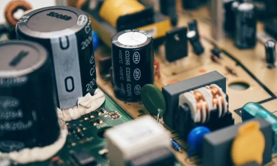
Capacitors, fundamental components in electrical and electronic circuits, exhibit remarkable versatility across a broad spectrum of applications. Their ability to store and release electrical energy makes them indispensable in numerous technologies, ranging from energy management to signal processing.
This section addresses common questions regarding capacitors, their functions, and applications in physics, providing clear and concise answers to enhance understanding.
Selecting the correct capacitor for a specific application is crucial for ensuring optimal circuit performance and longevity. This selection process hinges on understanding key capacitor specifications, including capacitance, voltage rating, tolerance, and temperature coefficient. Each specification plays a distinct role in the capacitor's performance under different operating conditions.
| Specification | Description | Importance |
|---|---|---|
| Capacitance | The ability of the capacitor to store an electrical charge, measured in Farads (F). | Determines the amount of energy the capacitor can store. It must match the application's requirements. |
| Voltage Rating | The maximum voltage that can be safely applied across the capacitor without risking damage. | Exceeding the voltage rating can lead to capacitor failure, dielectric breakdown, or reduced lifespan. |
| Tolerance | The permissible deviation of the actual capacitance value from its nominal (rated) value, often expressed as a percentage. | Affects the precision of the capacitor in timing and filtering applications. Tighter tolerance capacitors are used in precision circuits. |
| Temperature Coefficient | Describes how the capacitance changes with temperature variations, expressed in parts per million per degree Celsius (ppm/°C). | Crucial in temperature-sensitive applications where capacitance stability is paramount. Affects the capacitor’s performance in various operating environments. |
| Equivalent Series Resistance (ESR) | The internal resistance of the capacitor, which affects its ability to handle high-frequency signals. | Lower ESR values are preferred in high-frequency and high-current applications. High ESR can lead to energy loss. |
| Leakage Current | The small current that flows through the dielectric material of the capacitor when a voltage is applied. | Lower leakage current is required for low-power applications and energy-storage applications. High leakage current degrades performance in precision circuits. |
Understanding the mathematical relationships governing capacitors is crucial for circuit design and analysis. These formulas allow engineers to accurately determine a capacitor's behavior under various conditions, enabling precise control and optimization of electrical systems. This section presents the core formulas for calculating capacitance, charge, and stored energy in capacitors.
| Parameter | Symbol | Formula | Units |
|---|---|---|---|
| Capacitance | C | C = εA/d | Farads (F) |
| Charge | Q | Q = CV | Coulombs (C) |
| Energy Stored | U | U = 1/2 CV² or U = 1/2 QV or U= Q²/2C | Joules (J) |
Where: ε represents the permittivity of the dielectric material (ε = εrε₀, where εr is the relative permittivity and ε₀ is the permittivity of free space), A is the overlapping area of the capacitor plates, d is the distance between the capacitor plates, C is the capacitance, Q is the charge stored, and V is the voltage across the capacitor.
In conclusion, the capacitor, a fundamental component in physics, stands as an essential building block in the modern electronic world. Its ability to store electrical energy, and discharge it when needed, has a wide range of applications, from tuning circuits to powering electronic devices. By understanding the basic concepts of capacitance and its function in physics, and further exploring its applications, you can appreciate the importance of this often overlooked component in our daily lives and the innovative technologies that shape our future.

