
In the race to build smaller, more powerful IoT devices, the physical integration of communication modules has become a defining challenge for hardware engineers. Gone are the days when bulky pin-header connectors were the default; today's compact designs demand efficient, reliable, and high-performance mounting solutions. We explore how the shift toward castellated vertical mounting is revolutionizing PCB design and how it stacks up against the long-standing tradition of pin-header interfaces.
Understanding Castellated Hole Technology
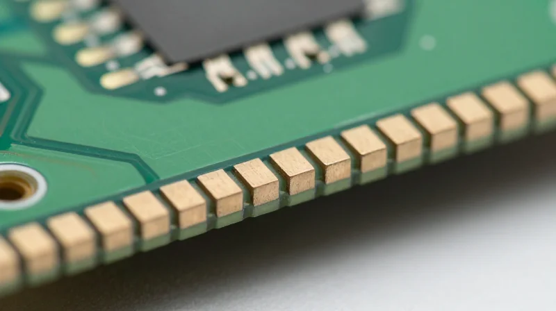
Defining Castellated Hole Technology
Castellated holes, also known as castellations, are semi-circular, plated holes located on the periphery of a printed circuit board (PCB). Unlike standard through-holes contained entirely within the board substrate, castellations are formed by drilling holes on the edge of the board profile and subsequently cutting through them. This exposes a conductive, plated surface that allows for surface-mount soldering directly to the board edge, effectively integrating one board assembly into another as if it were a component.
Fabrication and Manufacturing Process
The fabrication of castellations requires high-precision manufacturing to ensure the integrity of the plated surfaces. The process typically follows these steps: first, holes are drilled at the specified edge locations; second, the holes are plated with copper during the standard metallization process; finally, the board is routed or v-scored to expose the half-hole. Because the copper plating is exposed at the edge, maintaining a clean finish without burrs is essential for reliable electrical contact during assembly.
The Role of Castellated Holes in Hardware Design
Castellated holes transform a standalone PCB into a modular component, often used in radio frequency (RF) modules, Bluetooth modules, and complex micro-controllers. By eliminating the need for bulky headers, they allow for a lower profile and shorter signal paths, which is critical for high-speed communication systems where parasitic inductance must be minimized.
- Why are castellations preferred for RF modules?
Castellations allow for direct solder connections, which reduce signal degradation and parasitic impedance compared to standard pin-and-socket headers. - Are there specific PCB design rules for castellations?
Yes; designers must ensure adequate copper pad extensions beyond the board edge and consult with the fabricator regarding minimum hole size and plating thickness to prevent plating delamination during the routing process. - Can I use standard SMT reflow for these holes?
Yes, castellated edges are designed to be treated like any other surface-mount component pad during the standard SMT reflow oven process.
The Evolution of Traditional Pin-Header Interfaces
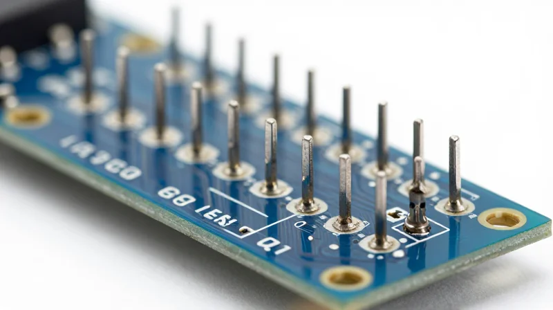
The Prototyping Legacy of Pin-Headers
For decades, the standard SMT and through-hole pin-header has been the bedrock of electronic modularity. These interfaces rely on a male-female friction-fit connection, allowing engineers to swap modules, debug signals, and iterate designs without the need for destructive rework. In the early stages of communication hardware development, this flexibility was invaluable for verifying RF front-ends and baseband processor integration.
Limitations in Modern Hardware Scaling
Despite their utility in lab environments, standard pin-headers introduce significant challenges when migrating to production-scale communication hardware. The mechanical footprint is bulky, necessitating high-profile connectors that prevent the stacking of thin PCBs. Furthermore, the parasitic inductance and capacitance associated with long pin-and-socket mating geometries can degrade high-speed signal integrity, making them unsuitable for modern microwave and high-frequency communication protocols.
| Feature | Traditional Pin-Headers | Production Constraints |
|---|---|---|
| Prototyping | High flexibility (solderless) | Requires connector footprint |
| Signal Integrity | Poor (high parasitic effects) | Impedance mismatch at high GHz |
| Z-Height | Significant | Blocks low-profile integration |
| Mechanical | Prone to vibration issues | Requires rigid mounting |
Frequently Asked Questions
- Why do pin-headers fail in high-vibration communication hardware?
The mechanical tolerance of pin-headers often leads to 'fretting' corrosion and intermittent contact loss when subjected to the thermal cycling or vibrations common in industrial communication modules. - Can pin-headers be used for RF signal routing?
Generally, no. The discontinuity introduced by the pin-and-socket interface creates impedance mismatches that lead to signal reflections, which are catastrophic for high-speed digital and RF performance.
Comparative Analysis: Space Optimization and Z-Height
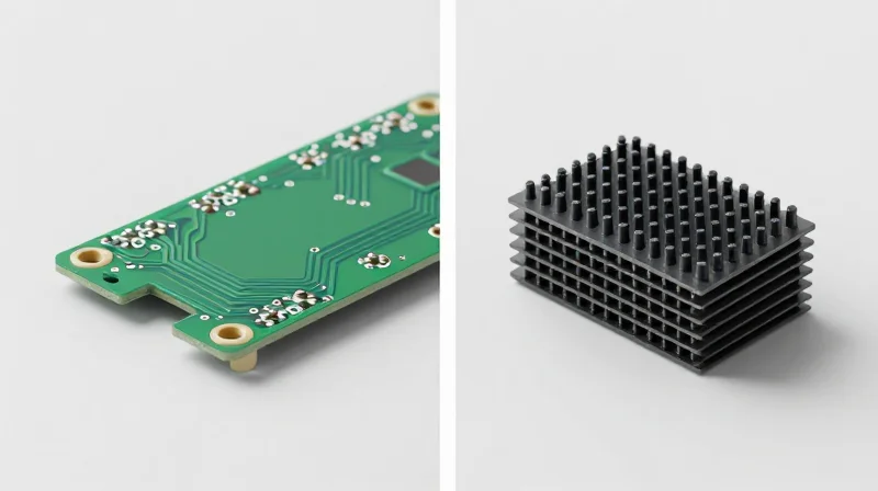
Minimizing Vertical Footprint
The primary mechanical advantage of castellated holes over standard SMT headers is the elimination of the vertical standoff. Traditional headers typically introduce a minimum of 2.0mm to 5.0mm of height to the assembly, which is often the limiting factor for enclosure design in modern ultra-slim communication hardware. Castellated technology allows components to be mounted flush against the base PCB, effectively reducing the height profile to the thickness of the component itself plus solder fillet height.
| Feature | Castellated Holes | Standard SMT Headers |
|---|---|---|
| Z-Height Profile | Near Zero (Flush) | High (2.0mm - 5.0mm+) |
| Mechanical Stability | High (Surface Solder) | Moderate (Leverage on Pins) |
| Board Footprint | Minimal (Edge-mounted) | Large (Grid required) |
| Vibration Resistance | Superior | Limited by Pin Flex |
Impact on Design Density
In space-constrained communication modules, the removal of bulky header connectors creates a ripple effect throughout the design. By adopting castellation, engineers can reduce the volume of the product chassis, improve airflow for thermal management, and increase the effective real estate on the primary PCB. This transition is essential for devices like IoT gateways or compact 5G signal boosters where every millimeter of vertical space is critical.
Comparative FAQs
- How much vertical space can I realistically save by switching to castellation?
Depending on the existing header pitch, you can expect to reclaim between 2mm and 6mm of vertical clearance, which is often enough to transition from a bulky aluminum chassis to a slim-line plastic housing. - Does the flush mounting of castellated parts affect heat dissipation?
Flush mounting improves thermal conduction directly into the PCB copper planes, acting as a heat sink; however, it removes the convective airflow gap provided by traditional standoff headers. - Is the mechanical stress distribution better with castellation?
Yes, castellated connections distribute shear forces across the entire solder fillet at the board edge, whereas headers concentrate stress on individual pins, making castellation more robust against impact and vibration.
RF Signal Integrity and Impedance Considerations

Impact of Interconnect Topology on Impedance Continuity
In high-frequency communication hardware, the transition between a daughterboard and a main PCB represents a significant point of potential signal degradation. Castellated holes offer a superior electrical path by providing a direct, low-profile solder joint that behaves closer to a surface-mount transmission line. Conversely, standard SMT headers introduce physical separation and mechanical pins, creating a lumped-element discontinuity that frequently results in impedance mismatch, signal reflections, and undesirable radiated EMI.
Comparative Parasitic Characteristics
| Parameter | Castellated Holes | Standard SMT Headers |
|---|---|---|
| Parasitic Inductance | Low (Integrated path) | High (Vertical pin length) |
| Capacitive Coupling | Minimal | Significant (Between pins) |
| Impedance Control | Excellent at high GHz | Limited due to geometry |
| EMI Radiation | Low (Controlled edge) | High (Loop antenna effect) |
RF Performance FAQ
- Why do standard headers perform poorly at frequencies above 2GHz?
The vertical length of the pins acts as an inductive stub, while the gaps between pins introduce parasitic capacitance, disrupting the 50-ohm characteristic impedance required for optimal RF signal propagation. - How do castellated holes mitigate signal reflection?
Castellated connections shorten the signal path and minimize the geometry change at the solder junction, allowing for a more consistent transmission line profile compared to the multi-part interface of a pin header. - Does the solder meniscus in a castellated hole affect performance?
While the solder volume can cause minor local impedance variations, careful pad design and consistent reflow profiles allow this to be modeled as a controlled discontinuity, far superior to the chaotic parasitics of a pin-and-socket connection.
Manufacturing Efficiency and Assembly Throughput
Optimizing Throughput in SMT Assembly
The integration of castellated modules represents a significant shift in manufacturing philosophy, moving from complex multi-stage assembly to high-speed, automated reflow soldering. By eliminating mechanical headers, manufacturers can leverage standard Pick-and-Place (P&P) equipment to handle modules as surface-mount components, dramatically increasing units-per-hour (UPH) metrics.
| Feature | SMT Header Assembly | Castellated Module Assembly |
|---|---|---|
| Placement Method | Manual or Specialized Robotics | Standard High-Speed SMT P&P |
| Soldering Process | Selective or Wave Soldering | Full-Board Reflow |
| Labor Intensity | High (Manual handling required) | Low (Fully automated) |
| Inspection | Visual/X-Ray (Pins hidden) | Automated Optical Inspection (AOI) |
Reducing Manual Labor and Process Latency
Standard SMT headers often require post-process soldering, such as selective or hand-soldering, which creates a process bottleneck and introduces human-variable error. Castellated holes allow the module to be treated as a standard SMD, enabling the entire assembly to traverse the reflow oven in a single pass. This consolidation reduces handling, minimizes floor space requirements, and drastically cuts down on the Total Cost of Ownership (TCO) for communication hardware.
Frequently Asked Questions
- Does switching to castellated modules require new P&P nozzles?
Generally, no. Standard vacuum nozzles used for typical surface-mount packages are compatible with castellated modules, provided the module weight and center of gravity are within the machine's payload specifications. - How is solder joint inspection handled for castellated holes?
Castellated holes are ideal for Automated Optical Inspection (AOI). Because the solder fillets are exposed on the outer edge of the PCB, AOI systems can easily confirm wetting and fillet formation, unlike hidden headers that often necessitate expensive X-ray analysis. - What is the primary impact on overall assembly cycle time?
By aligning the module with the main board's SMT reflow schedule, the need for secondary manual assembly stations is eliminated, effectively reducing the cycle time per board by 15–30% depending on the volume and complexity of the header count.
Mechanical Durability and Vibration Resilience
Mechanical Integrity of Interconnect Systems
In ruggedized or mobile communication environments, the mechanical stability of an interconnect is as critical as its electrical performance. Standard SMT headers, which rely on cantilevered pin contacts, often introduce structural vulnerabilities when subjected to high-g shocks or continuous vibrational fatigue. Castellated holes, by contrast, facilitate a surface-mount metallurgical bond that effectively anchors the module directly to the host PCB, creating a rigid interface that minimizes sheer stress on individual solder joints.
| Feature | Castellated Holes | SMT Pin-Headers |
|---|---|---|
| Mechanical Bond | Metallurgical (Direct Solder) | Elastic (Mechanical Contact) |
| Vibration Resistance | High (Low mass, rigid) | Moderate (Prone to resonance) |
| Failure Mode | Solder fatigue after cycle | Pin displacement/Intermittent contact |
| PCB Footprint | Low profile, flush | High profile, standoff |
Vibration Resilience and Fatigue Analysis
Vibrational stress is the primary cause of intermittent connectivity in dense hardware designs. Because SMT headers introduce a vertical offset (standoff height), they create a lever arm effect during vibration. Even micro-vibrations can lead to 'fretting corrosion' on gold-plated header pins. Castellated joints eliminate this lever arm entirely by maintaining a zero-clearance interface, significantly enhancing the resonance frequency of the assembly and preventing the mechanical degradation common in modular systems.
- Why do pin-headers fail under vibration?
The cantilevered nature of header pins makes them susceptible to mechanical resonance, which can cause micro-gaps and intermittent electrical noise during high-acceleration events. - How do castellated holes mitigate solder stress?
The concave plating structure increases the surface area for solder fillets, allowing the joint to distribute physical loads more uniformly across the host PCB pad. - Are there limits to castellated reliability?
While inherently more stable, castellated joints are less tolerant of extreme thermal expansion mismatches between different PCB substrates, necessitating careful CTE matching in harsh environments.
Cost-Benefit Analysis for Product Scaling
Evaluating the financial viability of castellated holes versus SMT headers requires a total cost of ownership (TCO) approach that extends beyond simple unit pricing. While castellated modules often command higher PCB fabrication fees due to specialized edge-milling processes, they frequently achieve net savings by eliminating external connector components and reducing secondary assembly steps.
Comparative Cost Matrix
| Cost Driver | Castellated Holes | SMT Headers |
|---|---|---|
| PCB Fabrication | High (Requires half-hole milling) | Low (Standard processing) |
| Component BOM | Zero (integrated) | Medium (Header + pins) |
| Assembly Labor | Low (Single reflow pass) | High (Manual or secondary SMT) |
| Test/Rework | Complex (Requires X-ray) | Standard (Visual inspection) |
Strategic Financial Considerations
When scaling production for high-volume communication hardware, the 'hidden' costs of headers—such as inventory management for multiple SKUs and increased assembly cycle time—often outweigh the initial PCB fabrication surcharge. Castellated designs consolidate the bill of materials, effectively reducing supply chain overhead and simplifying the pick-and-place programming logic.
Frequently Asked Questions
- At what production volume does castellated design become more cost-effective?
Generally, as production moves beyond prototype stages (1,000+ units), the labor savings from eliminating manual header placement and the reduction in connector logistics cost usually offset the per-board fabrication premium. - Does the complexity of testing castellated joints add significant cost?
Yes, it can. Because solder joints under a castellation are difficult to inspect visually, designers often incur costs related to automated optical inspection (AOI) programming or X-ray verification to ensure reliability. - Is there a trade-off in design flexibility?
SMT headers offer superior modularity and easy field-serviceability. Choosing castellated holes locks the design into a permanent solder connection, which may increase costs associated with board-level repairs or field maintenance.
Choosing the Right Interface for Your Application

Choosing the correct interface is rarely about a single metric; it requires a holistic review of your product's mechanical requirements, assembly throughput, and target market. While castellated holes offer a flush, low-profile footprint, SMT pin-headers provide modularity that is often superior for rapid prototyping and field servicing.
Decision Matrix for Interface Selection
| Requirement | Preferred Interface | Reasoning |
|---|---|---|
| Extreme Space Constraints | Castellated | Eliminates connector housing height and footprint. |
| Field Serviceability | SMT Headers | Allows for non-destructive module removal. |
| High Vibration/Shock | Castellated | Direct solder creates a rigid, low-mass bond. |
| Cost of Assembly | SMT Headers | Reduces complex board edge plating requirements. |
Frequently Asked Questions
- Can I easily rework castellated modules?
Reworking castellated connections is significantly more difficult than traditional headers, often requiring hot-air stations and risking damage to the module's edge pads. - Does the castellated mounting method increase PCB fabrication costs?
Yes, castellated holes require extra plating and routing steps at the PCB board edge, which can add a premium to small-batch production costs. - When is an SMT header objectively better?
When your design requires modularity, such as a plug-and-play radio module or an upgradeable processing board, SMT headers are the industry standard for maintainability.
Ultimately, if your hardware design prioritizes a 'set-and-forget' compact architecture, castellated mounting is the superior choice. However, if your communication hardware requires iterative updates or modular maintenance in the field, the slight space penalty of SMT headers is a wise investment in operational flexibility.
While traditional pin-headers remain a staple for low-volume prototyping and modular versatility, the industry's clear migration toward castellated technology is driven by the undeniable necessity for smaller, high-performance RF hardware. By reducing impedance, lowering height profiles, and streamlining assembly, castellated modules offer a superior path for modern consumer and industrial electronics. If you are ready to optimize your next design, contact our engineering team to review your schematic and determine the best mounting strategy for your specific hardware architecture.
