
Wind turbine environments are among the most unforgiving in the industrial world, subjecting sensitive electronics to constant thermal cycling, extreme vibration, and moisture ingress. As a design engineer, your choice of PCB determines the difference between 25 years of field reliability and premature system failure. This guide outlines the rigorous selection process required for mission-critical wind energy control systems.
Understanding the Operational Environment
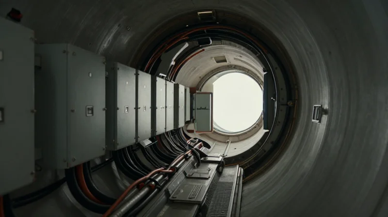
Navigating Environmental Stressors in Nacelle Environments
The nacelle of a wind turbine is a hostile environment that pushes standard electronic components to their physical limits. Unlike stationary industrial environments, wind turbines operate under dynamic, unpredictable conditions where vibration, humidity, and temperature shifts converge to accelerate material fatigue and dielectric breakdown.
| Stress Factor | Primary PCB Impact | Recommended Mitigation |
|---|---|---|
| Thermal Cycling | CTE Mismatch/Solder Fatigue | High-Tg Substrates |
| Salt/Moisture Ingress | Electrochemical Migration | Conformal Coating/Parylene |
| High-Frequency Vibration | Fatigue Cracking | Advanced Rigid-Flex/Damping |
Critical Environmental Considerations
- Why is thermal cycling a primary cause of failure?
Rapid transitions between ambient exterior temperatures and heat generated by internal power conversion create significant mechanical stress on vias and solder joints due to Coefficient of Thermal Expansion (CTE) mismatches. - How does coastal deployment affect electronics?
Offshore and near-shore installations expose components to salt spray and high humidity, which facilitate dendritic growth and conductive path formation, leading to catastrophic short circuits. - What role does vibration play in long-term reliability?
Constant rotational kinetic energy translates into structural vibration, which can fatigue PCB interconnects and loosen heavy surface-mount components, necessitating vibration-resistant mounting and reinforced trace routing.
Engineers must prioritize materials with high glass transition temperatures (Tg) and robust chemical resistance. In the context of high-reliability wind turbine control, selecting a substrate that minimizes dielectric loss while maintaining mechanical rigidity is essential for surviving the decades-long service life mandated by modern renewable infrastructure standards.
Material Selection: Beyond Standard FR-4
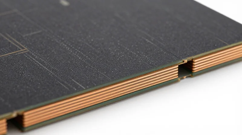
Standard FR-4, while cost-effective for consumer electronics, often fails under the cyclical mechanical stress and extreme thermal variations found in wind turbine nacelles. For high-reliability applications, engineers must pivot toward high-Tg (glass transition temperature) laminates and specialized thermally conductive substrates to prevent delamination, board warping, and signal degradation over a 20-year operational lifecycle.
The Role of High-Tg Laminates
High-Tg materials provide superior dimensional stability at elevated temperatures compared to standard FR-4 (typically ~130°C). By utilizing materials with a Tg exceeding 170°C, design engineers can ensure that the coefficient of thermal expansion (CTE) remains controlled during the rapid power fluctuations inherent in wind energy generation. This stability is critical for preserving the structural integrity of micro-vias and plated through-holes.
Material Performance Comparison
| Material Type | Typical Tg (°C) | Thermal Conductivity | Best Use Case |
|---|---|---|---|
| Standard FR-4 | 130-140 | Low | Non-critical indoor sensors |
| High-Tg Epoxy | 170-180 | Moderate | Standard control units |
| Polyimide | 250+ | Moderate | Extreme thermal cycling |
| Metal Core (IMS) | N/A | High | Power conversion modules |
Thermally Conductive Substrates
In power electronics for turbine control, heat dissipation is as vital as structural integrity. Metal Core Printed Circuit Boards (MCPCBs), particularly aluminum or copper-based substrates, act as a heat sink integrated directly into the board. This facilitates efficient heat transfer from high-power MOSFETs and IGBTs to the chassis, significantly extending the mean time between failures (MTBF).
Common Engineering Questions
- Why is CTE (Coefficient of Thermal Expansion) so critical in turbines?
Turbines undergo massive temperature swings; if the PCB expands at a different rate than the components, it creates shear stress on solder joints, leading to cracked connections. - Is moisture absorption a factor in laminate choice?
Yes, high-reliability laminates are engineered with lower moisture absorption rates to prevent dielectric breakdown and conductive anodic filament (CAF) growth in high-humidity offshore environments.
Managing Thermal Dissipation and Heat Sinking
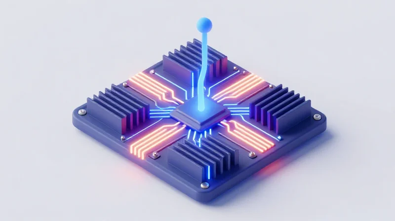
In the confined, non-ventilated enclosures characteristic of wind turbine nacelle control cabinets, heat dissipation becomes the primary constraint on system longevity. When ambient cooling is unavailable, the PCB must function as the primary heat spreader, utilizing thermal vias, copper planes, and specialized substrates to mitigate the risks of localized hotspot formation and thermal fatigue.
Substrate and Layer Stack-up Strategies
Standard FR-4 laminates frequently fail under the sustained thermal cycling of turbine operations. To manage high power density, designers must transition to high-Tg materials or metal-core PCBs (MCPCBs). Aluminum-based substrates significantly improve heat transfer away from high-power IGBTs and MOSFETs by providing a direct thermal path to the chassis.
| Material Type | Thermal Conductivity (W/mK) | Primary Application |
|---|---|---|
| Standard FR-4 | 0.25 - 0.35 | Low-power logic control |
| High-Tg FR-4 | 0.40 - 0.50 | General power regulation |
| MCPCB (Aluminum) | 1.0 - 3.0 | High-density power electronics |
| Ceramic-Filled Laminate | 2.0 - 5.0 | RF and extreme heat zones |
Advanced Heat Dissipation Techniques
- Thermal Via Arrays
Implementing high-density thermal via stitching directly under power components allows for effective heat migration into internal copper ground planes, which act as secondary heatsinks. - Copper Weight Optimization
Using heavier copper foils (typically 2oz to 4oz) on inner power layers reduces I2R losses, significantly lowering the total heat generated during high-current operations. - Phase-Change Interface Materials
Utilizing phase-change thermal interface materials (TIM) between the PCB and the enclosure wall provides superior contact reliability despite vibrations and thermal expansion cycles.
Design Considerations for Sealed Cabinets
When convection is not an option, conduction is the only reliable path. Engineers must perform exhaustive thermal simulation during the layout phase to identify hotspots. Placing high-dissipation components at the perimeter of the board—closer to the thermally conductive enclosure mounting points—can drop junction temperatures by as much as 15% compared to center-board placement.
Designing for Extreme Vibration and Mechanical Stress
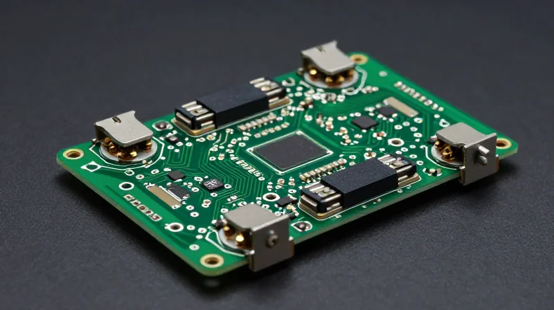
Wind turbine nacelles are environments defined by non-stop mechanical agitation. Beyond electrical performance, the PCB architecture must act as a structural member capable of damping micro-strains. Failure to account for the resonant frequencies of large power components and connectors leads to solder fatigue and copper trace delamination over time. Engineering for this environment requires a departure from standard desktop-grade mounting, favoring techniques that prioritize mechanical load distribution.
Board Stiffening and Structural Integration
Large-format boards often flex under cyclical stress, placing undue pressure on surface-mount joints. To mitigate this, engineers should employ strategic stiffeners—typically metallic rails or high-modulus composite bars—fixed to the board edges. Furthermore, optimizing the PCB stack-up to include balanced copper distribution reduces internal stress concentrations, which minimizes the tendency for the board to warp during thermal cycling.
Component Placement and Solder Integrity
| Stress Factor | Design Mitigation Strategy | Reliability Impact |
|---|---|---|
| Component Mass | Under-filling of BGA/QFN | Reduces shear stress on pads |
| Cyclical Vibration | Conformal coating (thick) | Dampens mechanical resonance |
| Flexure Stress | Keep-out zones near edges | Prevents trace fracture |
- How does under-filling impact solder reliability?
Under-filling distributes the coefficient of thermal expansion (CTE) mismatch and mechanical shock loads across the entire underside of a component, rather than concentrating stress solely on the solder joints. - Is standard surface mounting sufficient for heavy components?
For heavy power components like large inductors or transformers, surface mounting alone is insufficient; through-hole mounting with mechanical staking or epoxy bonding is required to prevent detachment during vibration events. - Why is trace routing critical in high-vibration areas?
Traces should be routed with generous fillets and avoided near board mounting holes, as these areas experience the highest strain concentrations during chassis deformation.
// Recommended design rule for high-stress connectors
connector_keepout_radius = 5.0mm; // Distance from board edge/mounting hole
via_plating_thickness_min = 25um; // Essential for high-vibration barrel fatigue
solder_alloy = SAC305_High_Reliability_Doped; // Alloy for enhanced ductility
Corrosion Mitigation and Protective Coatings
Atmospheric Corrosion Resilience in Wind Turbines
Wind turbine nacelles are notorious for inducing accelerated material degradation through high humidity, salinity, and potential airborne pollutants. To prevent trace oxidation and electrochemical migration, engineers must implement a multi-layered defense strategy that starts at the board finish level and extends to total encapsulation.
| Surface Finish | Corrosion Resistance | Best Use Case |
|---|---|---|
| ENIG | High | General high-reliability control circuits. |
| ENEPIG | Excellent | High-vibration modules requiring robust solder joints. |
| Immersion Silver | Low | Unsuitable for high-sulfur/salt environments. |
Selecting Protective Barriers: Coatings vs. Potting
The choice between conformal coating and potting depends on the degree of mechanical shock and the exposure intensity. Conformal coatings, such as Parylene or silicone, provide a lightweight shield against condensation. Potting compounds offer superior structural reinforcement and environmental hermeticity but add significant thermal mass.
- Why is ENEPIG preferred over ENIG for turbine control?
ENEPIG (Electroless Nickel Electroless Palladium Immersion Gold) provides a superior barrier against black pad syndrome and oxidation in high-vibration, high-humidity environments compared to standard ENIG. - When should potting be used over coating?
Potting is required when the assembly is subjected to extreme vibration or potential direct liquid ingress, as it provides a monolithic protective block around components that a thin coating cannot match. - Does conformal coating affect thermal management?
Yes, heavy application of thick coatings can act as an insulating blanket, potentially elevating component junction temperatures; therefore, thermal-conductive coatings should be evaluated for high-power density sections.
Design Best Practices
To ensure coating efficacy, maintain a strict keep-out zone around connectors to prevent wicking. Furthermore, perform salt-fog testing (ASTM B117) on representative board assemblies to validate that the chosen material chemistry remains chemically inert throughout the expected service life of the turbine.
Navigating IEC 61400 Compliance Standards
The Role of IEC 61400 in Electronic System Integrity
IEC 61400 serves as the global benchmark for wind energy conversion systems. For engineers, compliance is not merely about meeting performance targets but about rigorous verification of durability under environmental and electrical stressors. Designing PCB assemblies that comply with these standards involves rigorous stress testing, thermal validation, and electromagnetic compatibility (EMC) assessments tailored for the harsh conditions inherent in wind energy infrastructure.
Key Certification Standards for PCB Reliability
| Standard | Focus Area | PCB Implication |
|---|---|---|
| IEC 61400-1 | Design Requirements | Governs safety margins and control system fault tolerance. |
| IEC 61400-21 | Power Quality | Requires low EMI emissions to protect grid stability. |
| IEC 61400-25 | Communications | Mandates protocol consistency for monitoring hardware. |
Frequently Asked Questions Regarding Compliance
- How does IEC 61400 affect component selection?
The standard dictates that only components with documented derating factors and reliability profiles (such as MTBF data) should be used, ensuring the assembly can handle the ambient temperature fluctuations found in nacelle environments. - Is EMC testing mandatory for turbine PCBs?
Yes, electromagnetic compatibility is critical. PCBs must be designed with strict stack-up control and shielding to comply with IEC 61400-21, ensuring the turbine does not disrupt grid-side communication or site-wide sensor networks. - Why is traceability required for certification?
Traceability is mandated by IEC 61400 to verify that every PCB layer, material, and component lot meets specific quality grades (e.g., IPC Class 3), which is essential for forensic analysis if a failure occurs in the field.
To streamline certification, engineers should implement design-for-compliance (DFC) early in the development cycle. This includes utilizing simulation software for thermal analysis and signal integrity early on, ensuring that the final hardware passes the rigorous environmental stress screening (ESS) required for IEC validation.
Testing and Quality Assurance Protocols

Validating Endurance Through HALT and HASS
For wind turbine control systems, standard reliability testing is often insufficient to capture latent defects that only manifest under extreme conditions. Highly Accelerated Life Testing (HALT) and Highly Accelerated Stress Screening (HASS) are critical methodologies for identifying failure modes related to thermal cycling, vibration, and extreme operating stresses. By applying these methods during the design and production validation phases, engineers can push the PCB beyond its nominal operating envelope to uncover design margins and manufacturing inconsistencies before they cause catastrophic failure in the field.
| Methodology | Primary Goal | Implementation Stage | Stress Level |
|---|---|---|---|
| HALT | Identify design weaknesses | Prototype/Design Phase | Destructive (Extreme) |
| HASS | Screen manufacturing defects | Production/Manufacturing | Non-destructive (Optimized) |
Essential QA Protocols for Turbine Electronics
Quality assurance for high-reliability boards requires a multi-layered approach that integrates non-destructive testing with automated inspection to maintain strict adherence to IPC class-3 standards.
- What role does X-Ray Inspection (AXI) play?
Automated X-Ray Inspection is mandatory for BGA and CSP components to detect hidden solder joint voids or bridging that optical inspection cannot identify. - Why is Thermal Cycling critical?
Wind turbines experience significant diurnal temperature swings; cycling PCBs between -40°C and +85°C validates the integrity of solder joints and prevents CTE (Coefficient of Thermal Expansion) mismatch failures. - How does Flying Probe testing compare to ICT?
Flying probe is ideal for prototype testing and small production runs due to its flexibility, while In-Circuit Testing (ICT) is preferred for high-volume manufacturing to ensure rapid, consistent electrical validation.
Ultimately, the shift from reactive troubleshooting to predictive testing protocols significantly reduces the total cost of ownership. By incorporating HALT/HASS into the procurement and QA process, operators ensure that control system electronics maintain integrity for the intended 20-to-25-year turbine lifespan.
Strategic Lifecycle Management
Mitigating Component Obsolescence
Wind turbine control systems frequently operate for 20 to 25 years, far exceeding the typical lifecycle of standard industrial electronic components. Engineers must adopt a design-for-longevity approach that prioritizes components with robust manufacturer roadmaps, active EOL (End-of-Life) notifications, and long-term availability guarantees. Reliance on consumer-grade silicon is a critical failure mode; instead, specify automotive or industrial-grade ICs that carry extended lifecycle support.
Supply Chain Resilience Strategies
| Strategy | Risk Reduction Impact | Implementation Effort |
|---|---|---|
| Component Standardization | High | Moderate |
| Last-Time Buy (LTB) | Medium | Low |
| Design Agnostic Footprints | High | High |
Frequently Asked Questions on Lifecycle Management
- How do I handle obsolete components during a 20-year cycle?
Employ a proactive obsolescence monitoring service and maintain a controlled inventory of critical-path silicon through strategic Last-Time Buy agreements. - Why should I avoid custom ASICs in turbine control?
While efficient, custom ASICs are single-source risks. If the fabricator discontinues the line, the entire turbine controller architecture may require a costly, high-risk redesign. - What role does the BOM play in lifecycle health?
A healthy Bill of Materials (BOM) is audited annually for component risk scores, including manufacturer stability, regional sourcing dependency, and lead-time volatility.
Selecting the right PCB for wind energy is a multifaceted challenge that requires prioritizing resilience over cost-cutting. By adhering to strict thermal management and material standards, engineers can ensure long-term operational success in the field. Ready to integrate high-reliability electronics into your next wind project? Contact our engineering team today for a consultation on your specific application requirements.
