
In the fast-paced world of electric vehicle production, the reliability of your Battery Management System (BMS) is non-negotiable. As automotive standards tighten and production timelines accelerate, selecting a PCB partner who can balance rigorous safety engineering with industrial-scale output is the single most critical decision for your supply chain. This guide provides the expert framework needed to evaluate, vet, and partner with the right high-reliability PCB manufacturer.
Understanding the High Stakes of Automotive-Grade PCBs
The Engineering Challenge: Beyond Standard Consumer Electronics
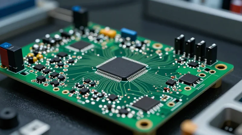
The transition from consumer-grade to automotive-grade electronics is not merely a matter of material selection but a fundamental shift in reliability engineering. In an Electric Vehicle (EV) Battery Management System (BMS), the PCB serves as the critical nervous system, tasked with monitoring thousands of individual cell voltages and temperatures while managing active balancing. Standard commercial PCBs often rely on base materials and manufacturing processes that cannot withstand the long-term degradation mechanisms prevalent in automotive operation, such as Coefficient of Thermal Expansion (CTE) mismatch, high-frequency vibration, and transient chemical exposure.
Key Environmental Stress Factors
| Stress Factor | Commercial Grade Impact | Automotive Grade Requirement |
|---|---|---|
| Thermal Cycling | Delamination and via cracking | High Tg materials; >2000 cycles |
| Vibration | Solder joint fatigue | AEC-Q200 qualification; IPC-Class 3 |
| Humidity/Chemical | Dendritic growth/corrosion | Advanced conformal coating; CAF resistance |
Frequently Asked Questions
- Why is standard FR-4 inadequate for BMS applications?
Standard FR-4 lacks the thermal stability required to withstand the rapid heating and cooling cycles of an EV. Over time, the internal stress leads to via barrel cracking, resulting in intermittent connectivity and potential system failure. - What is the importance of CAF resistance?
Conductive Anodic Filament (CAF) growth is a microscopic metallic short circuit caused by moisture and voltage. Automotive-grade PCBs require specialized resins that prevent these filaments from forming between conductors under high voltage bias. - How does PCB manufacturing impact functional safety (ISO 26262)?
Manufacturing defects in a BMS, such as trace thinning or inconsistent plating, directly impede the system's ability to reach necessary ASIL (Automotive Safety Integrity Level) ratings, increasing the risk of catastrophic battery thermal events.
The ISO 26262 Benchmark: Verifying Compliance and Safety
Why ISO 26262 is the Pillar of EV Safety
ISO 26262 serves as the international standard for functional safety of road vehicles, providing a framework that minimizes the risk of systematic and random hardware failures. For Battery Management Systems (BMS), where failure can result in catastrophic thermal events, the standard dictates the entire lifecycle—from conceptual design to manufacturing processes. A PCB manufacturer must demonstrate that their production environment supports the traceability and quality requirements demanded by the ASIL rating of your specific battery architecture.
Evaluating Manufacturer Certification Documentation
When auditing a potential partner, look beyond simple ISO 9001 certifications. You must verify that the manufacturer maintains a rigorous 'Quality Management System' specifically tailored for the automotive industry, typically signified by IATF 16949. Requesting specific proof of their ability to maintain process consistency is essential to meeting the stringent requirements of ISO 26262.
| Certification/Standard | Purpose in BMS Manufacturing | ISO 26262 Correlation |
|---|---|---|
| IATF 16949 | Automotive quality management | Foundational requirement for process consistency. |
| IPC-6012 Class 3 | High-reliability performance | Ensures board integrity under harsh conditions. |
| ISO 26262 | Functional safety lifecycle | The governing mandate for system-level safety. |
Frequently Asked Questions
- Does the PCB manufacturer need to be ISO 26262 certified?
While ISO 26262 is a system-level standard, manufacturers must provide 'qualified' components or processes that contribute to the system's safety goal. They must be able to document their ability to meet the strict quality standards required to support your compliance. - What is the role of traceability in this context?
Traceability allows you to track materials and manufacturing steps back to the source. In the event of a field failure, this documentation is essential for performing a Root Cause Analysis, which is a core requirement of ISO 26262 safety audits. - Is IPC Class 3 enough for automotive boards?
IPC Class 3 is a minimum requirement for mission-critical hardware, but for EV battery systems, it must be paired with automotive-specific quality management (IATF 16949) to ensure long-term survivability.
Advanced Materials Engineering for Thermal Management

Advanced Materials Engineering for Thermal Management
In the context of EV Battery Management Systems, the PCB acts as a vital heat sink and power distribution platform. Choosing a manufacturer capable of managing high-glass transition temperature (TG) materials and heavy copper architectures is non-negotiable, as these elements prevent board delamination and thermal runaway during the intensive charge-discharge cycles characteristic of electric mobility.
Critical Material Selection for Thermal Reliability
| Material Type | Primary Benefit | Typical BMS Application |
|---|---|---|
| High-TG FR-4 | Superior thermal stability | Standard control units |
| IMS/Metal-Core PCB | Direct heat dissipation | High-current power stages |
| Ceramic Substrates | Exceptional thermal conductivity | High-voltage isolation layers |
Beyond selecting the right dielectric, the physical construction of the board must accommodate significant thermal expansion. A qualified manufacturer must demonstrate expertise in heavy copper manufacturing—often 3oz to 6oz copper weights—which ensures the BMS can handle continuous high-amperage loads without exceeding operating temperature limits.
Frequently Asked Questions on Thermal Engineering
- Why is a high Glass Transition Temperature (TG) material essential for BMS?
A high TG ensures the substrate remains rigid and resists chemical degradation when exposed to constant thermal cycling and high ambient temperatures found in EV battery packs. - How does heavy copper thickness influence BMS safety?
Increased copper weight reduces the electrical resistance of the circuit, which significantly lowers Joule heating, effectively mitigating the risk of board-level heat failure under high-current scenarios. - What should I look for when auditing a manufacturer's thermal management capabilities?
Audit their process for handling specialized laminates, documentation of thermal stress testing (such as IST testing), and their history of manufacturing multi-layer boards with varying copper weights on internal layers.
Supply Chain Transparency and Traceability
The Imperative of Traceability in EV Battery Management Systems
For high-reliability BMS applications, traceability is not merely a logistical convenience; it is a fundamental pillar of automotive functional safety and liability management. In the event of a field failure or safety recall, the ability to pinpoint the exact batch of raw materials, laminate suppliers, and individual component lots is essential for root-cause analysis and localized remediation. A manufacturer without robust traceability exposes the OEM to immense regulatory risk and catastrophic brand damage.
Key Components of a Transparent Supply Chain
| Category | Traceability Metric | Verification Requirement |
|---|---|---|
| Raw Laminates | Batch/Date Code | Certificate of Conformance (CoC) |
| Passive Components | Distributor Origin | Anti-Counterfeit Documentation |
| Process Chemicals | Vendor Batch Control | Material Safety Data Sheets (MSDS) |
| PCB Assembly | Automated Optical Inspection (AOI) Logs | Serialized Board Histories |
Auditing Your Manufacturing Partner
Evaluating a PCB partner requires looking beyond standard ISO certifications. You must audit their internal data management systems and their willingness to share supply chain transparency. A credible manufacturer should demonstrate full visibility into their Tier 2 and Tier 3 suppliers, ensuring that quality standards are upheld upstream.
- How far back should traceability extend?
A high-reliability partner should provide 'cradle-to-gate' traceability, covering everything from the raw fiberglass and resin batches to the specific assembly shift on the production floor. - Why is component sourcing transparency critical?
Unauthorized component distributors are a significant source of counterfeit parts. Transparency ensures that every component is sourced through franchised, verified channels, maintaining compliance with automotive quality standards. - What tools demonstrate effective traceability?
Look for manufacturers utilizing integrated ERP systems that link serialized PCB identifiers with raw material batch numbers, allowing for digital 'birth certificates' for every board produced.
Assessing Scalability: From Prototype to Mass Production

Scalability Assessment: Bridging the Gap
The primary risk in moving to mass production is the 'quality drift' that occurs when manufacturing processes are not adequately controlled or scaled. A partner for high-reliability EV BMS must demonstrate an infrastructure that allows for a seamless transition from quick-turn prototype fabrication to full-scale automotive assembly lines.
Comparison of Production Capability Metrics
| Feature | Prototype Focus | Mass Production Focus |
|---|---|---|
| Tooling | Soft tooling, laser direct imaging | Hard tooling, optimized panelization |
| Quality Control | Spot inspection | Automated Optical Inspection (AOI) + In-Circuit Testing (ICT) |
| Supply Chain | Available inventory | Strategic stocking and life-cycle management |
| Throughput | Flexibility for design changes | High-volume efficiency and consistency |
Key Questions for Manufacturing Scalability
- Does the manufacturer support NPI to volume transfer?
Ensure they have a dedicated New Product Introduction (NPI) team that works alongside the production engineering department to prevent design-for-manufacturability issues from propagating into full-scale runs. - Is the production line automated for automotive standards?
For BMS units, verify the level of automation in assembly and testing to ensure that human error is minimized and that every unit meets the exact electrical specifications required by ISO 26262. - How does the partner handle capacity planning?
An ideal partner provides clear visibility into their capacity limits and contingency plans to ensure that your BMS production remains uninterrupted during unexpected surges in EV market demand.
Ultimately, scalability is not just about raw output; it is about consistency. The manufacturer must prove that the quality parameters established during the prototype stage—such as copper plating thickness, dielectric constant stability, and solder mask registration—can be repeated millions of times with zero variance.
Technical Capabilities: HDI and Complex Interconnects
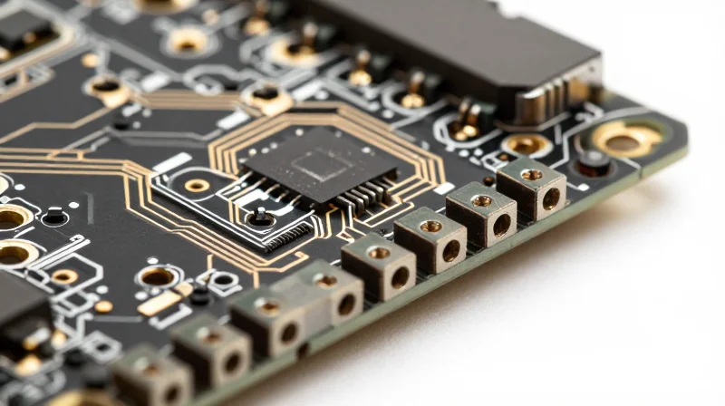
As BMS architectures migrate toward more integrated sensing and control, the PCB landscape has evolved beyond standard multi-layer construction. Modern Battery Management Systems require sophisticated HDI techniques to facilitate high-speed communication and dense component placement within the confined geometry of battery modules. Manufacturers must demonstrate mastery over laser-drilled microvias, sequential lamination processes, and blind/buried via technology to ensure signal integrity and electrical robustness under harsh automotive operating conditions.
Advanced Interconnect Strategies
| Technology | BMS Application | Reliability Benefit |
|---|---|---|
| Laser Microvias | High-density signal routing | Improved mechanical strength and reduced via stress |
| Sequential Lamination | Complex stack-up designs | Increased layer count without excessive board thickness |
| Via-in-Pad | Fine-pitch component mounting | Reduced parasitic inductance for sensitive sensing circuits |
Quality Control in HDI Fabrication
HDI manufacturing introduces unique variables, specifically concerning registration accuracy and plating quality. In high-reliability BMS applications, inconsistencies in copper plating within a microvia can lead to catastrophic open circuits under the thermal cycling stresses inherent in EV environments. When selecting a partner, prioritize those who employ X-ray inspection for cross-section analysis and automated optical inspection (AOI) capable of detecting sub-millimeter defects in HDI layers.
Technical Capability FAQ
- Why are microvias preferred over mechanical drills in BMS designs?
Mechanical drills are limited by aspect ratios; microvias enable much smaller diameters, allowing for denser routing and the integration of advanced ICs required for precise cell balancing. - How does HDI impact thermal management?
HDI allows for the strategic placement of thermal vias directly beneath power MOSFETs and sensing chips, facilitating faster heat dissipation into the ground planes and heat sinks. - What is the primary risk of using low-tier HDI fabrication?
Inadequate plating in high-aspect-ratio vias can result in barrel cracking during the rapid thermal expansion cycles common in automotive battery compartments.
Quality Assurance and Reliability Testing Protocols
The Pillars of Automotive PCB Verification
Reliability in EV-grade BMS hardware requires a layered inspection strategy that transitions from non-destructive optical monitoring to destructive environmental stress screening. Manufacturers must employ a combination of Automated Optical Inspection (AOI), X-ray imaging, and thermal cycling to validate the integrity of solder joints, internal structures, and high-current pathways.
| Testing Method | Primary Application | Defect Identification |
|---|---|---|
| AOI | Surface Component Placement | Solder bridges, polarity, missing components |
| X-Ray (AXI) | BGA/QFN Hidden Joints | Voiding, short circuits, internal alignment |
| Burn-in Testing | Operational Longevity | Infant mortality, latent thermal failures |
Advanced Inspection Technologies
AOI provides high-speed, repeatable surface inspection, yet it is insufficient for complex BMS designs involving high-density interconnects (HDI). Automated X-ray Inspection (AXI) is essential for validating the underside of BGA components and hidden vias where traditional optical systems fail. Manufacturers must ensure their inspection routines are programmable and integrated directly into the production line to maintain real-time traceability.
Reliability and Stress Protocols
Burn-in testing and thermal shock testing simulate the harshest automotive environments. By exposing BMS boards to accelerated temperature cycles while under electrical load, manufacturers can trigger 'infant mortality' failures before the hardware ever reaches the vehicle, ensuring that field reliability aligns with design life expectations.
- Why is X-ray mandatory for BMS boards?
Modern BMS hardware utilizes BGA and QFN packages; X-ray is the only non-destructive method to detect voiding in solder balls and interconnect integrity within dense layers. - How does burn-in testing improve BMS safety?
It weeds out latent component defects that only manifest under specific thermal or power stressors, which is vital for preventing mid-operation battery management failures. - What documentation should I request during an audit?
Always demand access to the 'First Article Inspection' (FAI) reports, AOI fault logs, and documented calibration schedules for all test equipment.
Evaluating Communication and Engineering Support
The Necessity of Early-Phase DFM Integration
Communication with your PCB manufacturer should never be relegated to final file submission. Integrating Design for Manufacturing (DFM) reviews during the initial layout phase is the single most effective way to eliminate re-spins and yield-killing issues. A partner who provides proactive engineering feedback on stack-up impedance, copper weight, and trace-to-pad ratios significantly reduces the risk of structural failure in the field.
Engineering Support Benchmarks
| Feature | Reactive Manufacturer | Proactive Partner |
|---|---|---|
| DFM Feedback | Only after order placement | During schematic/layout review |
| Technical Queries | Delayed email response | Dedicated FAE support |
| Risk Mitigation | Wait for board failure | Simulated thermal/electrical analysis |
Assessing Collaborative Workflow
- How do you evaluate if a manufacturer provides true engineering partnership?
Look for manufacturers who offer dedicated Field Application Engineers (FAEs) assigned specifically to your project, rather than generic customer support portals. - Why is transparency in the DFM reporting process vital?
A high-reliability manufacturer provides detailed, annotated DFM reports that explain 'why' a modification is suggested, enabling your internal team to improve future design choices. - What communication lag is acceptable for EV BMS projects?
In automotive timelines, critical technical queries should receive engineering responses within 24 hours to prevent development bottlenecks.
Ultimately, your PCB partner must operate as an extension of your own engineering team. Choosing a manufacturer that prioritizes transparent, iterative communication during the DFM phase transforms the supplier relationship from a mere commodity purchase to a strategic advantage in the demanding EV battery market.
Selecting an EV PCB manufacturing partner is about more than just cost; it is about building a foundation of reliability for your vehicle's most sensitive components. By prioritizing ISO 26262 compliance, robust material engineering, and transparent production cycles, you protect your brand and your end-users. Ready to optimize your automotive supply chain? Contact our engineering team today for a comprehensive audit of your PCB design and manufacturing requirements.
