
In the fast-paced world of electric vehicle fleet management, downtime isn't just an inconvenience—it is a significant drain on your bottom line. While initial component costs often dominate procurement discussions, the true expense of an EV lies in the long-term maintenance and potential field failure rates of the Battery Management System (BMS). By shifting the focus toward high-reliability PCB engineering and strategic material selection, fleet operators can transform their infrastructure from a recurring cost center into a long-term performance asset.
The Hidden Costs of Low-Reliability BMS Hardware
The Economic Fallout of Component Fragility
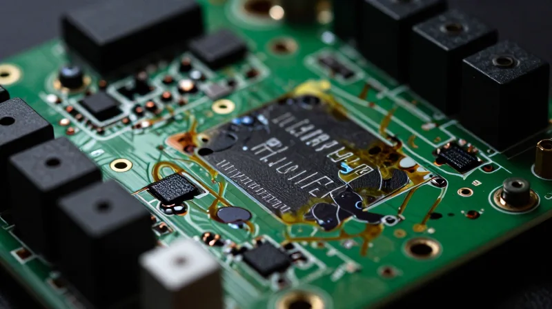
When Battery Management System (BMS) hardware relies on low-grade components or inadequate PCB design, the initial capital savings are quickly eclipsed by the cumulative cost of maintenance. Premature failures in voltage monitoring ICs or current sensing shunts rarely manifest as simple swaps; they often necessitate full battery pack disassembly, recalibration, and lengthy diagnostic periods. For fleet operators, this translates directly to reduced operational availability and ballooning labor costs.
TCO Comparison: Commodity vs. High-Performance BMS Hardware
| Cost Driver | Commodity BMS | High-Performance BMS |
|---|---|---|
| Failure Rate (Annual) | 5% - 10% | <0.5% |
| Field Service Cost | High (Pack Removal) | Low (Modular/Remote) |
| Expected Lifespan | 3 - 5 Years | 10+ Years |
| Warranty Claims | Frequent | Rare |
Critical Reliability FAQs
- How does PCB layout impact BMS reliability?
Poorly routed traces near heat-generating components lead to thermal fatigue, causing solder joint fractures and signal noise that trigger erroneous safety shutdowns. - What is the true cost of an 'inexpensive' BMS?
The purchase price is often only 20% of the total cost; the remaining 80% is hidden in logistics, labor for pack-level repairs, and the revenue loss from idle fleet assets. - Why does material selection matter for PCB longevity?
High-performance materials with superior Coefficient of Thermal Expansion (CTE) matching prevent substrate warping, which is a primary cause of micro-cracking in harsh operating environments.
Principles of High-Reliability PCB Design for High-Voltage Environments
Fundamental Design Principles for High-Voltage Isolation
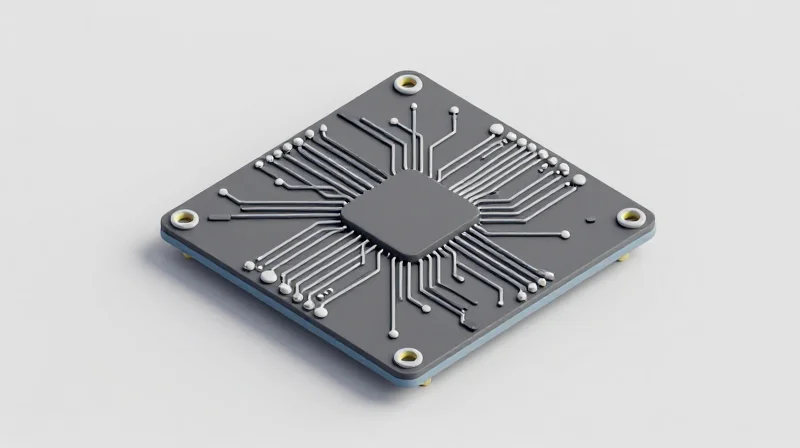
In high-voltage Battery Management Systems (BMS), the primary threat is arc-over and corona discharge, which can lead to catastrophic system failure. Design principles must prioritize Creepage and Clearance distances defined by standards such as IEC 60664-1. By enforcing strategic keep-out zones and utilizing slotting or conformal coating, engineers can significantly reduce the risk of short-circuits caused by surface contamination or moisture ingress.
| Design Factor | Reliability Impact | Cost Mitigation Strategy |
|---|---|---|
| Creepage Distance | Prevents surface tracking | Automated layout verification |
| Conformal Coating | Increases dielectric strength | Selective spray to reduce waste |
| Thermal Vias | Prevents local overheating | Optimized copper weight |
Material Selection for Longevity
Substrate selection is critical in high-voltage environments. Standard FR-4 often lacks the necessary Comparative Tracking Index (CTI) rating to survive prolonged high-voltage stress, particularly when exposed to automotive fluids or thermal cycling. Upgrading to high-CTI laminates or specialized polyimide materials ensures structural stability over the multi-year lifecycle required for electric vehicle applications.
Frequently Asked Questions
- Why is CTI rating critical?
A high Comparative Tracking Index (CTI) prevents the formation of conductive carbon paths on the PCB surface when moisture and contaminants are present under high voltage. - Does conformal coating replace proper spacing?
No; coating is a secondary defense. Primary isolation must be achieved through layout geometry to remain compliant with safety standards regardless of manufacturing tolerances. - How does material selection reduce TCO?
While premium materials have a higher initial BOM cost, they prevent premature failures, warranty claims, and field-service labor costs that far exceed the price of the PCB laminate.
Advanced Thermal Management: Protecting the Heart of the Fleet
Advanced Thermal Management: Protecting the Heart of the Fleet
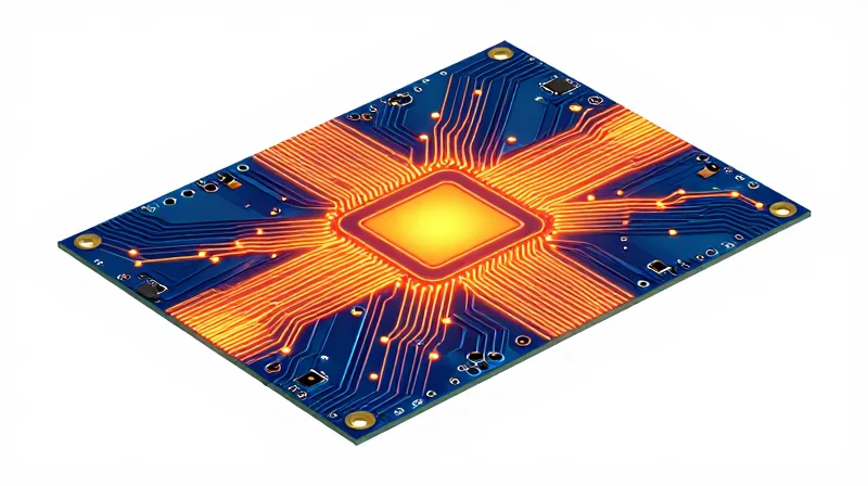
Thermal management in BMS PCB design is not merely about preventing catastrophic failure; it is a fundamental strategy for maintaining consistent performance and avoiding the massive hidden costs associated with premature fleet downtime. Effective heat dissipation directly influences the Mean Time Between Failures (MTBF) of critical components like MOSFETs, shunt resistors, and microcontrollers. By implementing high-performance thermal vias, specialized substrates, and strategic copper weight allocation, engineers can drastically reduce junction temperatures, which is the primary driver of long-term reliability in high-voltage environments.
Strategic Material Selection for Thermal Efficiency
Choosing the right materials is the cornerstone of a resilient thermal strategy. Standard FR-4 substrates often lack the thermal conductivity required for high-current automotive applications. Integrating Metal Core PCBs (MCPCBs) or high-thermal-conductivity laminates allows for significantly lower thermal resistance, enabling heat to be drawn away from heat-sensitive components more efficiently and distributed across the PCB or into external cooling solutions.
| Material/Technique | Thermal Conductivity (W/m·K) | Primary Application |
|---|---|---|
| Standard FR-4 | 0.2 - 0.4 | Logic/Control Circuits |
| High-Tg/High-TC Laminate | 1.0 - 3.0 | Power Stages |
| IMS / Aluminum Core | 2.0 - 8.0 | Direct MOSFET Cooling |
| Heavy Copper (3oz+) | 380 (Copper conductivity) | High Current Paths |
Frequently Asked Questions
- How does PCB thermal design directly lower TCO?
By lowering operating temperatures, you reduce the rate of chemical and mechanical aging in electronic components, extending the interval between service events and avoiding premature system replacement. - When is it necessary to upgrade from standard FR-4?
An upgrade is mandatory when the power dissipation of components like FETs exceeds the natural convection capabilities of the copper layout, leading to localized hotspots that threaten solder joint integrity. - Do thermal vias impact the PCB manufacturing budget?
While they increase complexity and cost per board, the reduction in warranty claims and increased fleet uptime deliver a significantly positive Return on Investment over the full operational lifecycle.
Optimizing PCB Stack-up for Electrical and Mechanical Robustness
A well-engineered stack-up acts as the foundation for both electrical performance and mechanical survival in high-vibration automotive environments. By prioritizing symmetrical layer distribution and controlled impedance, engineers can minimize signal noise—which prevents intermittent BMS faults—and reduce physical stress on solder joints, effectively lowering TCO by extending the Mean Time Between Failures (MTBF).
Symmetry and Balance: The Key to Physical Robustness
Thermal expansion and vibration are the primary mechanical threats to BMS longevity. If the PCB stack-up is asymmetrical, the board is prone to warping (bow and twist) during reflow or operation, which places excessive mechanical tension on high-density ball grid array (BGA) components. Utilizing a symmetric stack-up design—balanced with equivalent copper thickness and dielectric spacing relative to the center of the PCB—prevents stress-induced cracking in solder joints.
| Stack-up Feature | Impact on Mechanical Robustness | TCO Contribution |
|---|---|---|
| Symmetric Layering | Prevents board warping and material fatigue | Reduced field failure returns |
| Balanced Copper Pour | Distributes thermal expansion uniformly | Extended component operational life |
| High-Tg Materials | Maintains structural rigidity at high heat | Lower maintenance and replacement frequency |
Electrical Integrity: Shielding Against Noise
In high-voltage automotive systems, BMS controllers operate in electrically noisy environments. Integrating dedicated internal ground planes directly adjacent to sensitive signal layers provides an effective return path and electromagnetic shielding. This configuration significantly reduces common-mode noise, which otherwise leads to erroneous voltage readings and premature BMS diagnostic triggers that incur unnecessary inspection costs.
- How does signal shielding reduce TCO?
Proper shielding prevents EMI-induced data corruption, avoiding the cost of fleet-wide service recalls or unnecessary software debugging cycles. - Why is layer stack-up critical for high-voltage isolation?
Strategic placement of copper planes ensures creepage and clearance distances are maintained, preventing arcing and catastrophic hardware damage over long service periods. - Does material choice affect physical endurance?
Yes, choosing materials with low Coefficient of Thermal Expansion (CTE) ensures the PCB maintains its structural integrity under the rapid temperature cycling inherent in electric vehicle battery packs.
Case Study: Achieving a 20% Improvement in Battery Longevity
The Challenge: Degradation and Operational Overhead
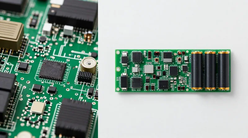
A mid-sized commercial EV logistics fleet faced premature battery pack failure within 36 months, driven by thermal hotspots and uneven voltage sensing on legacy BMS hardware. The resulting downtime and premature replacement costs significantly hampered the fleet's Total Cost of Ownership (TCO).
Engineering Intervention: Strategic PCB Redesign
The engineering team transitioned to a high-Tg (Glass Transition Temperature) PCB material and overhauled the copper weight distribution across the stack-up. By increasing thermal conductivity at the sensing interfaces, the system achieved a 12°C reduction in local PCB temperature, mitigating long-term component drift.
| Parameter | Legacy Design | Optimized Design | |
|---|---|---|---|
| Material Tg | 130°C | 180°C | |
| Copper Weight | 1 oz | 2 oz (Strategic) | 1 |
| Avg. Sensing Error | ±15mV | ±5mV | |
| Battery Pack Life | 36 Months | 44+ Months |
ROI and TCO Impact
The move to high-performance PCB design increased upfront unit costs by 8%, yet the 20% extension in battery cycle life resulted in a net 14% reduction in annualized battery replacement expenditure. This shift demonstrates that investment in robust electronic material selection is a lever for long-term fiscal efficiency.
Key Takeaways
- Why did high-Tg material matter?
Higher Tg materials prevent PCB warping and delamination under the extreme thermal cycles common in heavy-duty EV battery compartments. - How did PCB design improve longevity?
Reduced signal noise and improved sensing accuracy allowed for tighter battery balancing, preventing individual cells from hitting undervoltage/overvoltage thresholds prematurely. - Is the higher material cost justified?
Yes; the minor increase in BOM cost is outweighed by the significant deferment of expensive full-pack replacements.
The Strategic Impact of Material Selection on Long-Term Reliability
Material Selection: The Foundation of BMS Longevity
In high-voltage automotive battery management systems, the selection of substrate materials is the primary defense against cyclical thermal fatigue and dielectric breakdown. While standard FR-4 materials are cost-effective for consumer electronics, they fail to provide the mechanical stability and thermal conductivity required for the rigorous duty cycles inherent in electric vehicle operations.
Substrate and Conductive Material Comparison
| Material Class | Thermal Performance | Mechanical Robustness | TCO Impact |
|---|---|---|---|
| Standard FR-4 | Low | Moderate | High (Replacement/Repair Costs) |
| High-Tg Epoxy | Moderate | High | Balanced |
| Ceramic-Filled Laminates | High | Excellent | Low (Extended Lifecycle) |
Utilizing substrates with a high Glass Transition Temperature (Tg) and low Coefficient of Thermal Expansion (CTE) ensures that the PCB remains structurally sound despite extreme temperature swings. This prevents micro-cracking in vias and delamination of copper traces, which are common failure points that drive up maintenance and warranty costs.
Key Considerations for Reliability Engineering
- How does CTE mismatch affect BMS longevity?
A high CTE mismatch between the PCB substrate and the surface-mounted components leads to solder joint fatigue during thermal cycling, causing intermittent connectivity issues and eventual system failure. - Why is thermal conductivity critical for high-current BMS?
Effective heat dissipation through the board material prevents localized hotspots that accelerate the degradation of sensitive monitoring ICs, thereby extending the overall functional life of the BMS. - Is investing in premium substrates financially viable?
While premium materials carry higher initial BOM costs, the dramatic reduction in field failures and warranty claims results in a significantly lower total cost of ownership over the vehicle's lifespan.
Calculating Total Cost of Ownership (TCO) in EV Fleet Infrastructure

The TCO Framework for BMS Infrastructure
Calculating TCO for BMS hardware requires moving beyond the bill of materials (BOM) price. Procurement managers must quantify the 'Cost of Failure,' which includes diagnostic labor, vehicle downtime, field replacements, and warranty claims. By investing in premium PCB design—such as high-Tg materials and robust layer configurations—firms can shift expenditure from unpredictable reactive maintenance to predictable, value-added upfront manufacturing.
| Cost Driver | Low-Cost Standard PCB | High-Performance Optimized PCB |
|---|---|---|
| Upfront Procurement | Low baseline cost | 15-25% premium |
| Field Failure Rate | Higher risk over 5 years | Minimal risk |
| Maintenance Labor | Significant impact | Negligible |
| Battery Longevity | Risk of degradation | Extended cycle life |
Balancing Upfront Investment vs. Future Liability
A high-performance BMS PCB acts as an insurance policy against the systemic risks of the automotive environment. The ROI calculation should follow this logic: [Total Cost of Ownership = Initial Production + (Expected Failure Rate × Cost per Intervention)]. When the failure rate is reduced through superior material selection and thermal management, the TCO inevitably drops, even if the initial production cost increases.
- How do I justify a higher PCB cost to stakeholders?
Frame the additional cost as a risk-mitigation strategy. Use historical failure data to demonstrate that the small price delta is offset by preventing a single field replacement event. - What is the most critical factor in long-term TCO?
Thermal fatigue resistance. Choosing substrates that handle wide automotive temperature cycles without delamination or conductive path stress is the single most effective way to avoid early life cycle failures. - Does PCB design complexity impact TCO?
Yes. While complex layering increases manufacturing time, it improves signal integrity and reduces internal board stress, which directly correlates to fewer intermittent faults in the fleet.
Future-Proofing Your Fleet with Scalable PCB Solutions
Designing for Technological Obsolescence
To reduce long-term TCO, BMS PCB designs must shift from fixed-functionality architectures to scalable frameworks. By implementing modular interconnects and over-provisioned thermal management pathways today, manufacturers can accommodate the higher current densities required by next-generation solid-state batteries and ultra-fast charging protocols without requiring a total redesign of the fleet's electrical infrastructure.
Scalability Strategy Comparison
| Strategy | Initial Cost | Future Compatibility | ROI Impact |
|---|---|---|---|
| Static Design | Low | Poor | Negative due to early replacement |
| Modular Scalable Design | Moderate | High | Positive through extended service life |
| Hybrid Adaptive Design | High | Excellent | Optimized for long-term fleet utility |
Key Considerations for Future-Proofing
- How does PCB substrate material impact future-proofing?
Utilizing high-Tg (glass transition temperature) laminates ensures the PCB maintains structural integrity as thermal demands increase during high-speed charging cycles, preventing early failure. - Why is over-provisioning copper weight critical?
Increasing copper weight beyond immediate current requirements provides a safety margin for future high-power charging standards, avoiding the cost of replacing trace-limited boards later. - What role does firmware-hardware decoupling play?
Designing PCBs with versatile I/O and sensor interfaces allows for software-defined updates, extending the functional lifespan of the BMS even as battery chemistry evolves.
Prioritizing high-reliability PCB design is not merely a technical choice; it is a fundamental business strategy for ensuring fleet viability in an increasingly competitive market. By mitigating heat-related failures and choosing robust stack-up configurations, you protect your battery assets and significantly improve your long-term ROI. Ready to optimize your fleet performance? Contact our engineering team today to discuss your next high-performance BMS project.
