Imagine adjusting the volume on your favorite music player, not with a physical knob, but with a digital command. This is the power of a digital potentiometer. These tiny components, when paired with an Arduino, allow us to electronically control resistance in circuits. In this article, we’ll demystify how digital potentiometers work, explore different models, and show you how to integrate them with your Arduino projects, unlocking a world of precise control in electronics, from controlling the brightness of an LED, adjusting the speed of a small DC motor or even adjusting audio volume.
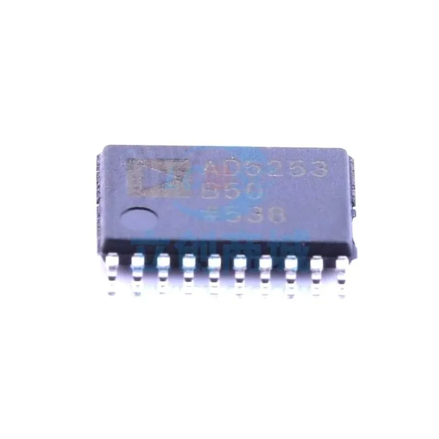
A digital potentiometer, or digipot, is an electronically controlled variable resistor that mimics the function of a traditional analog potentiometer but offers enhanced precision, programmability, and reliability, all controlled through digital signals rather than manual turning. Unlike their analog counterparts, digipots use integrated circuits (ICs) to adjust resistance, enabling seamless integration with microcontrollers like Arduino.
Traditional analog potentiometers rely on a mechanical wiper that moves along a resistive track, causing changes in resistance by mechanical movement. Digital potentiometers, however, utilize an array of resistors and electronic switches to create discrete resistance steps. This structure allows for digitally precise adjustments, making digipots a critical component in modern electronic systems.
| Feature | Analog Potentiometer | Digital Potentiometer |
|---|---|---|
| Adjustment Method | Manual (mechanical) | Electronic (digital signals) |
| Precision | Limited by mechanical accuracy | High, controlled by digital steps |
| Control | Manual and direct | Programmable, microcontroller-compatible |
| Wear | Subject to mechanical wear | No mechanical wear (electronic switching) |
| Remote Control | Not easily implemented | Easily implemented |
| Automation | Not easily automated | Easily automated |
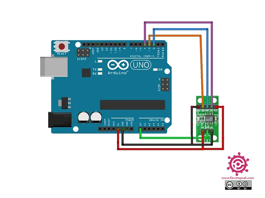
Digital potentiometers offer significant advantages over their analog counterparts, particularly in microcontroller-based applications like those using Arduino. Their ability to be controlled electronically opens up a range of possibilities for automated adjustments, remote control, and precise calibration that are challenging, if not impossible, with traditional analog potentiometers. The integration of digital potentiometers with microcontrollers like Arduino enhances system flexibility and repeatability.
| Feature | Analog Potentiometer | Digital Potentiometer |
|---|---|---|
| Adjustment Method | Manual (mechanical) | Electronic (digital signals) |
| Remote Control | Not easily achievable | Easily achievable via microcontroller |
| Automated Adjustment | Not easily achievable | Easily achievable through programming |
| Precision | Limited by mechanical tolerances | High precision, step-size adjustable |
| Durability | Subject to mechanical wear and tear | High durability, no physical wear |
| Use Cases | Basic circuit adjustments, manual control | Automated systems, remote control, microcontroller-based adjustments |
While digital potentiometers offer compelling advantages, they also have some limitations. They typically require a microcontroller for control, adding to system complexity, and may have specific power requirements. However, the control, repeatability, and durability they afford often justify the added complexity, particularly in modern electronic systems that already incorporate microcontrollers.
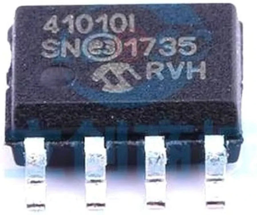
Selecting the appropriate digital potentiometer is crucial for successful Arduino projects. This section details several popular models, outlining their specifications and typical use cases when paired with Arduino microcontrollers. Understanding the nuances of these devices ensures optimal performance and compatibility.
| Model | Type | Resistance Range | Number of Taps | Interface | Typical Arduino Use Cases | Key Features |
|---|---|---|---|---|---|---|
| MCP41100 | Single-Channel | 10 kΩ, 50 kΩ, 100 kΩ | 256 | SPI | General-purpose resistance control, simple adjustments | Cost-effective, easy to implement |
| MCP4231 | Dual-Channel | 10 kΩ, 50 kΩ, 100 kΩ | 256 | SPI | Dual resistance control, audio mixing, dual-channel gain adjustment | Cost effective, two independent pots |
| AD5171 | Single-Channel | 5 kΩ, 10 kΩ, 50 kΩ, 100 kΩ | 64 | I2C | Precise resistance setting, low power applications | Good for low-power projects |
| AD5206 | Six-Channel | 10 kΩ, 50 kΩ, 100 kΩ | 64 | I2C | Multi-channel applications, audio volume control, LED dimming control | Multiple independent pots in a single chip |
| X9C103S | Single-Channel | 10 kΩ | 100 | Up/Down Interface | Basic resistance control, non volatile memory | Simple, non-volatile memory for resistance |
| AD8403 | Quad-Channel | 5 kΩ, 10 kΩ, 50 kΩ, 100 kΩ | 256 | SPI | Multiple resistance control, multi channel gain control | High resolution, four independent pots |
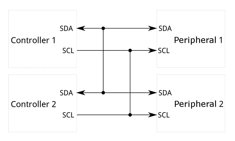
Digital potentiometers often rely on serial communication protocols to receive commands from microcontrollers like the Arduino. The two most prevalent protocols are I2C (Inter-Integrated Circuit) and SPI (Serial Peripheral Interface), each offering unique advantages and implementation specifics that dictate their selection for particular applications.
Understanding the nuances of I2C and SPI is critical for successfully interfacing digital potentiometers with an Arduino, allowing for precise resistance adjustments.
| Feature | I2C (Inter-Integrated Circuit) | SPI (Serial Peripheral Interface) |
|---|---|---|
| Number of Wires | 2 (SDA, SCL) + GND | 3 or 4 (MOSI, MISO, SCK, SS/CS) + GND |
| Addressing | Uses 7-bit or 10-bit addressing, allowing multiple devices on the same bus | Uses Slave Select (SS) or Chip Select (CS) pin, typically one-to-one communication |
| Speed | Relatively slower, typically up to 400kHz (standard mode) or 1MHz (fast mode) | Faster than I2C, can reach several MHz |
| Complexity | More complex protocol handling due to addressing and data packet management | Simpler protocol, easier to implement in hardware and software |
| Suitable Applications | Ideal for applications with multiple devices or where wiring needs to be minimized | Suitable for high-speed data transfer, often used in displays, sensors, and memory |
Interfacing with Arduino requires precise wiring. For I2C, you'll typically connect the potentiometer's SDA pin to Arduino's SDA (usually pin A4 on older boards, pin 20 on Mega) and SCL to SCL (usually pin A5, pin 21 on Mega) alongside power and ground. For SPI, MOSI, MISO and SCK pins of the potentiometer connect to Arduino pins 11, 12, and 13 respectively and a dedicated GPIO pin acts as the SS/CS pin, in addition to power and ground. Ensure to use the correct communication protocol specified by your potentiometer's datasheet.
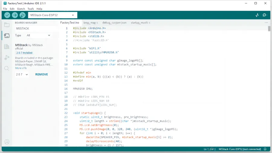
Controlling a digital potentiometer with an Arduino involves sending specific commands via communication protocols like SPI or I2C. This section provides a practical, step-by-step guide with example code snippets to get you started. The focus is on the essential operations: initializing the communication, setting the desired resistance, and, where applicable, reading current settings.
Before diving into the code, it's essential to understand the fundamental steps involved, which are generally consistent across different digital potentiometer models. These steps encompass establishing communication using specific pins, sending control bytes to adjust the wiper position, and implementing appropriate delay for device stabilization. The following examples will demonstrate these aspects, typically using either SPI or I2C protocol.
For SPI protocol, it's important to initialize the SPI bus with the correct settings using the SPI.begin() command. The chip select pin must also be managed correctly, brought low before communication starts, and high after. For I2C protocol, the Wire library is utilized, typically with commands like Wire.begin() to start communication and Wire.write() to transmit data. The code examples provided below are structured with these key steps and best practices to ensure efficient and accurate control of your digital potentiometer.
// Example using SPI protocol for an MCP41100 digital potentiometer

#include

const int CS_PIN = 10; // Chip Select Pin for SPI

void setup() {
  Serial.begin(9600);
  SPI.begin();
  pinMode(CS_PIN, OUTPUT);
  digitalWrite(CS_PIN, HIGH); // Initialize CS pin high
}

void setResistance(int value) { // value range 0 - 255
  digitalWrite(CS_PIN, LOW);
  SPI.transfer(0x00); // Command byte to set wiper position
  SPI.transfer(value); // Value for wiper position (0-255)
  digitalWrite(CS_PIN, HIGH);
  delay(10); // Small delay for the device to settle
}

void loop() {
  for (int i = 0; i <= 255; i += 5) {
   setResistance(i); // Increment resistance
   Serial.print("Resistance: ");
   Serial.println(i);
   delay(100);
  }
   for (int i = 255; i >= 0; i -= 5) {
   setResistance(i); // Decrement resistance
    Serial.print("Resistance: ");
    Serial.println(i);
    delay(100);
  }
}
// Example using I2C protocol for an AD5206 digital potentiometer
#include
const int AD5206_ADDRESS = 0x2E; // I2C address of AD5206
void setup() {
Serial.begin(9600);
Wire.begin();
}
void setResistance(int channel, int value) { // channel 0 - 5, value 0-255
if (channel < 0 || channel > 5) return; // Check for valid channel
Wire.beginTransmission(AD5206_ADDRESS);
Wire.write(channel); // Select the channel
Wire.write(value); // Set wiper position
Wire.endTransmission();
delay(10);
}
void loop() {
for (int i = 0; i <= 255; i += 5) {
for (int channel = 0; channel < 6; channel++){ // Set resistance for all 6 channels
setResistance(channel,i);
}
Serial.print("Resistance: ");
Serial.println(i);
delay(100);
}
for (int i = 255; i >= 0; i -= 5) {
for (int channel = 0; channel < 6; channel++){ // Set resistance for all 6 channels
setResistance(channel,i);
}
Serial.print("Resistance: ");
Serial.println(i);
delay(100);
}
} 
Digital potentiometers, when combined with the control capabilities of an Arduino, unlock a multitude of applications requiring precise and adjustable resistance. Unlike their mechanical counterparts, digital potentiometers offer repeatable and electronically adjustable resistance values, facilitating dynamic control in various electronic circuits. This section will demonstrate how this versatile component can be implemented in various Arduino projects.
| Application | Description | Arduino Implementation | Benefits |
|---|---|---|---|
| LED Brightness Control | Dynamically adjust the brightness of an LED | Digital Potentiometer in series with LED, control resistance via Arduino commands | Precise control, dimming effects, automated adjustments |
| Motor Speed Regulation | Control the speed of a DC motor. | Digital Potentiometer adjusts the voltage supply to a motor driver. | Fine-tuned speed control, ideal for robotics applications |
| Audio Volume Adjustment | Adjust the audio signal amplitude. | Digital Potentiometer acts as a variable gain within an audio circuit. | Digitally controllable volume, applicable to audio processing |
| Programmable Gain Amplifiers | Adjust the gain of an input signal. | Digital Potentiometer in the feedback loop of an op-amp | Variable signal amplification, suitable for sensor signal conditioning |
Successfully integrating digital potentiometers with Arduino can sometimes present challenges. This section addresses typical issues encountered, such as communication failures, unexpected resistance readings, and wiring errors, providing actionable solutions to ensure smooth operation.
This section addresses common questions and concerns regarding the use of digital potentiometers with Arduino, providing clarity on programming, selection, and integration.
Beyond basic resistance adjustments, digital potentiometers interfaced with Arduino can achieve sophisticated control through techniques like Proportional-Integral-Derivative (PID) control, data smoothing, and custom functions, enabling more precise and tailored system behavior.
These techniques elevate the functionality of digital potentiometers in Arduino projects, moving from simple variable resistors to components of dynamic control systems.
| Technique | Description | Advantages | Use Case |
|---|---|---|---|
| PID Control | Utilizes feedback to continuously adjust resistance. | Precise control, stability | Temperature control, motor speed regulation |
| Data Smoothing | Reduces step changes for smoother transitions. | Avoids abrupt changes and instability | Audio volume adjustment, LED dimming |
| Custom Functions | Tailored control for unique requirements | Flexible adjustment profiles | Non-linear gain control, application specific adjustment |
The digital potentiometer provides a convenient way to introduce electronically controlled resistance into your Arduino projects, opening up a vast array of applications. From precisely adjusting parameters in electronic circuits to automating control systems, the capabilities of digital potentiometers expand the possibilities of what's achievable with Arduino. By exploring different models, programming techniques, and practical implementations, you can leverage this versatile component to create more sophisticated, adaptable, and user-friendly electronic projects.

