The humble 22uF capacitor, a seemingly small component, plays a critical role in countless electronic circuits, from smoothing power supplies to timing circuits. Like a tiny rechargeable battery, it stores energy and can release it quickly, contributing to the stability and performance of devices we use daily, and is frequently encountered in many electronic devices, from televisions to audio equipment. This article will demystify the 22uF capacitor, exploring its different types, key characteristics, applications, and how to select the appropriate component for your next project, starting with a look at its basic function in the world of electronics.
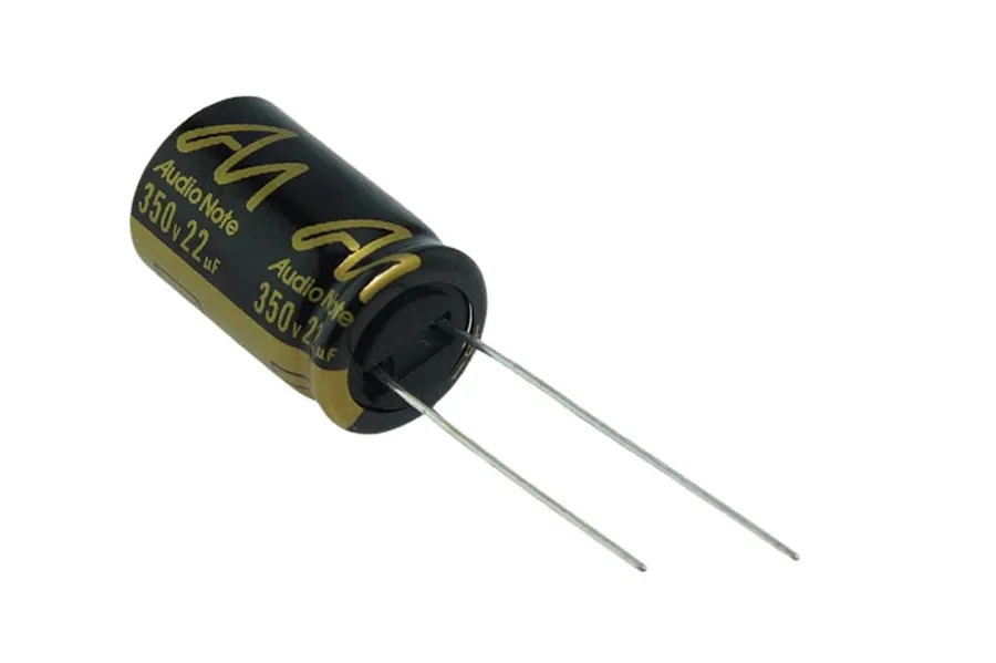
A 22uF capacitor is a fundamental passive electronic component characterized by its ability to store electrical energy, with a specific capacitance of 22 microfarads (µF). This component plays a crucial role in various electronic circuits, serving functions such as filtering, energy storage, and managing electrical flow.
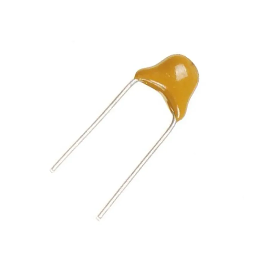
22uF capacitors are fundamental components in electronics, available in several types to suit diverse application needs. The primary types are ceramic, electrolytic, and tantalum, each exhibiting distinct characteristics in terms of performance, physical size, and cost, necessitating careful consideration of specific application requirements when selecting a 22uF capacitor.
| Capacitor Type | Polarity | Size | Typical Applications | Pros | Cons |
|---|---|---|---|---|---|
| Ceramic | Non-Polarized | Small | High-frequency circuits, bypass capacitors | Stable, low cost, good high frequency performance | Lower capacitance values, susceptible to DC bias effects |
| Electrolytic (Aluminum) | Polarized | Larger | Power supply filtering, signal coupling | High capacitance, good for filtering | Polarized, higher ESR, limited high frequency performance |
| Tantalum | Polarized | Medium | Power supply filtering, decoupling | Stable, good frequency response | Polarized, more expensive, can fail catastrophically |
| Surface Mount Device (SMD) | Varies | Very Small | High-density PCBs, automated assembly | Compact, ideal for SMT assembly | Can be difficult to manually handle |
Ceramic capacitors are characterized by their non-polarized nature and small physical size, offering exceptional stability and high-frequency performance. These capacitors are commonly employed in high-frequency applications and are frequently used in bypass and decoupling circuits, owing to their ability to operate efficiently at high frequencies with minimal losses. Their construction involves ceramic dielectric materials, which enable their stable performance across a range of temperatures and frequencies.
Electrolytic capacitors, most commonly constructed with aluminum, are polarized components offering high capacitance values in compact volumes. They are typically available in axial and radial lead configurations and are predominantly used in power supplies for filtering applications. Their polarized nature necessitates careful consideration of circuit polarity during installation to prevent component damage. The large capacitance of electrolytic capacitors makes them suitable for applications requiring high energy storage or significant filtering capabilities.
Surface Mount Device (SMD) capacitors are specifically designed for automated assembly processes and are characterized by their highly compact form factor. Ideal for use in PCB assemblies where space is limited, SMD capacitors are easily soldered to the surface of the printed circuit board. These capacitors are available in various types, such as ceramic and tantalum, to accommodate different application needs. Their small size and compatibility with automated processes make them essential in modern electronics manufacturing.
Ceramic capacitors, characterized by their non-polarized nature and compact size, are widely utilized in electronic circuits for their stability, particularly in high-frequency operations. Their construction employs a ceramic dielectric material, allowing for reliable performance across a range of temperatures and frequencies.
| Property | Description | Typical Values for 22uF Ceramic Capacitor |
|---|---|---|
| Polarity | Indicates the direction of current flow | Non-Polarized |
| Size | Physical dimensions of the capacitor | Very small, typically SMD packages like 0805 or 1206 |
| Temperature Coefficient | How much capacitance changes with temperature | Varies with dielectric material, typically stable |
| ESR | Equivalent series resistance, impacts performance in power applications | Typically very low, beneficial for high-frequency applications |
| Voltage Rating | Maximum safe voltage the capacitor can withstand | Varies with type, 6.3V to 100V or higher |
| Tolerance | The acceptable variation in capacitance from the nominal value | Ranges from 5% to 20% |
Electrolytic capacitors are characterized by their polarized nature, meaning they have a defined positive and negative terminal, and they offer a high capacitance-to-volume ratio. Typically constructed using aluminum, these capacitors are available in axial and radial lead configurations, making them suitable for various mounting options. Their high capacitance makes them particularly well-suited for filtering applications in power supplies, where they effectively smooth out voltage fluctuations.
| Feature | Description |
|---|---|
| Polarity | Polarized (has positive and negative terminals) |
| Capacitance Density | High capacitance per unit volume |
| Typical Material | Aluminum |
| Lead Configuration | Available in Axial and Radial lead types |
| Primary Application | Filtering in power supplies, smoothing voltage ripples |
| Advantages | High capacitance, Relatively low cost |
| Disadvantages | Polarized, higher ESR than ceramic capacitors, limited life expectancy |
Surface Mount Device (SMD) capacitors, including the 22uF variant, are designed for automated assembly and are characterized by their compact size, making them ideal for printed circuit boards (PCBs) where space is a premium. These components are directly mounted onto the surface of the PCB, eliminating the need for through-hole leads.
| Feature | SMD Capacitor (22uF) | Leaded Capacitor (22uF) |
|---|---|---|
| Mounting | Surface Mount | Through-Hole |
| Size | Very Compact | Larger |
| Assembly | Automated | Manual or Automated |
| Application | Space-Constrained PCB | General Purpose |
| Profile | Low Profile | Higher Profile |
Selecting the correct 22uF capacitor requires understanding several key specifications beyond its capacitance value. These parameters directly impact the capacitor's performance and suitability for a given application. This section delves into the critical specifications to consider.
| Specification | Description | Importance |
|---|---|---|
| Capacitance | The nominal value is 22 microfarads (uF). | Determines the amount of charge the capacitor can store. Essential for circuit timing, filtering, and energy storage. |
| Voltage Rating | Maximum voltage the capacitor can withstand without damage. | Crucial for preventing capacitor failure. Must exceed the maximum voltage in the circuit. |
| Tolerance | The allowable deviation from the nominal capacitance, typically expressed as a percentage. | Affects precision in timing or sensitive filtering applications. Lower tolerance capacitors offer greater accuracy. |
| Equivalent Series Resistance (ESR) | The internal resistance of the capacitor at a given frequency. | Critical for filtering and power applications. Low ESR results in less heat generation and better efficiency. |
| Temperature Coefficient | How the capacitance changes with temperature. | Affects stability in high or low temperature environments. A lower temperature coefficient is preferred in precision circuits. |
| Leakage Current | The small current that flows through the capacitor even when it's charged. | Important when the capacitor is required to hold a charge for a long period. Lower leakage is better for holding charge. |
| Dielectric Type | The material between the capacitor's plates. | Different dielectrics affect the capacitance value, temperature stability, and frequency response. Choose based on specific application requirements (e.g., ceramic, tantalum, electrolytic). |
| Physical Size and Package | The physical dimensions and the form factor of the capacitor. | Critical for the physical design of the circuit board. Considerations include size constraints, mounting options (SMD vs. leaded), and board space. |
The voltage rating of a capacitor specifies the maximum DC voltage it can safely withstand without dielectric breakdown. Selecting a capacitor with an inadequate voltage rating can lead to component failure, often resulting in damage or permanent degradation of performance. It's a cardinal rule to select a capacitor with a voltage rating at least 20% greater than the maximum expected voltage in the circuit to ensure reliable operation and safety.
Capacitor tolerance indicates how much the actual capacitance value of a component may vary from its stated nominal value, typically 22uF in this case. Tolerance is usually expressed as a percentage and can range from as tight as ±1% for precision applications to ±20% or even more for less critical uses. This deviation can affect circuit performance, particularly in applications that require accurate timing, or filtering.
Equivalent Series Resistance (ESR) is the intrinsic resistance within a capacitor, particularly significant at higher frequencies. A low ESR is crucial in applications where capacitors are used for filtering or decoupling to minimize losses, reduce heat generation, and improve efficiency. High ESR can result in performance degradation and premature failure, particularly in high-current applications such as switching power supplies. Therefore, when choosing a 22uF capacitor for filtering or power applications, opting for a capacitor with low ESR is important for optimal performance and longevity.
The voltage rating of a capacitor, particularly a 22uF capacitor, is a critical specification that indicates the maximum DC voltage the component can safely withstand without risk of failure or damage. Exceeding this voltage rating can lead to dielectric breakdown, causing the capacitor to short circuit, overheat, and potentially damage other components in the circuit. Therefore, selecting a capacitor with an adequate voltage rating is paramount for the reliability and safety of any electronic design.
The voltage rating of a capacitor is not a measure of performance, but rather a safety threshold. It is defined by the capacitor's construction and the properties of its dielectric material, which is the insulating layer between the capacitor's conductive plates. The dielectric material has a maximum electric field strength it can withstand before it becomes conductive, leading to a breakdown.
To ensure reliable operation, a general guideline is to choose a 22uF capacitor with a voltage rating that is significantly higher than the highest expected voltage in the circuit. A common practice is to use a safety margin of 20% to 50%, although specific application requirements may call for greater safety headroom. For instance, if the circuit operates at 12V, selecting a capacitor rated for 16V or higher is advisable.
| Application Scenario | Circuit Voltage | Recommended Voltage Rating (22uF Capacitor) |
|---|---|---|
| Low-power digital logic | 3.3V | 6.3V or 10V |
| Battery-powered device | 5V | 10V or 16V |
| Power supply filtering | 12V | 16V or 25V |
| Automotive applications | 13.8V | 25V or 35V |
| Industrial Power Systems | 24V | 35V or 50V |
Selecting the correct voltage rating is also essential in avoiding performance degradation of the capacitor over time. Capacitors operated near their maximum voltage rating may experience increased degradation, reduced lifespan and increased risk of failure. Moreover, selecting an appropriately rated capacitor can optimize for both reliability and cost by avoiding oversizing.
Capacitor tolerance specifies the allowable deviation of a capacitor's actual capacitance from its nominal or stated value. For a 22uF capacitor, the tolerance indicates how much the real-world capacitance can vary above or below the 22 microfarad (uF) mark. This deviation is usually expressed as a percentage of the nominal capacitance and significantly impacts the performance of sensitive circuits where precise capacitance values are required.
| Tolerance Range | Implication | Application Considerations |
|---|---|---|
| ± 5% | Very precise capacitance; minimal deviation from the nominal value. | Precision timing circuits, analog filters, and high-accuracy applications. |
| ± 10% | Moderate precision; acceptable for many general-purpose applications. | General signal coupling, bypass capacitors, non-critical timing circuits. |
| ± 20% | Less precise capacitance; substantial deviation is possible. | Power supply filtering, where slight variations are acceptable. |
Equivalent Series Resistance (ESR) in a 22uF capacitor represents the inherent resistance within the capacitor itself, arising from factors like electrode material, electrolyte conductivity, and terminal connections. This resistance affects how efficiently the capacitor charges and discharges, particularly impacting its performance in power applications. Specifically, a lower ESR is crucial for effective filtering and handling higher currents, and directly affects the overall performance of the circuit.
The ESR value is not a static property; it varies with temperature and frequency. Therefore, it is critical to assess the datasheet and specifications of the capacitor based on the operating conditions of the application. For critical application a low ESR capacitor selection is crucial to improve the overall power handling and filtering capabilities, especially in switching power supplies.
| Parameter | Description | Impact |
|---|---|---|
| ESR | Equivalent series resistance of the capacitor. | Higher ESR leads to increased power loss, reduced filtering, and increased heat generation. Lower ESR is preferred for power applications. |
| Measurement unit | Measured in ohms (Ω). | Typical ESR values for 22uF capacitors range from a few milliohms to a few ohms, varying by type and manufacturing process. |
| Frequency dependence | ESR can vary with frequency. | Higher frequencies can lead to increases in ESR. Datasheets usually provide ESR values at specific test frequencies. |
| Temperature dependence | ESR is sensitive to temperature variation. | Higher temperature may increase ESR. Understanding this is important for designs operating in a wide temperature range. |
| Impact on filtering | Lower ESR leads to better filtering performance. | A low ESR capacitor effectively attenuates ripple noise in power supply circuits. |
| Impact on power | Lower ESR allows handling of higher currents efficiently. | High ESR results in greater power loss as heat, which can be detrimental to the circuit and capacitor reliability. |
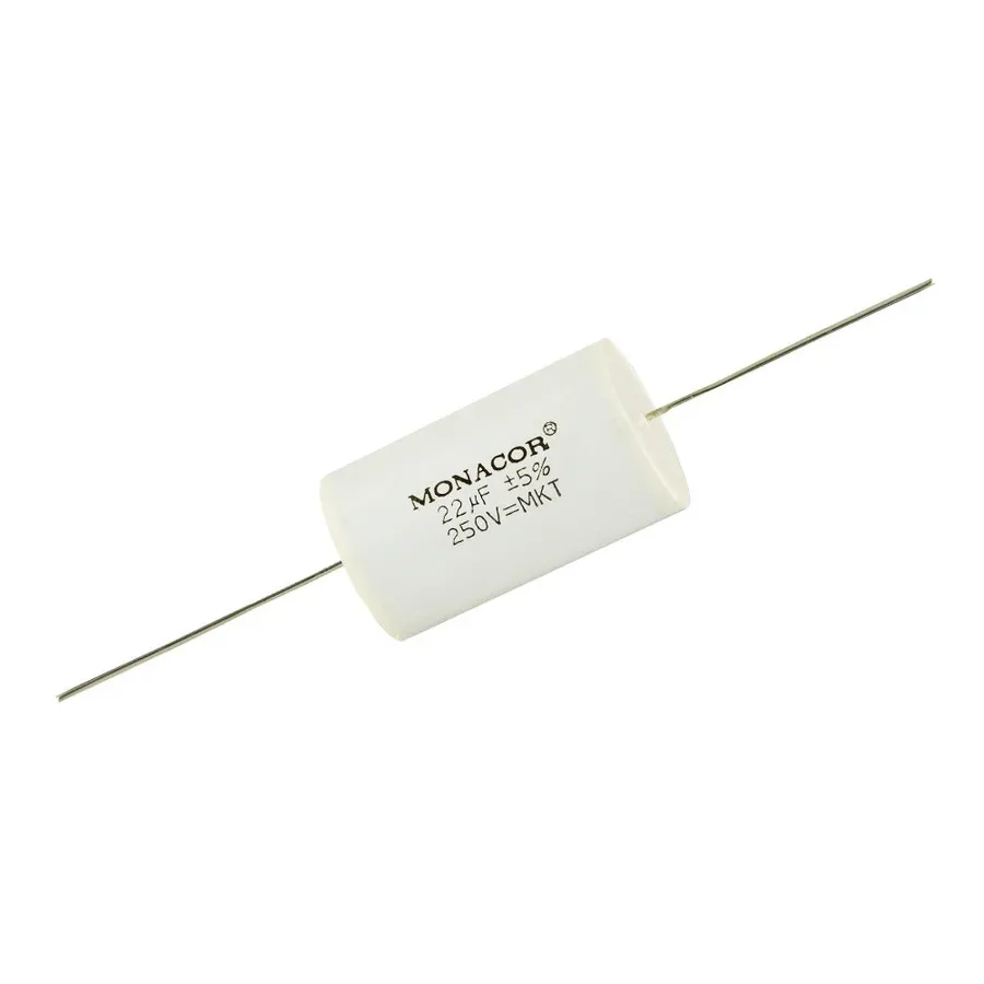
22uF capacitors are versatile components utilized across a broad spectrum of electronic applications, primarily for filtering, coupling, and timing functions. Their specific characteristics make them suitable for a variety of contexts within circuit designs.
| Application | Function | Benefits |
|---|---|---|
| Power Supply Filtering | Smoothing voltage ripple | Stable DC output, reduced noise |
| Signal Coupling | Blocking DC signals, passing AC signals | Enables signal transfer between stages, prevents DC bias issues |
| Timing Circuits | Creating time delays or oscillations | Timing control in circuits, pulse generation |
| Decoupling | Reducing noise and voltage drops on power rails | Reliable operation of ICs |
| Audio Circuits | Filtering and coupling audio signals | Improved audio quality, reduced distortion |
Selecting the appropriate 22uF capacitor is crucial for optimal circuit performance and reliability. The choice is heavily dependent on the specific application requirements, encompassing electrical parameters, environmental conditions, and physical constraints. A careful evaluation of these factors is essential to ensure the capacitor functions as intended within the system.
Consider the application's voltage, physical size, and mounting requirements to make the correct selection.
When choosing a 22uF capacitor, the voltage rating is a critical parameter. It's essential to select a capacitor with a voltage rating that significantly exceeds the maximum voltage expected in your circuit to avoid capacitor failure. For filtering applications, account for the ripple voltage, which adds to the nominal DC voltage. Selecting a capacitor with a safety margin ensures reliable operation and prevents premature degradation. For signal coupling, the dielectric material of the capacitor should be chosen based on the frequency of the signal to minimize signal loss and distortion.
Physical dimensions and mounting methods of a 22uF capacitor are paramount for integration with your circuit board. SMD (Surface Mount Device) capacitors are compact and designed for automated assembly, making them suitable for space-constrained PCBs. Leaded capacitors, available in axial and radial configurations, are better suited for through-hole mounting in prototype boards and in applications where manual soldering is employed. Ensure that the capacitor's footprint and lead configuration are compatible with the PCB layout to facilitate efficient assembly and reliable connections.
| Consideration | SMD Capacitor | Leaded Capacitor |
|---|---|---|
| Assembly | Automated assembly | Manual soldering |
| Size | Compact, ideal for high-density PCB | Larger, good for through-hole PCB |
| Applications | Space-constrained PCB | Prototype and manual assembly PCB |
Selecting the correct voltage rating for a 22uF capacitor is crucial for circuit reliability and performance. The voltage rating indicates the maximum DC voltage the capacitor can safely handle without risk of dielectric breakdown or failure. For filtering applications, especially in power supplies, the presence of ripple voltage requires that the capacitor's voltage rating be significantly higher than the nominal operating voltage. This ensures that the capacitor can withstand voltage fluctuations without degrading or failing. Conversely, for coupling applications, where the primary concern is the transmission of AC signals, the selection should consider the signal's frequency and amplitude to ensure that the dielectric material is suitable and can handle the AC voltage without adverse effects.
| Application Type | Voltage Considerations | Dielectric Considerations |
|---|---|---|
| Power Supply Filtering | Choose a capacitor with a voltage rating significantly higher than the expected DC voltage and ripple voltage. A safety margin of at least 20-30% is recommended. For example, a 12V supply should use a capacitor rated for 16V or higher. | Electrolytic capacitors are typically used due to their high capacitance values, but ESR is also an important factor. |
| Signal Coupling | Select a capacitor with a voltage rating that is appropriate for the signal’s amplitude to avoid distortion or damage. The voltage should be significantly greater than the maximum signal voltage. | Ceramic capacitors are often preferred due to their low equivalent series resistance (ESR) and high frequency response. |
Selecting the correct physical size and mounting type for a 22uF capacitor is crucial for ensuring proper integration into your circuit. The physical dimensions and mounting style directly impact the capacitor's fit on the Printed Circuit Board (PCB) and affect the assembly process. Considerations include the board layout, available space, and manufacturing method.
| Mounting Type | Description | Advantages | Disadvantages | Typical Applications |
|---|---|---|---|---|
| Surface Mount Device (SMD) | Designed for direct mounting onto the surface of a PCB without lead holes. | Compact, ideal for high-density boards, allows for automated assembly. | Requires specialized equipment for placement and soldering, less robust for manual handling. | High-volume consumer electronics, portable devices |
| Through-Hole (Leaded) | Features leads that are inserted into holes on the PCB for soldering. | More robust, easier to handle manually, better for prototyping. | Larger footprint, not suitable for high-density boards, more labor-intensive assembly. | Prototyping, low-volume production, applications with high mechanical stress |
The physical size of a 22uF capacitor, especially electrolytic types, can vary depending on voltage ratings and manufacturer. It's important to consult datasheets for precise measurements and ensure that the capacitor will fit within the allocated space on the PCB.
This section addresses common questions regarding 22uF capacitors, offering clear and concise answers to aid understanding and application.
22uF capacitors are versatile passive components employed across various electronic circuits for several core functions. Primarily, they serve in filtering, decoupling, timing, and signal coupling applications. The specific use of a 22uF capacitor is determined by its electrical properties within a circuit, making it a fundamental element in circuit design.
The symbol 'uF' on a capacitor denotes microfarads, the standard unit for measuring capacitance. A microfarad (uF) is equivalent to one millionth of a farad, a larger unit of capacitance. Understanding this unit is crucial for correctly selecting and utilizing capacitors in electronic circuits.
The physical size of a 22uF capacitor is not fixed; it varies significantly depending on several factors, primarily the capacitor's type, voltage rating, and manufacturing specifics. While the capacitance value (22uF) indicates its ability to store charge, the physical dimensions relate to the construction and materials used.
A 0.22uF capacitor, having a capacitance of 0.22 microfarads, is a component employed in electronic circuits for energy storage and filtering. Its capacitance value is one tenth of a 22uF capacitor and this difference significantly impacts its usage, typically suiting applications that require higher frequency filtering or lower energy storage.
While both 0.22uF and 22uF capacitors perform similar basic functions of storing and releasing electrical energy, their distinct capacitance values make them suitable for different applications.
The 22uF capacitor, with its seemingly simple function, is a workhorse of modern electronics. Understanding its types, specifications, and applications is key to designing reliable and efficient circuits. Whether it's smoothing power supplies or timing circuits, the correct choice and application of a 22uF capacitor can make all the difference. Always consider the voltage, tolerance, and mounting requirements before selecting a 22uF capacitor for your electronic projects.

