Capacitors, like the ubiquitous 103 capacitor, are fundamental components in electronic circuits, acting as tiny energy reservoirs. Understanding their markings and values is crucial for anyone working with electronics. Let’s delve into the world of the 103 capacitor and explore what it does, how it works, and why it is indispensable in modern technology. From smoothing power delivery to precise timing, capacitors like the 103, rated at 10nF, play a silent yet vital role in our electronic devices.
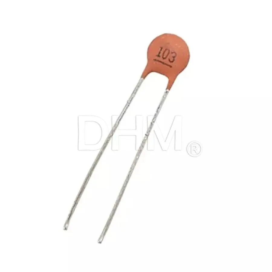
The '103' marking on a capacitor is a standardized code indicating its capacitance value, a fundamental property that determines how much electrical charge it can store. This code, prevalent on ceramic disc capacitors, is not a direct reading in farads (F), but rather a shorthand method based on a numerical system where the first two digits represent the significant figures, and the third digit represents a multiplier.
Specifically, for a '103' coded capacitor, the '10' represents the base value, and '3' indicates a multiplier of 10³, meaning the base value is multiplied by 1000. The unit is in picofarads (pF). Therefore the actual value of a 103 capacitor is 10 * 10³ pF or 10,000 pF.
The '103' code on a capacitor directly translates to its capacitance value, a critical parameter in circuit design. Specifically, a 103 capacitor denotes a capacitance of 10,000 picofarads (pF), which can be expressed in other commonly used units as well.
| Unit | Value |
|---|---|
| Picofarads (pF) | 10,000 pF |
| Nanofarads (nF) | 10 nF |
| Microfarads (µF) | 0.01 µF |
Understanding these conversions is crucial for accurately selecting and utilizing 103 capacitors within electronic circuits. The 103 capacitor, due to its relatively small capacitance, is typically employed in applications where precise timing and high-frequency filtering are required. The conversion of 10,000 pF to 10 nF and then to 0.01 µF demonstrates the relationship between different units of capacitance and shows how a small numerical change can drastically change the order of magnitude of the unit involved.
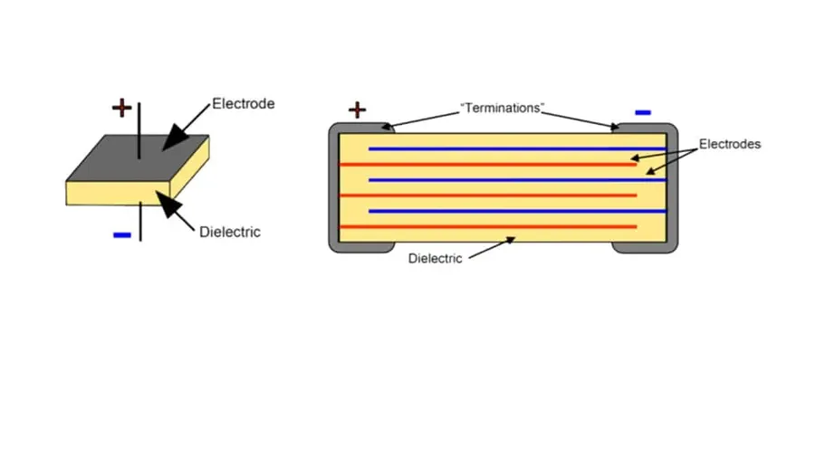
The 103 capacitor is predominantly a ceramic disc capacitor, chosen for its stability, reliability, and consistent performance under specified operating conditions. Its construction and material composition play a critical role in these characteristics. Understanding these aspects is crucial for proper application and performance evaluation.
| Property | Description |
|---|---|
| Dielectric Material | Typically a ceramic compound such as barium titanate or other similar metal oxides. These materials offer high permittivity, contributing to the capacitor's ability to store charge. |
| Electrode Material | The electrodes are typically made from a conductive metal, often silver or a silver alloy, applied to the ceramic dielectric material. These electrodes facilitate the flow of current in and out of the capacitor. |
| Encapsulation | The entire capacitor assembly is often encapsulated in a protective coating, such as epoxy or phenolic resin, to shield the internal components from moisture and physical damage. This improves the capacitor's long-term stability and reliability. |
| Temperature Characteristics | Ceramic capacitors exhibit varying degrees of temperature stability. Common temperature coefficients include NP0 (or C0G) which offers excellent stability over temperature, X7R which is a more general-purpose material, and Y5V which has higher capacitance but is not as stable. The specific type influences its performance in various operating environments. |
| Construction Type | The 'disc' form factor is standard for many ceramic capacitors. They are available in various sizes and lead configurations to suit diverse mounting and connection requirements. Additionally, surface mount versions are available. |
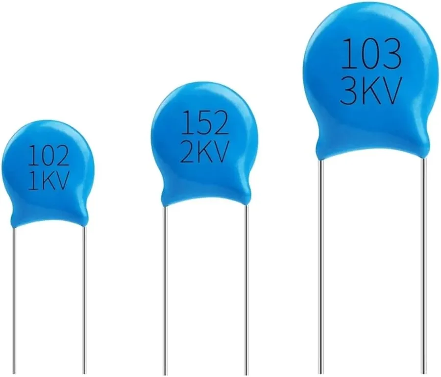
The voltage rating of a 103 capacitor is paramount for ensuring safe and reliable operation within electronic circuits. This rating, often marked on the capacitor's body, indicates the maximum voltage that the capacitor can withstand without risking dielectric breakdown or damage. Exceeding this limit can result in component failure, potentially causing damage to other parts of the circuit or creating safety hazards.
Understanding and adhering to the voltage rating is crucial for preventing catastrophic failures and maintaining circuit integrity. The voltage rating is typically specified with a numeric value followed by a voltage unit symbol (e.g., V for volts or KV for kilovolts). For example, a 100V rating means the capacitor should not be used in applications where the sustained voltage across it exceeds 100 volts. A 1KV rating indicates a maximum sustained voltage of 1000 volts.
It's important to note that the voltage rating is not an operational guideline but a hard limit. Operating the capacitor near its maximum rating can lead to reduced lifespan and increased risk of failure. A common design practice is to select a capacitor with a voltage rating significantly higher than the maximum expected voltage in the circuit to provide a margin of safety and to account for voltage spikes or surges.
| Voltage Rating Marking | Meaning | Safety Consideration |
|---|---|---|
| 100V | Maximum 100 Volts DC | Do not exceed 100V DC in the circuit |
| 1KV | Maximum 1000 Volts DC | Do not exceed 1000V DC in the circuit |
| 50V | Maximum 50 Volts DC | Do not exceed 50V DC in the circuit |
| 250V | Maximum 250 Volts DC | Do not exceed 250V DC in the circuit |
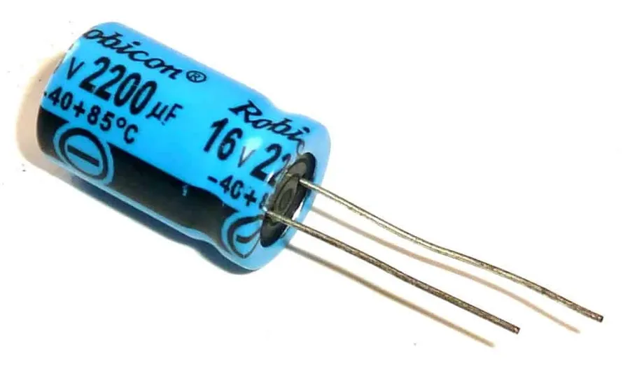
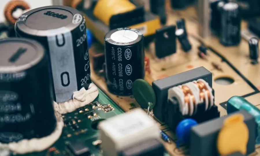
The 103 capacitor, with its capacitance of 10nF or 0.01µF, finds extensive use across various electronic circuits due to its suitable characteristics for decoupling, filtering, and timing applications. Its compact size and relative stability make it a ubiquitous component in modern electronics.
These applications exemplify the versatility of the 103 capacitor in various electronic designs. Its small size, low cost and availability make it a practical choice for both simple and complex circuits. When selecting a 103 capacitor for a specific application, it’s crucial to consider not only the capacitance but also other factors like voltage rating, temperature coefficient, and tolerance to ensure reliable operation.
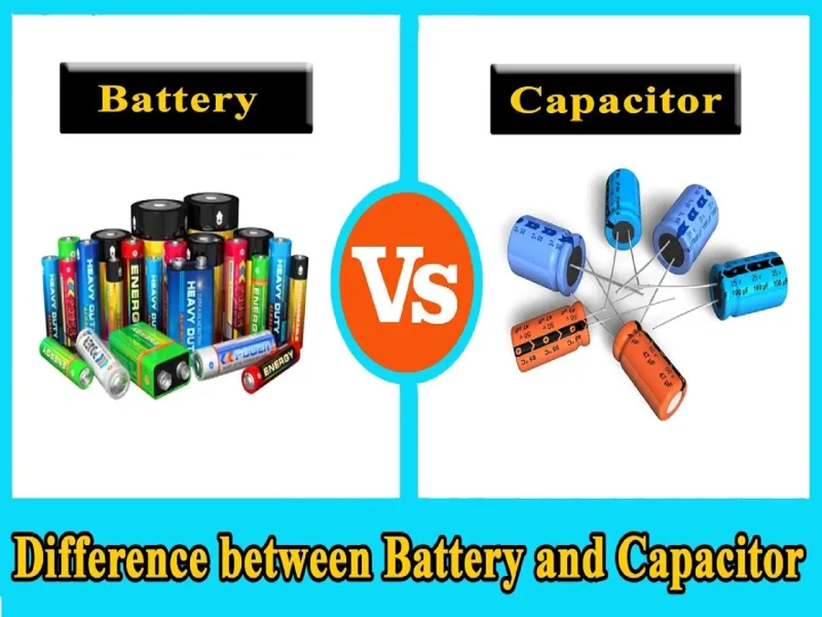
Understanding the nuances between different capacitor codes is essential for proper circuit design. While the 103 capacitor is characterized by its 10 nF (0.01 µF) capacitance, comparing it to other common codes such as 102, 104, and 223 reveals significant differences in capacitance, application, and voltage ratings that inform crucial design choices.
| Capacitor Code | Capacitance Value | Typical Application | Notes |
|---|---|---|---|
| 102 | 1,000 pF (1 nF or 0.001 µF) | High-frequency filtering, timing circuits | Smaller capacitance suited for sensitive circuits. |
| 103 | 10,000 pF (10 nF or 0.01 µF) | General decoupling, filtering | Widely used general purpose capacitor. |
| 104 | 100,000 pF (100 nF or 0.1 µF) | Power supply decoupling, noise reduction | Higher capacitance for more robust filtering. |
| 223 | 22,000 pF (22 nF or 0.022 µF) | Signal coupling, frequency tuning | Mid range applications for signal coupling. |
This section addresses common queries regarding 103 capacitors, providing concise and authoritative answers to assist with selection and application.
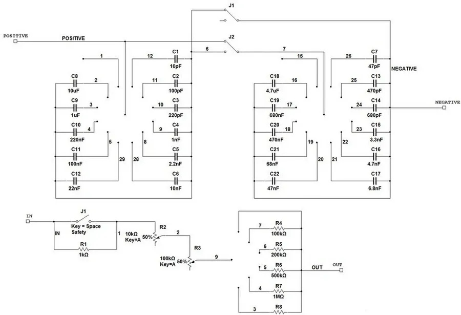
Choosing the appropriate 103 capacitor for a specific application requires careful consideration of several key parameters beyond its nominal capacitance value. These include voltage rating, tolerance, temperature coefficient, and physical dimensions, all of which impact performance and reliability within a circuit.
The 103 capacitor, though seemingly small, is a powerful element in the world of electronics. Whether you are a seasoned engineer or a hobbyist, understanding its value and function is crucial for effective circuit design and repair. With its 10nF capacitance, the 103 capacitor plays an integral part in countless devices that enhance our daily lives and enable technological advances. Remember to always select the correct component for your application, taking into account not just capacitance but voltage and material, to ensure reliability and performance.

