Imagine your electronics as a finely tuned orchestra. Sometimes, unwanted noise creeps in, like a discordant note. That's where filter capacitors step in, acting like the conductor who eliminates these disturbances. These unsung heroes of electronic circuits, like the ones in the power supply of your phone, quietly smooth out voltage fluctuations and remove unwanted frequencies, ensuring a clean and stable performance. This article delves deep into the world of filter capacitors, uncovering their purpose, types, selection process, and how they're vital in various applications, impacting everything from household appliances to complex industrial machinery.
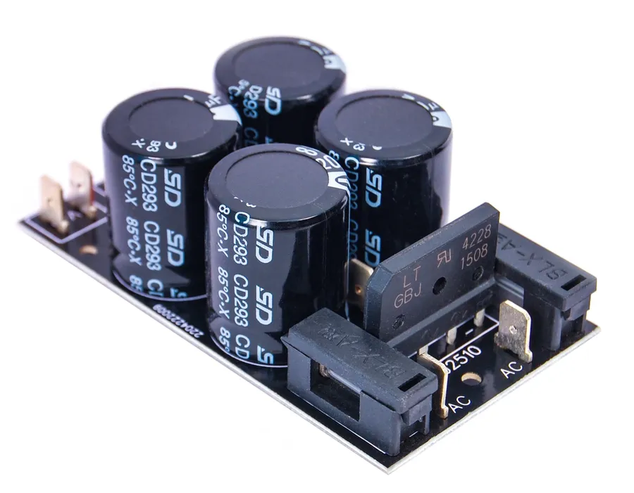
A filter capacitor, at its core, is an electronic component engineered to selectively manage the flow of alternating current (AC) and direct current (DC) within a circuit. Its primary function is to 'filter' out unwanted frequencies or smooth voltage fluctuations. This is achieved by exploiting the capacitor's fundamental property of storing electrical charge, which manifests as a frequency-dependent impedance.
The core principle is that capacitors exhibit high impedance to low-frequency signals (including DC) and low impedance to high-frequency signals. Consequently, when a mixed AC and DC signal is applied, a filter capacitor will impede the DC component (effectively blocking it) while allowing the AC component to pass. Furthermore, when incorporated into smoothing circuits in power supplies, filter capacitors store energy during voltage peaks and release it during dips, thereby reducing ripple and achieving a steadier output voltage. This mechanism relies on the charge-storing behavior of the capacitor and its relationship to the frequency of the applied voltage.
The ability of a filter capacitor to selectively allow certain frequencies to pass while impeding others stems directly from its inherent capacity to store electrical charge. This storage capability, coupled with the capacitor's impedance characteristics, forms the core of its filtering function.
At a fundamental level, a capacitor consists of two conductive plates separated by a dielectric material. When a voltage is applied across these plates, electric charge accumulates, creating an electric field and storing energy. This stored energy can then be released, which impacts the behavior of alternating current (AC) signals as they pass through the capacitor. The relationship between the voltage across the capacitor and the charge stored is described by the equation: Q = CV, where Q is charge, C is capacitance, and V is voltage.
The effectiveness of a capacitor as a filter is dictated by its impedance, which is the opposition to the flow of alternating current. The impedance of an ideal capacitor is inversely proportional to the frequency of the signal. This relationship is represented by the formula: Z = 1 / (2πfC), where Z is impedance, f is frequency, and C is capacitance. This equation highlights that capacitors offer low impedance to high-frequency AC signals and high impedance to low-frequency AC signals, effectively blocking direct current (DC). As the frequency of the signal increases, the capacitor's impedance decreases, allowing high-frequency signals to pass more easily. Conversely, lower frequency signals and DC encounter higher impedance, and are therefore blocked or significantly attenuated.
The frequency-dependent impedance is critical for the filtering process. In a typical application, filter capacitors are employed to smooth out variations in a power supply's output. When used in conjunction with a rectifier circuit, capacitors are used to remove the AC ripple and provide a stable DC output. The capacitors charge during the rising portion of the AC wave and discharge during the falling portion, effectively filling in gaps and maintaining a consistent voltage. In high-frequency applications, capacitors can filter out unwanted noise. This selective impedance characteristic makes capacitors versatile and important in a wide array of filtering applications.
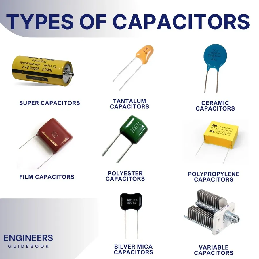
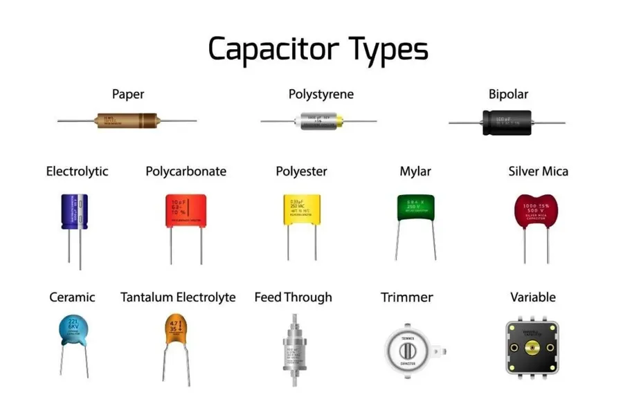
Filter capacitors are not monolithic; they come in various types, each with unique characteristics that make them suitable for specific filtering applications. Understanding these differences is crucial for effective circuit design and performance. The selection depends heavily on the frequency range, voltage requirements, and environmental conditions.
| Capacitor Type | Material Composition | Typical Capacitance Range | Voltage Rating | ESR (Equivalent Series Resistance) | Temperature Stability | Primary Applications |
|---|---|---|---|---|---|---|
| Electrolytic | Aluminum or Tantalum with electrolyte | 1 µF to > 10,000 µF | Low to High (up to 500 V for aluminum, up to 100V for tantalum) | Moderate to High | Moderate | Power supply smoothing, low-frequency filtering |
| Ceramic | Ceramic dielectric material | 1 pF to 100 µF | Low to Moderate (typically < 100 V) | Low | Good | High-frequency filtering, decoupling |
| Film | Plastic film dielectric (polyester, polypropylene) | 1 nF to 10 µF | Moderate to High (up to kV levels) | Low | Good to Excellent | Audio signal processing, high-voltage filtering |
Each capacitor type exhibits specific advantages and limitations that must be considered when choosing for a particular application. Electrolytic capacitors are favored for their high capacitance values, but generally, they have higher ESR, limited temperature range and lower lifespan. Ceramic capacitors offer low ESR and good high-frequency performance, however, they provide lower capacitance. Film capacitors provide excellent stability, low losses, and durability.
The choice of a filter capacitor significantly impacts circuit performance. For example, for smoothing the rectified output of a power supply, electrolytic capacitors with high capacitance are commonly used. In contrast, high-frequency bypass applications often employ ceramic capacitors for their low impedance at high frequencies.
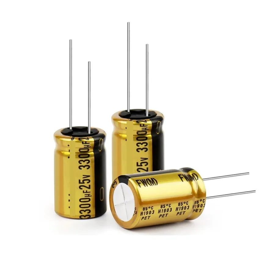
Filter capacitors are indispensable components in a wide array of electronic applications, leveraging their ability to selectively pass or block frequencies for noise reduction, signal conditioning, and power smoothing. Their versatility makes them essential in diverse fields, from power electronics to audio engineering.
Here are some specific examples of filter capacitor applications:
These applications demonstrate the essential role that filter capacitors play across a variety of electronic systems. The precise use of these components can be quite complex as the performance will vary depending on several factors, such as the capacitor type, voltage rating, frequency response, and quality factor, and must be chosen with careful consideration.
Selecting the correct filter capacitor is crucial for optimal circuit performance. This involves careful consideration of several key parameters, including voltage rating, capacitance value, frequency range, tolerance, and temperature characteristics. Each parameter has a significant impact on the filter's effectiveness and the overall reliability of the system.
| Parameter | Description | Impact on Performance | Considerations |
|---|---|---|---|
| Voltage Rating | Maximum voltage the capacitor can safely handle. | Exceeding the voltage rating can lead to capacitor failure (short circuit or open circuit) and may damage the circuit. | Select a capacitor with a voltage rating significantly higher than the maximum expected voltage in the application (e.g., 20% higher is a common practice). |
| Capacitance Value | The ability to store electrical charge. | Determines the filtering effectiveness; higher capacitance offers more charge storage and better low-frequency filtering. | Choose the capacitance value based on the desired cut-off frequency and the impedance of the load. Consider the formula f = 1/(2*pi*R*C) where f is frequency, R is resistance and C is capacitance. |
| Frequency Range | The range of frequencies the capacitor is designed to filter. | Capacitors are more effective at filtering at certain frequencies. Performance degrades as you move away from the designed frequency range. | Select a capacitor type designed for the frequency range of your application (e.g., ceramic capacitors for high-frequency, electrolytic capacitors for low-frequency). |
| Tolerance | The allowable deviation from the stated capacitance value. | Affects the accuracy of the filter performance. Wide tolerance can cause filter to perform out of specification | Select the correct tolerance depending on precision requirements of the design. Tighter tolerance capacitors are more expensive. |
| Temperature Characteristics | How the capacitor's parameters change with temperature. | Capacitance and ESR are influenced by temperature; performance can degrade as temperatures rise or fall | Ensure that the capacitor operates effectively within the expected temperature range of your application. Choose capacitor with lower drift over a wide temperature range. |
In addition to the above parameters, consider the practical aspects of selection, such as capacitor size constraints and the lead type needed to mount the component to the circuit board. Cost is also a key consideration in mass-produced designs. Ensure capacitors are from a reputable manufacturer to ensure consistent quality and reliability.
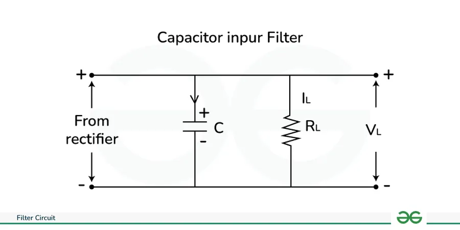
Proper integration of filter capacitors within a circuit is crucial for optimal performance. This involves strategic decisions regarding series or parallel configurations, physical placement relative to the components they are intended to filter, and understanding the potential adverse effects of poor design choices. These factors significantly impact the effectiveness of filtering and the overall stability of the circuit.
Filter capacitors are generally employed in two primary configurations: series and parallel, each serving distinct functions. Parallel configurations, where the capacitor is placed in parallel with the load, are most common for filtering applications. In this arrangement, the capacitor shunts high-frequency noise to ground, preventing it from reaching the load. Series configurations, while less common for typical filtering, can be utilized in specific scenarios, such as impedance matching or in resonant circuits. Understanding the impedance characteristics of the circuit is key to selecting the optimal arrangement.
| Configuration | Circuit Arrangement | Primary Function | Common Application |
|---|---|---|---|
| Parallel | Capacitor connected parallel to the load | Shunting high frequency noise to ground | Power supply smoothing, decoupling |
| Series | Capacitor connected in series with the load | Impedance matching or creating resonant circuit | Tuned circuits, specialized filtering |
The physical placement of filter capacitors is paramount to their effectiveness. To minimize the path impedance for high-frequency currents, the filter capacitor should be placed as close as physically possible to the component it is intended to filter, this often means placing a decoupling capacitor close to the power pin of an IC. This minimizes the parasitic inductance of the connecting traces and wires, which can limit the capacitor’s ability to shunt high-frequency noise. Proper grounding is equally important, a poorly grounded capacitor is ineffective as it can't shunt current effectively. Long traces between the capacitor and the ground return path increase impedance, diminishing its filtering capabilities.
Poor placement and design choices can lead to significant degradation in the performance of a filter capacitor. Excessive trace lengths to the capacitor can significantly reduce the effectiveness of high-frequency noise suppression. Additionally, improper grounding techniques, such as sharing ground paths with noisy circuitry, can introduce noise back into the system. Failure to select the proper capacitor based on the specific parameters of the application, including voltage rating, capacitance value, ESR and temperature characteristics, can also result in unreliable or ineffective filtering. These design and placement errors can lead to increased noise levels, reduced circuit performance, and even component failure.
Filter capacitors, while essential for circuit stability and performance, are prone to various failure modes that can compromise electronic device functionality. Identifying these issues early and understanding their root causes is crucial for effective troubleshooting and maintenance. This section provides a guide to common problems, diagnostic methods, and replacement strategies, ensuring optimal circuit operation.
| Symptom | Possible Causes | Diagnostic Method | Remedy |
|---|---|---|---|
| Bulging Case | Overvoltage, overheating, reverse polarity | Visual Inspection | Replace capacitor immediately |
| Leaking Electrolyte | Seal Damage, internal pressure | Visual Inspection | Replace capacitor immediately |
| Performance Degradation | Temperature, Aging | ESR Meter, LCR Meter | Replace capacitor |
| Open Circuit | Internal Damage, physical disconnection | Continuity Test with Multimeter | Replace capacitor |
| Short Circuit | Dielectric Breakdown | Resistance Test with Multimeter | Replace capacitor immediately |
When replacing a filter capacitor, ensure that the new component has at least the same voltage rating and capacitance value as the original. Consider selecting a capacitor with a higher temperature rating for added reliability in demanding environments, also considering the physical size of the capacitor to make sure it fits the space provided on the PCB. It is advisable to replace capacitors in pairs or groups, especially in critical filtering circuits to ensure consistency and long-term reliability.
This section addresses common queries regarding filter capacitors, providing clear and concise answers to help you understand their function, applications, and potential issues.
While all filter capacitors are indeed capacitors, not all capacitors function as filters. The distinction lies in their intended application and the specific electrical properties that facilitate that use. A standard capacitor is a passive two-terminal electrical component used to store energy electrostatically in an electric field. A filter capacitor is specifically used to attenuate unwanted frequencies within an electronic circuit. Their effectiveness as filters is determined by the capacitor's inherent properties, such as capacitance, equivalent series resistance (ESR), and parasitic inductance, along with circuit configuration.
| Feature | Filter Capacitor | Standard Capacitor |
|---|---|---|
| Primary Function | Specifically designed to attenuate or block certain frequencies | General energy storage, coupling, decoupling |
| Frequency Response | Optimized for specific frequency ranges, characterized by low ESR and ESL at intended frequencies | Broader frequency response, not necessarily optimized for filtering |
| Application | Power supply smoothing, signal filtering, noise reduction | Energy storage, timing circuits, coupling, decoupling |
| ESR/ESL Consideration | Low ESR and ESL are crucial to maintain filtering efficacy at designed frequencies | ESR/ESL is often less critical for general capacitor applications |
| Usage Context | Typically placed in circuit where filtering of frequencies is essential | Used as general passive components throughout most circuits |
| Parameter Importance | Capacitance value, ESR, ESL, and frequency response are key parameters | Capacitance is often the primary parameter of interest |
Filter capacitors, though often small and overlooked, are integral to the smooth and reliable operation of countless electronic devices. They efficiently remove unwanted signals and provide stability in electronic circuits. From power supplies in our phones to noise reduction in complex industrial machinery, filter capacitors ensure clean, efficient, and dependable performance. By understanding their function, the various types, their applications, and how to properly select them, engineers and enthusiasts alike can harness the full potential of these electronic components. The filter capacitor is not just a passive component; it's an active guardian of signal integrity in the electronic world, continually evolving and adapting with advancing technologies.

