Just like a city map guides you through its streets, the Arduino Uno pin layout is the key to navigating the world of microcontrollers. Imagine the Arduino as a miniature city, and each pin is a street corner leading to different functionalities. Understanding this layout is crucial for any maker, enabling you to connect sensors, actuators, and other electronic components to your board. This article will serve as your detailed map, helping you understand every corner of the Arduino Uno, from its digital and analog I/O to power and communication pins.
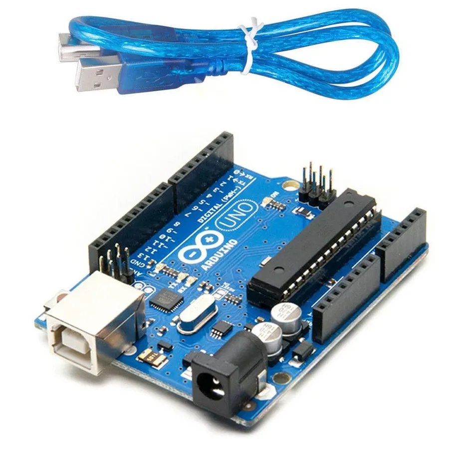
The Arduino Uno, a cornerstone of embedded systems and DIY electronics, is built around the ATmega328P microcontroller, operating at a clock speed of 16 MHz. This microcontroller, with its integrated memory, provides the computational power for a wide array of projects. The board's design focuses on accessibility and ease of use, making it ideal for beginners while still catering to more complex project needs.
| Feature | Specification |
|---|---|
| Microcontroller | ATmega328P |
| Clock Speed | 16 MHz |
| Operating Voltage | 5V |
| Digital I/O Pins | 14 (6 with PWM) |
| Analog Input Pins | 6 |
| Flash Memory | 32 KB |
| SRAM | 2 KB |
| EEPROM | 1 KB |
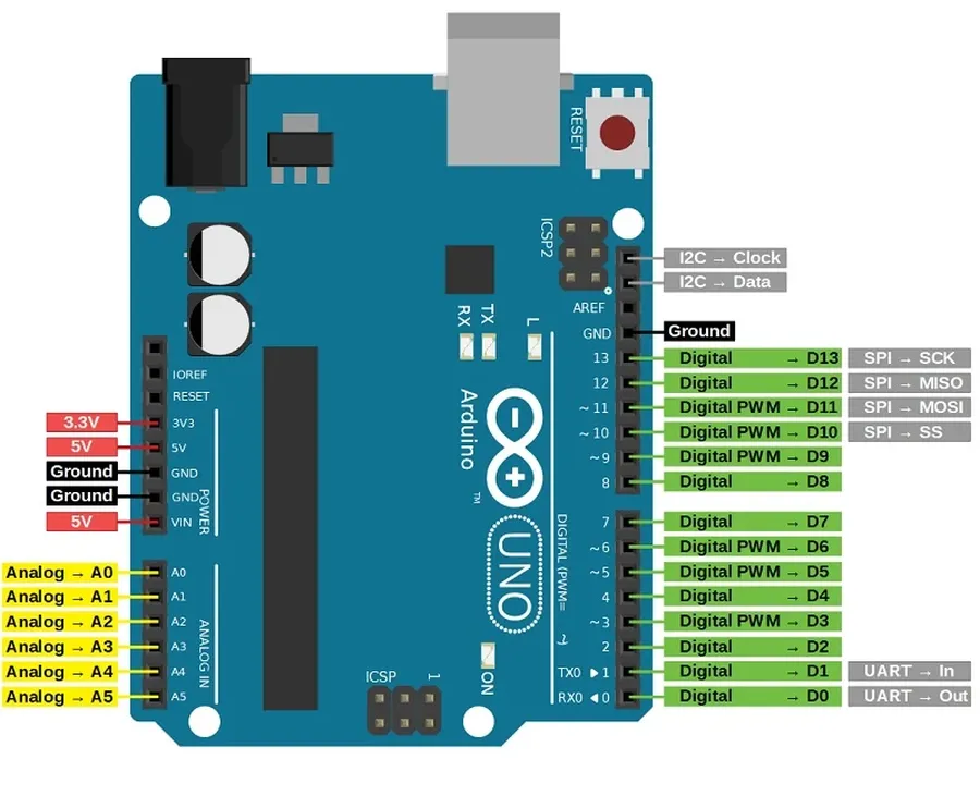
The Arduino Uno features 14 digital input/output (I/O) pins, numbered from 0 to 13. These pins are the fundamental interface for interacting with the external world, enabling the Arduino to receive signals from sensors and control actuators. Each pin can be configured as either an input or an output, providing versatility in project design. The core functions for utilizing these pins are `digitalWrite()` to send signals and `digitalRead()` to receive signals.
| Pin Number | Function | Description | Special Features |
|---|---|---|---|
| 0 (RX) | Digital I/O / Serial Receive | Used for receiving serial data; also a standard digital I/O pin. | Serial communication receive pin. |
| 1 (TX) | Digital I/O / Serial Transmit | Used for transmitting serial data; also a standard digital I/O pin. | Serial communication transmit pin. |
| 2-13 | Digital I/O | General-purpose digital I/O pins that can be used as either inputs or outputs. | Some pins also have PWM capabilities. |
| 3, 5, 6, 9, 10, 11 | Digital I/O / PWM | These pins support Pulse Width Modulation (PWM) for analog-like outputs. | Used to control motor speeds and LED brightness. |
The digital pins can operate in two states: HIGH (5V) or LOW (0V). When configured as inputs, these pins detect the state of an external signal. When set as outputs, they can drive external components by providing or stopping voltage. This binary control is fundamental for most digital interactions. The `digitalWrite(pin, value)` function sets a specified digital pin to either HIGH or LOW while the `digitalRead(pin)` function retrieves the state of a digital pin, returning either HIGH or LOW. Understanding and utilizing these functions effectively is key to using the Arduino's digital capabilities.
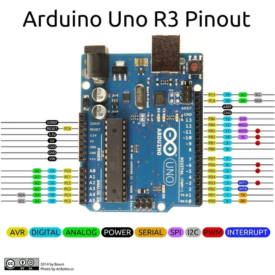
The Arduino Uno is equipped with six analog input pins, labeled A0 through A5, which enable the board to interface with the analog world. Unlike digital pins, which only recognize two states (HIGH or LOW), analog pins can read a continuous range of voltage levels. This capability is essential for applications that require interaction with analog sensors, such as potentiometers, temperature sensors, and light sensors.
These pins convert the incoming analog voltage into a digital value that the Arduino's microcontroller can understand using an Analog-to-Digital Converter (ADC). The Arduino Uno's ADC has a 10-bit resolution, meaning it can represent 2^10 (1024) discrete levels of voltage. This allows it to measure analog voltages with a decent degree of precision, providing a digital value ranging from 0 to 1023. The reference voltage for this conversion is typically 5V, meaning a reading of 0 corresponds to 0V, and a reading of 1023 corresponds to 5V. The voltage corresponding to any digital reading can be calculated using the formula: Voltage = (reading * 5.0) / 1023
| Feature | Description |
|---|---|
| Number of pins | 6 (A0 to A5) |
| Function | Measure analog voltage levels |
| Voltage Range | 0V to 5V (default) |
| ADC resolution | 10-bit (1024 discrete levels) |
| Function | Used with analog sensors, such as potentiometers, temperature sensors, etc. |
| Code Function | Reading the analog values by using the `analogRead(pin)` function, which returns an integer in the range of 0-1023. |
The `analogRead()` function is used to read the analog voltage applied to a specified analog input pin, which returns an integer between 0 and 1023, representing the corresponding voltage value scaled to the ADC's resolution. Here is a example code using a potentiometer :
// Potentiometer connected to analog pin A0
const int potentiometerPin = A0;

void setup() {
  Serial.begin(9600);
}

void loop() {
  // Read the analog value from the potentiometer
  int sensorValue = analogRead(potentiometerPin);

  // Print the raw value to the serial monitor
  Serial.print("Raw Value: ");
  Serial.print(sensorValue);

  // Calculate the voltage from 0V to 5V
  float voltage = sensorValue * (5.0 / 1023.0);
  Serial.print(", Voltage: ");
  Serial.print(voltage);
    Serial.println("V");

  delay(100);  // Delay for 100 milliseconds
}
This code reads the analog voltage on pin A0. The voltage value is calculated from the sensor reading, and the serial output displays both the raw 10-bit ADC value, and the corresponding voltage. By modifying the code, you can use this method to connect to a wide variety of analog sensors and take readings from them.
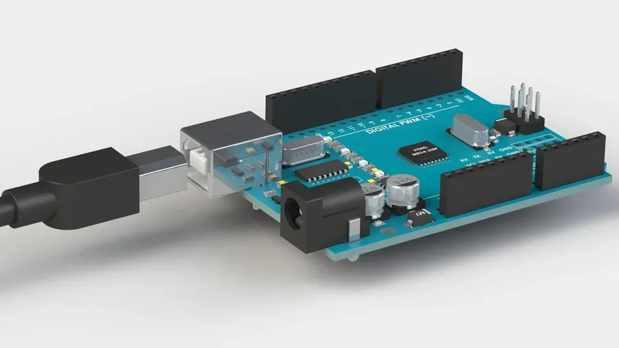
The Arduino Uno's power pins are crucial for providing the necessary electrical energy to both the board itself and any connected external components. These pins include VIN, 5V, 3.3V, and GND, each serving a distinct role in the power distribution network of the device. Understanding these pins is essential for ensuring that your circuits are powered correctly and to avoid potential damage due to improper power connections.
| Pin | Description | Voltage | Use Cases | Considerations |
|---|---|---|---|---|
| VIN | Voltage Input | 7-12V | Powering the Arduino board when using an external power supply. | Ensure that the input voltage is within the acceptable range. Avoid exceeding the recommended maximum voltage. |
| 5V | 5 Volt Output | 5V | Supplying power to external components requiring 5V, such as sensors or small circuits. | Do not draw more current than the Arduino can safely provide (Typically around 500mA). Exceeding the current limits can cause damage. |
| 3.3V | 3.3 Volt Output | 3.3V | Supplying power to external components requiring 3.3V, such as some sensors and modules. | Similar to the 5V pin, be mindful of current limits. The 3.3V pin can supply less current than the 5V pin. |
| GND | Ground | 0V | Common ground reference for both the Arduino and connected circuits. | Always connect the ground of external components to the GND pin. Ensures proper circuit functionality. |
When using external power supplies, the VIN pin allows the use of a 7-12V source, which the Arduino's on-board regulator will then reduce to 5V for internal use. When powering the board through the USB port, this 5V is also available on the 5V pin. However, care must be taken when powering external devices from the 5V pin to ensure that you do not draw more current than the Arduino board can safely supply. The 3.3V pin is useful for powering low-voltage devices, but it has even lower current limitations. The GND pins are fundamental reference points that all components need to function properly and must be connected in all external circuits.
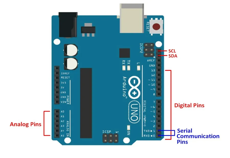
Beyond the typical digital and analog I/O pins, the Arduino Uno incorporates specialized pins that serve critical functions for board control, analog reference adjustments, and programming. These special function pins, while fewer in number, are essential for comprehensive project development and debugging capabilities. The Reset pin allows for manual board restarts, the AREF pin is used to set an external analog reference voltage, and the ICSP header provides an interface for in-circuit serial programming.
| Pin Name | Function | Description |
|---|---|---|
| RESET | System Reset | Brings the microcontroller back to its initial state. A low signal on this pin triggers a reset. |
| AREF | Analog Reference | Allows for an external voltage to be used as the reference voltage for analog-to-digital conversion. This can be important for more accurate analog readings in specific situations. |
| ICSP Header | In-Circuit Serial Programming | Used to program the microcontroller directly without using the USB serial interface. This is beneficial when the bootloader is compromised or needs to be replaced. |
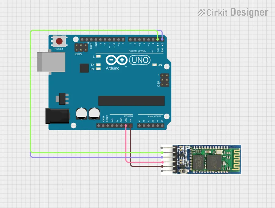
The Arduino Uno leverages several communication interfaces to interact with other devices and peripherals, extending its capabilities beyond simple input and output. These interfaces include Serial, SPI (Serial Peripheral Interface), and I2C (Inter-Integrated Circuit), each catering to different communication needs and complexities.
Understanding these communication protocols is crucial for developing sophisticated Arduino projects that involve interactions with a wide range of sensors, displays, and other microcontrollers.
| Interface | Pins | Description | Use Cases |
|---|---|---|---|
| Serial | RX (Pin 0), TX (Pin 1) | Asynchronous communication, commonly used for debugging and interfacing with computers or other serial devices. | Data logging, basic communication with computers, GPS modules. |
| SPI | SS (Pin 10), MOSI (Pin 11), MISO (Pin 12), SCK (Pin 13) | Synchronous, high-speed serial communication, ideal for interfacing with memory chips, sensors, and displays that support SPI. | SD card readers, LCD displays, high-speed data transfer. |
| I2C | SDA (A4), SCL (A5) | Two-wire, synchronous serial communication protocol. It is suitable for connecting multiple devices using the same two wires. | Real-time clock modules, temperature sensors, small displays with I2C interface. |
Each of these interfaces has specific advantages and is suitable for different types of communication requirements. Selecting the right interface is critical for designing efficient and reliable projects. Consider the speed, number of devices, and distance of communication when deciding which interface to use.
This section addresses common questions regarding the Arduino Uno pin layout, aiming to clarify the functionality and usage of various pins. Understanding these aspects is crucial for effective Arduino project development. The following questions cover essential pin categories and their roles in basic and advanced applications.
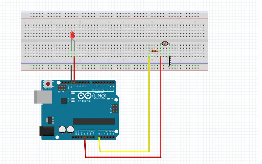
The Arduino Uno's true power is unlocked when it interfaces with the physical world through sensors and actuators. This section provides tangible examples, demonstrating how to connect these components using the Arduino's various pins. We will explore basic circuit diagrams and code snippets to illustrate how to bring sensor data into the digital realm and translate digital commands into physical actions.
These examples provide a foundation for more complex projects. By combining these techniques with the knowledge of digital, analog, and power pins discussed earlier, users can create a wide variety of interactive devices and systems.
| Component | Arduino Pin | Description |
|---|---|---|
| LED | Digital Pin (e.g., Pin 13) | Output; for simple light emission control. |
| TMP36 Temperature Sensor | Analog Pin (e.g., A0) | Input; Reads analog voltage that's proportional to temperature. |
| Servo Motor | Digital PWM Pin (e.g., Pin 9) | Output; Controls the angular position of the servo's arm. |
| HC-SR04 Ultrasonic Sensor | Digital Output (Trig) / Input (Echo) pins | Used to measure distance using sound. |
While the Arduino Uno's pins serve specific primary functions, advanced techniques like pin multiplexing and interrupts unlock further capabilities. These techniques allow for more complex interactions and efficient resource utilization, though they require a deeper understanding of the microcontroller's inner workings and embedded programming principles.
Pin multiplexing enables multiple functionalities to share a single physical pin, by toggling rapidly between the functions. For instance, some digital pins can serve as PWM outputs, SPI communication pins, or general-purpose I/O pins, this is possible through a process known as multiplexing and this ability to serve multiple functions is controlled by configuring registers within the microcontroller.
Interrupts, on the other hand, allow the microcontroller to respond to specific events asynchronously rather than constantly monitoring the pins. This means that the microcontroller can execute normal code until an interrupt occurs (such as the pin changing from high to low), when it will then jump to a specific interrupt handler. This can help to create code that is more responsive to external events and increases efficiency by not having to actively poll for specific changes on pins.
It is important to understand that these features are available on the Arduino Uno; however, the implementation requires a deeper knowledge of the microcontroller itself and these can not be implemented using the basic Arduino IDE interface, and they should be used with care to ensure that there is no conflict in the code or the connections.
The Arduino pins layout, much like the blueprints of a building, is fundamental to understanding and utilizing the Arduino Uno board. Mastering the digital, analog, power, and communication pins not only enables you to bring your creative electronic projects to life, but also to delve deeper into the vast world of embedded systems. From simple LED circuits to complex sensor networks, the Arduino Uno’s pins are your gateway to the world of making and the internet of things. As you continue to explore and innovate, remember that a strong foundation in the basics, like pin function and proper layout, is critical to every successful creation and to push your project to its full potential.

