The ZVex Fuzz Factory, a legendary fuzz pedal, is renowned for its unpredictable and wild tones. Its unique circuit design often sparks curiosity among DIY pedal enthusiasts. Understanding the Fuzz Factory layout is crucial for those wanting to build, modify, or troubleshoot this iconic pedal. We'll delve into various layouts, explain their nuances, and provide a comprehensive understanding of this chaotic circuit, and finally, empower you to embark on your own fuzz factory journey.
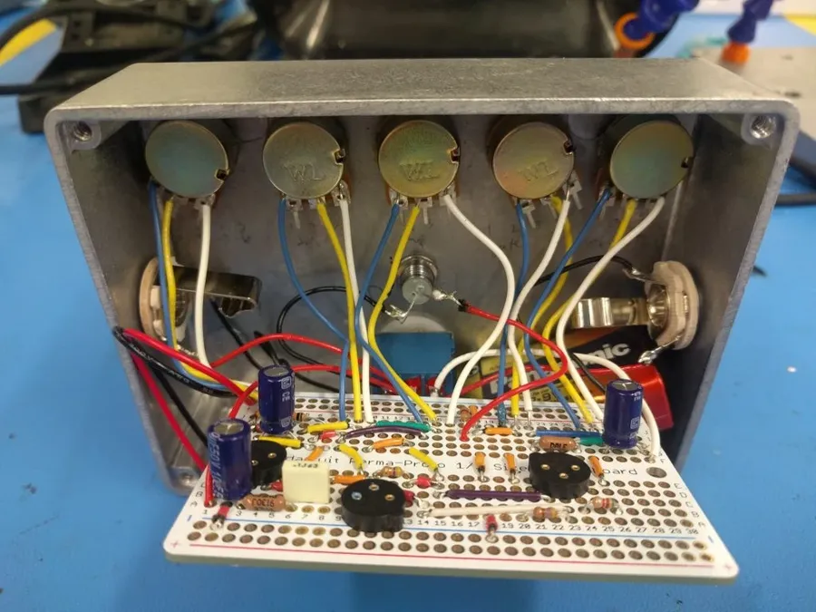
The Fuzz Factory's distinctive and chaotic sound is born from the interaction of a few key components: germanium transistors, potentiometers (pots), and capacitors. These parts, when combined within a specific circuit, create the highly responsive and unstable fuzz that defines the pedal. Each component, with its unique role, contributes to the wide range of tones and the pedal's sensitivity to input.
Germanium transistors, critical to the Fuzz Factory's character, introduce specific non-linear behaviors that greatly contribute to the pedal's sound. Potentiometers provide variable resistance, allowing the user to finely tune parameters such as oscillation, gate, and compression, offering a rich array of tonal possibilities. Capacitors are utilized for filtering and shaping the frequency response, further influencing the overall sound of the pedal by controlling the tonal qualities and the gain structure.
| Component | Role in Fuzz Factory | Impact on Sound |
|---|---|---|
| Germanium Transistors | Amplification and signal distortion | Introduce unique non-linear distortion and contribute to the pedal's characteristic fuzz. |
| Potentiometers (Pots) | Variable resistance for parameter control | Allow users to control gain, oscillation, gate, and compression, greatly altering the tone and behavior. |
| Capacitors | Filtering and frequency shaping | Shape the overall frequency response, filtering specific frequencies and altering the tonal character of the fuzz. They also impact the gain structure. |
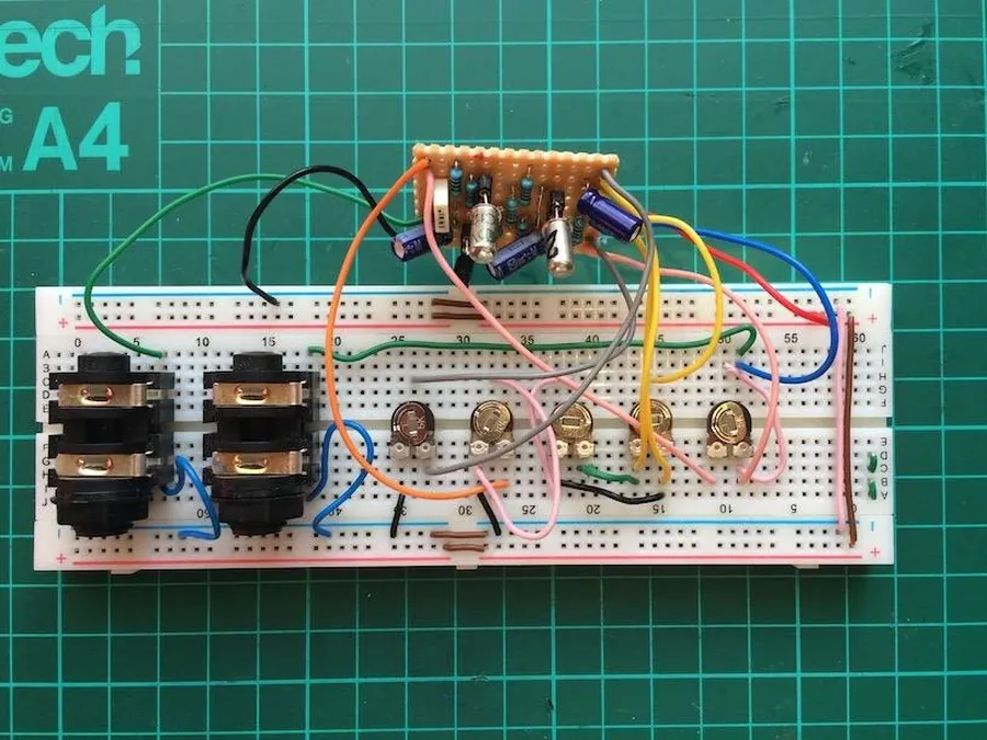
The original ZVex Fuzz Factory layout is characterized by its distinctive component arrangement, a design choice driven by both sonic and practical considerations. This layout, while seemingly unconventional, contributes significantly to the unique and often unpredictable tonal character of the pedal. The positioning of components is not arbitrary but rather a careful configuration that encourages specific interactions within the circuit.
The core of the original Fuzz Factory centers around two germanium transistors, often NPN type. These transistors are highly sensitive and their gain characteristics are greatly influenced by the surrounding circuitry. The layout, often not optimized for the shortest possible signal path, instead prioritizes component interaction to achieve the intended range of fuzz and oscillation. Unlike modern PCB layouts, the original often featured a more organic, hand-wired approach.
Key features of the original layout include the use of point-to-point wiring or stripboard construction with components spaced to allow for a degree of 'component bleed' which contributes to the unstable and dynamic character of the pedal. Potentiometers, in particular, are placed in a way that makes their interaction highly influential, leading to the erratic yet musical behavior the Fuzz Factory is famous for. The capacitance and resistance values across the circuit create dynamic and complex interactions, and the component spacing contributes to that effect.
Understanding the original ZVex Fuzz Factory layout is essential for those seeking to replicate its exact sonic qualities or appreciate the design philosophy behind it. It is not just a question of placing components but about how those components are placed to maximize specific nonlinearities and interactions. The unique configuration, with its slightly chaotic appearance, is crucial to the Fuzz Factory’s distinctive performance. This inherent instability is a core component of the pedal’s character, which is why exact replication is sought after by many DIY enthusiasts.
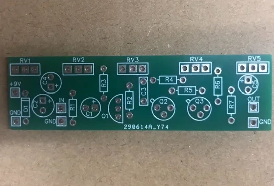
The inherent complexity of the Fuzz Factory circuit, with its five potentiometers and multiple transistors, often leads to large enclosures. However, compact layouts address this by optimizing the component arrangement to fit within smaller enclosures, most commonly the 1590B enclosure, without compromising the core functionality and sonic characteristics of the pedal. These designs are crucial for pedal builders who prioritize space efficiency on their pedalboards.
Compact layouts achieve their reduced footprint through several strategies. Component selection plays a crucial role, with the use of smaller capacitors and resistors being common. The arrangement of potentiometers and transistors is also optimized, placing them closer together and, where possible, using vertical mounting or stacked components. Furthermore, the layout often minimizes the use of large amounts of wiring by strategically placing components to allow for direct connections.
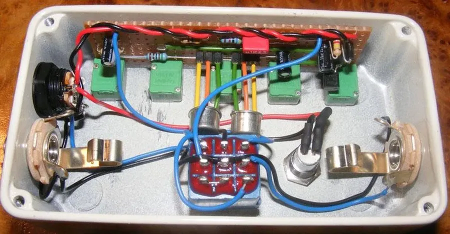
Optimizing for the 1590B enclosure has become a focus due to its compact size and popularity among DIY pedal builders. These enclosures demand precise layout planning, often involving custom PCBs or carefully laid out Vero board designs to maximize the usable space. Specific attention is given to the spacing around mounting hardware and the height of components to ensure they don't interfere with the enclosure.
The main advantages of compact layouts are the reduced size for easier pedalboard integration, ease of handling when building and a lower material usage which can reduce overall cost. On the other hand, the challenges associated with compact builds include the higher precision required for assembly, increased component density which can make troubleshooting more difficult, and potential for signal noise if layout is not carefully thought out.
When constructing a Fuzz Factory, the choice between Vero board (stripboard) and Printed Circuit Board (PCB) layouts significantly impacts the building process, signal integrity, and overall project suitability. Each method presents unique advantages and disadvantages that must be carefully considered based on the builder's experience and project requirements. This section will provide a structured comparison to aid in making an informed decision.
| Feature | Vero Board (Stripboard) | PCB |
|---|---|---|
| Ease of Building | Generally easier for beginners due to its straightforward layout and minimal specialized equipment; requires more careful attention to avoiding shorts through proper cuts. | Can be more complex to assemble initially if not using a through-hole kit, but once all parts are in place, it has an easier, more consistent build process; typically designed to minimize assembly errors. PCBs designed for SMT components require more specialized equipment |
| Signal Integrity | Prone to parasitic capacitance and less controlled impedance, which can impact the circuit's performance, especially in high-gain scenarios, if not constructed carefully. In general, it's more susceptible to environmental noise. | Offers superior signal integrity due to controlled trace impedance and layout optimization, which leads to less noise, parasitic capacitance, and better performance in high-gain scenarios, if the circuit is well designed. PCBs usually have ground planes that make them less susceptible to environmental noise. |
| Component Density | Relatively lower component density due to the fixed grid spacing, which can make compact layouts challenging, and more prone to short-circuits if not carefully planned out. | Higher component density is achievable, making it suitable for compact enclosures; can accommodate surface mount components for even greater density. |
| Customization | Highly customizable, allowing for easy modifications and experimentation with component values; easy to build single prototypes or small batches. | Less customizable after fabrication, but provides more accurate and consistent results for larger batches; often requires redesign if significant modifications are needed. |
| Cost | Lower upfront cost for materials and tools, especially for one-off builds; ideal for prototyping and testing. Typically uses commonly available components. | Higher initial cost due to fabrication, but can be cost-effective for larger runs; has a wider component selection, but it can also be pricier. |
| Suitability | Best for one-off projects, learning, or small modifications; good for experimenting with different sounds; easier to repair. | Best for larger production runs, or for those who require reliability and consistent performance; offers greater durability. |
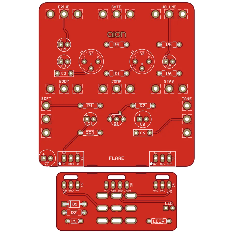
Analyzing the Fuzz Factory schematic provides crucial insights into its signal flow and component interaction, essential for builders seeking a comprehensive understanding of this unique pedal. A deep dive into the schematic illuminates the nonlinearities inherent in the design, which are responsible for the wide range of chaotic and unpredictable sounds it can produce. This section is specifically tailored to help builders effectively interpret the schematic.
The Fuzz Factory circuit is based around a three-transistor topology, with each transistor stage contributing to the complex distortion and oscillation characteristics. Understanding the role of each stage is essential for effective building and troubleshooting.
Key aspects for builders when interpreting the schematic include tracing the signal path from the input jack through the transistors and finally to the output jack. This process helps in comprehending how each control interacts with the signal and shapes the final sound. Identifying the critical feedback paths will allow builders to understand the complex interactions that leads to the unique sound of the Fuzz Factory.
| Component | Function | Impact on Tone |
|---|---|---|
| Transistors (Q1, Q2, Q3) | Signal amplification and clipping | Determines gain, distortion and oscillation characteristics |
| Capacitors (C1, C2, etc.) | Frequency shaping and coupling | Controls bass response, oscillation and overall tone |
| Potentiometers | Variable resistance for biasing and signal control | Adjusts gain, feedback, and allows for wide range of sonic possibilities |
| Resistors (R1, R2, etc.) | Bias setting and current limiting | Determines operating point of transistors and impedance of the circuit |

The Fuzz Factory, while iconic in its raw form, is often modified to further tailor its sound. These modifications range from subtle tweaks to radical alterations, each influencing the pedal's sonic character. These adjustments often center around adding tone controls, altering gain structures or component substitution. This section details some popular modifications and their respective impacts on the Fuzz Factory's sound.
Building a Fuzz Factory can be a rewarding experience, but it's not without its challenges. This section addresses common problems encountered by DIY builders, providing a systematic approach to diagnosing and resolving issues to ensure your Fuzz Factory operates as intended.
This section addresses common queries regarding the Fuzz Factory layout, covering aspects from component selection to construction methods. These frequently asked questions (FAQs) are designed to clarify typical user pain points and provide concise solutions for successful builds and modifications.
Understanding the Fuzz Factory layout empowers musicians and DIYers to explore the wild world of fuzz. By delving into its various layouts, schematics, and modifications, you can not only build your own but also tailor its unique sonic chaos to your specific needs. Whether you're a seasoned builder or a curious beginner, the Fuzz Factory offers an exciting opportunity to experiment and create a truly personalized tone. Armed with this knowledge, you're now ready to embark on your own fuzz journey, shaping your sound in a unique and captivating way.

