Imagine a bustling city's power grid, where sudden surges can cause brownouts. In electronics, similar voltage fluctuations can disrupt sensitive circuits. Enter the decoupling capacitor, the unsung hero that smooths out these electrical ripples, ensuring clean and stable power. Like a miniature reservoir, it acts as an emergency energy source, mitigating noise and allowing your devices to function reliably. This article delves into the what, why, and how of decoupling capacitors, providing you with the knowledge to optimize your electronic designs.
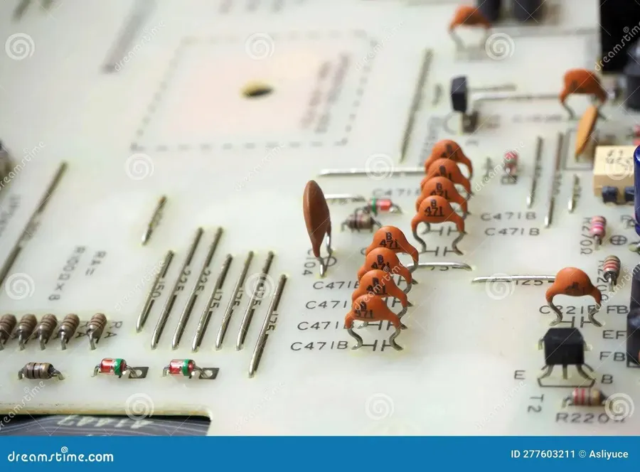
Decoupling capacitors are essential passive electronic components strategically placed in circuits to stabilize the power supply, specifically targeting the reduction of high-frequency noise and voltage fluctuations that can compromise the performance and reliability of electronic devices. Unlike general purpose capacitors, decoupling capacitors are intended to act as a local energy storage reservoir, placed near active components. This ensures that the components have immediate access to a stable power supply, minimizing the impact of voltage spikes and dips that might otherwise occur due to changing current demands within the system.
Fundamentally, a capacitor's ability to store and release electrical energy is defined by its capacitance (measured in Farads), while its operational limits are dictated by its voltage rating. A key characteristic particularly relevant to decoupling is the Equivalent Series Resistance (ESR), which describes the internal resistance of the capacitor, which affects its effectiveness in high-frequency applications.
To effectively visualize a decoupling capacitor's function, consider it a small local reservoir, placed next to an IC, that provides a reliable power source. When the IC draws a surge of current, the capacitor instantly provides the needed charge, preventing dips in the local power supply. Conversely, when the IC’s demand decreases, the capacitor absorbs and stores the surplus energy, mitigating spikes in the supply voltage.
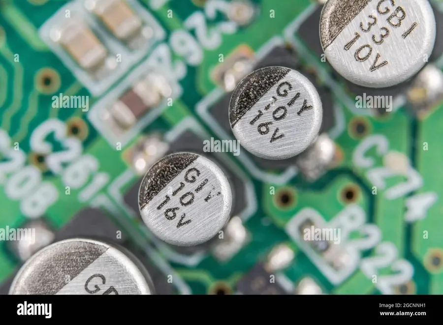
Decoupling capacitors are fundamental components in electronic circuits, primarily acting as localized energy reservoirs to mitigate high-frequency noise and voltage transients, thereby ensuring a stable and reliable power supply. This functionality is crucial for maintaining the integrity of digital signals and preventing erratic circuit behavior.
These capacitors work by providing a low-impedance path for high-frequency alternating current (AC) noise to ground, effectively bypassing the power supply lines. This behavior is essential for several reasons:
In essence, decoupling capacitors are integral for ensuring that the circuit's power supply is stable and free from transient disturbances, which can lead to unreliable operation or functional failure.
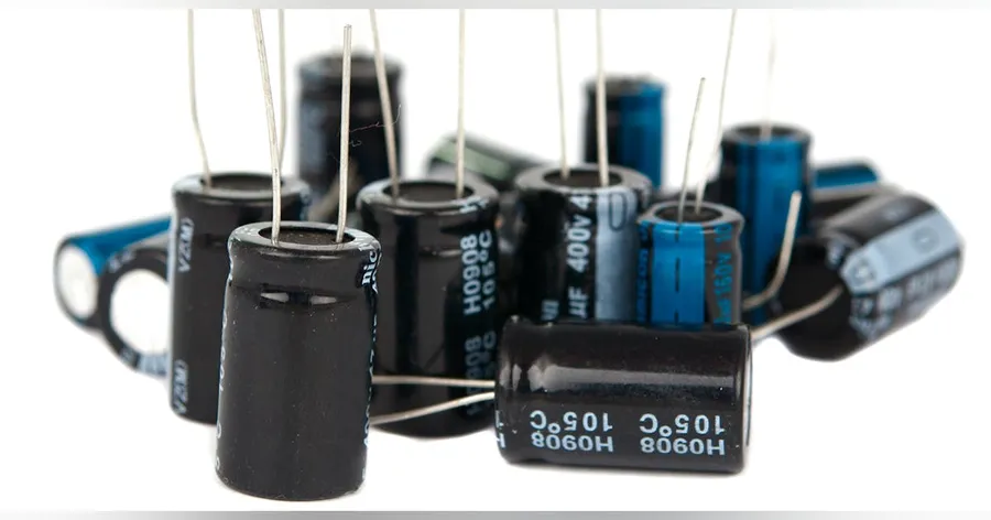
While the terms 'decoupling capacitor' and 'bypass capacitor' are often used interchangeably, subtle differences exist in their application within electronic circuits. Both serve to mitigate noise, yet their primary functions and strategic placements distinguish them.
Decoupling capacitors primarily address noise generated by the integrated circuit itself. Their role is to provide a local reservoir of charge, counteracting rapid fluctuations in the power supply voltage caused by the IC's switching activity. In essence, they 'decouple' the IC from noise present in the main power supply line.
Bypass capacitors, on the other hand, are used to divert high-frequency noise from the power supply line to ground, effectively 'bypassing' the sensitive circuit. These are often placed at the power supply input or at other critical points in the circuit where noise is likely to enter. They provide a low-impedance path for high-frequency currents, preventing them from reaching the sensitive components.
| Feature | Decoupling Capacitor | Bypass Capacitor |
|---|---|---|
| Primary Function | Reduces local noise generated by IC switching | Diverts high-frequency noise from the power supply |
| Placement | Close to the power pins of the IC | Near the power supply input or noise entry points |
| Noise Source | Noise generated by the IC itself | Noise from external sources and the power supply |
| Impedance Role | Provides low impedance path for local high frequency currents | Provides low impedance path for noise to ground |
A practical example can further illustrate their differences. Consider a digital logic circuit. A decoupling capacitor will be positioned very close to the power pins of each integrated circuit, reducing noise generated by switching transistors. A bypass capacitor, on the other hand, might be found at the point where the power supply enters the printed circuit board, mitigating noise originating from the external power supply or associated cables.
In summary, although both decoupling and bypass capacitors are crucial for noise reduction, decoupling addresses locally-generated noise at the component level, while bypass capacitors mitigate externally-sourced noise or power rail noise. Both types of capacitors are essential to achieving stable and reliable circuit performance.
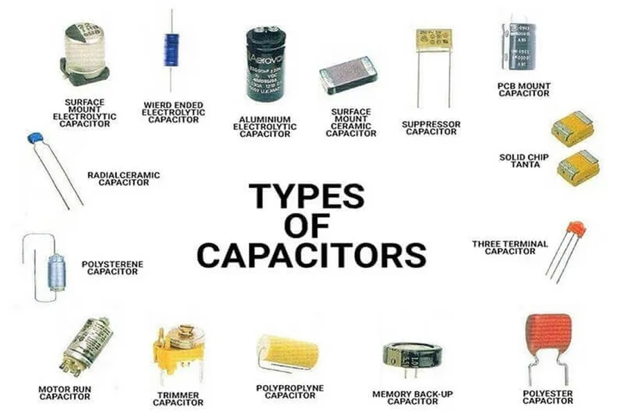
Selecting the appropriate decoupling capacitor is crucial for ensuring stable and reliable circuit performance. This process involves considering several key electrical characteristics and physical properties of the capacitor, each influencing the capacitor's effectiveness in mitigating noise and voltage fluctuations.
| Parameter | Description | Relevance to Decoupling |
|---|---|---|
| Capacitance | The ability to store an electrical charge, measured in Farads (F). | Higher capacitance provides better low-frequency noise suppression. A sufficient capacitance value is required to provide charge to the IC during transient current demands. |
| Voltage Rating | The maximum voltage that the capacitor can safely withstand, usually a DC voltage. | The operating voltage of the circuit must be well within the voltage rating of the capacitor. Failure to do so can cause capacitor failure and potential circuit damage. |
| Equivalent Series Resistance (ESR) | The internal resistance of the capacitor, measured in ohms (Ω). | Lower ESR is crucial for effective high-frequency noise suppression. It allows the capacitor to respond quickly to changes in voltage. |
| Frequency Response | The capacitor's performance in relation to frequency. | Decoupling capacitors should perform well over the frequency range of concern, including the operational frequencies of the IC, as well as any noise frequencies. |
| Capacitor Type | The material and construction of the capacitor. | Different types of capacitors (ceramic, tantalum, electrolytic) have different characteristics in terms of frequency response, ESR, size, and temperature stability, influencing the suitability for specific applications. |
| Package Size | The physical dimensions and form factor of the capacitor. | Physical size and shape determine suitability for PCB placement. Smaller package sizes can facilitate the positioning of capacitors closer to the IC. |
| Temperature Coefficient | Change in capacitance value as a function of temperature. | Capacitor capacitance values change with temperature, depending on the dielectric material. Temperature stability is essential for robust performance, especially in varying conditions. |
The selection of the correct decoupling capacitor type requires careful consideration of the application. Ceramic capacitors are generally preferred for high frequency decoupling due to their low ESR and excellent frequency response. Tantalum capacitors offer higher capacitance values in a small package but may have higher ESR, which can be a problem in some decoupling situations. Electrolytic capacitors have very high capacitance values but also high ESR and are generally unsuitable for decoupling. For optimal decoupling in complex circuits, a combination of capacitor types might be considered to provide a wide frequency response.
Online calculators and simulation tools can aid in the selection process, providing approximate values and simulating performance of specific capacitor types. These tools take into account application parameters and requirements to suggest optimal values for decoupling capacitors. It is important to note that these tools provide starting values, and testing of the capacitor in the final circuit is still needed.
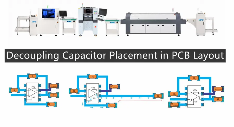
The effectiveness of a decoupling capacitor is not solely determined by its electrical characteristics but also by its physical placement on a Printed Circuit Board (PCB). Strategic positioning is critical to minimize parasitic inductance and resistance, ensuring the capacitor can effectively mitigate noise and voltage fluctuations at the integrated circuit (IC) it is intended to protect.
Decoupling capacitors should be positioned as close as physically possible to the power pin of the IC they are decoupling. This proximity minimizes the parasitic inductance associated with the traces connecting the capacitor to the IC. Parasitic inductance impedes the high-frequency performance of the capacitor, diminishing its ability to effectively filter out noise.
When placing decoupling capacitors in power supply designs, consider that the capacitor should be as close to the load as possible. For multi-layer PCBs, it is generally recommended to place the decoupling capacitors on the same layer as the integrated circuit. This minimizes the need for vias, which add unwanted inductance. When vias are necessary, use multiple vias in parallel to lower the overall inductance.
The length and width of the traces connecting the capacitor and the IC are crucial to capacitor effectiveness. Shorter and wider traces minimize impedance. Avoid using long, thin traces, as these act as inductors and degrade the decoupling performance. PCB design software tools provide features to analyze and simulate the effect of trace length and width, allowing optimal capacitor placement.
PCB layout tools offer features such as parasitic extraction that provide accurate measurements of trace inductance and resistance allowing engineers to understand the performance and refine the placement of decoupling capacitors in a design. Some tools even offer simulations and rules checking for decoupling placement. This functionality can be used to optimize decoupling capacitor performance prior to fabrication. Furthermore, design rule checking ensures compliance with industry standards and best practices.
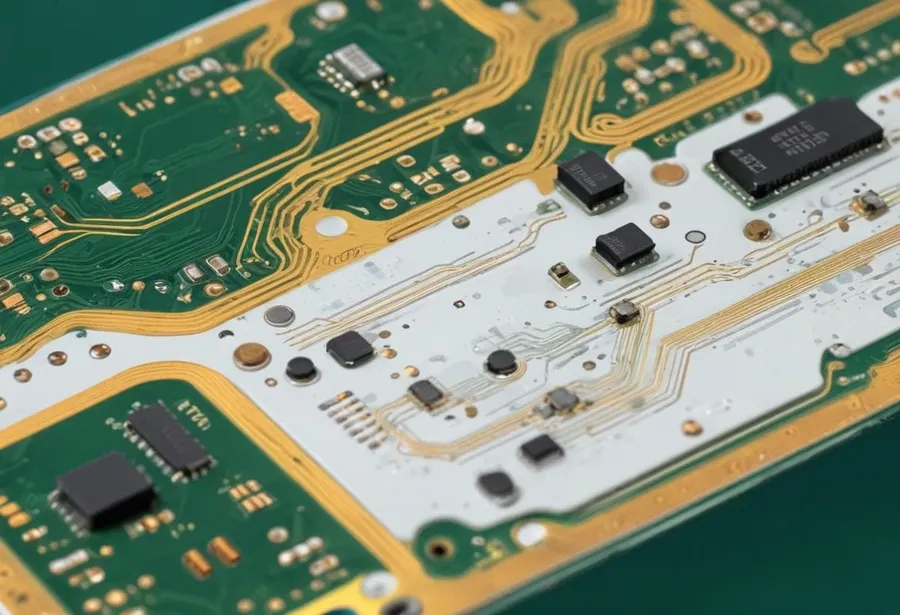
In high-performance systems, basic decoupling techniques may prove insufficient to mitigate noise effectively. Advanced strategies employing multilayer PCBs, multiple capacitors, and ferrites become crucial to ensure signal integrity and power stability.
The demand for cleaner power delivery and minimal signal distortion requires a more nuanced approach to decoupling capacitor implementation. This section delves into these sophisticated methods.
This section addresses common queries regarding decoupling capacitors, providing concise, authoritative answers to improve your understanding and application of these critical circuit components.
Effective decoupling is crucial for stable circuit operation, yet issues can arise. Recognizing these problems and implementing correct solutions is essential for mitigating noise and maintaining signal integrity. This section outlines typical decoupling challenges and provides a methodical approach to resolving them.
A poorly decoupled circuit often manifests through several symptoms: unexpected IC behavior, signal corruption, excessive noise in measurements, and even system instability. These issues are frequently due to insufficient capacitance, incorrect capacitor placement, or impedance mismatches within the power distribution network.
To effectively troubleshoot decoupling issues, a methodical approach is essential. A good start is to verify the circuit diagram against the physical implementation on the PCB. Then, inspect your PCB for proper capacitor placement and look for any signs of capacitor degradation. Finally, use an oscilloscope to measure the noise levels on the power rails and observe for any high frequency oscillations, which can give good hints into decoupling issues.
| Issue | Possible Cause | Solution |
|---|---|---|
| Erratic IC Behavior | Insufficient Decoupling Capacitance or Improper Placement | Increase capacitance, relocate capacitors closer to IC pins, and ensure proper grounding |
| Excessive Noise on Power Rails | Impedance Mismatch, High ESR/ESL Capacitors | Use low ESR/ESL capacitors, optimize trace impedance, and consider a multi-layer PCB for better power distribution |
| High-Frequency Oscillations | Insufficient High-Frequency Decoupling or Poor PCB Design | Add smaller value capacitors for high-frequency decoupling, use ferrites, improve PCB layer stack-up to reduce parasitic inductance |
| Signal Corruption | Poor Decoupling Leading to Noise Injection | Improve decoupling strategy for the IC, use differential signaling, and consider optical isolation where applicable |
| Capacitor Degradation | Capacitor has degraded due to age and/or excessive operation | Replace the capacitor with a new capacitor with the same specifications |
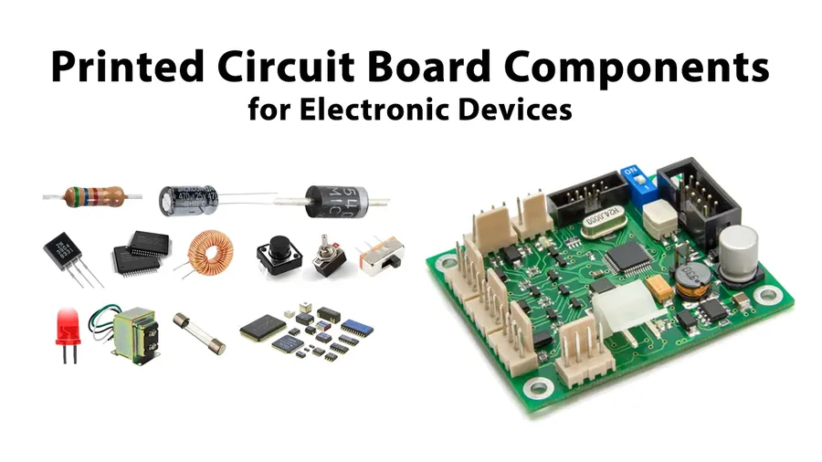
Decoupling capacitors are indispensable components in a vast array of electronic systems, ranging from the simplest circuits to the most complex. Their consistent performance in mitigating noise and ensuring a stable power supply makes them a cornerstone of reliable electronic design. This section explores several practical applications that highlight their importance.
Here are some key applications and the value that decoupling capacitors bring to each.
In summary, decoupling capacitors play a key role in enhancing overall system reliability and performance by ensuring a stable power supply, reducing noise, and maintaining signal integrity across various types of electronic circuits. Their ubiquity across diverse applications highlights their significance in modern electronics design.
Decoupling capacitors are the silent guardians of stable electronics, like a mini power reserve ensuring consistent current. From smoothing voltage ripples to preventing unwanted noise, they're crucial for reliable performance. Understanding how to select the right capacitor and position it strategically on your circuit design can greatly improve the efficiency and robustness of your device. Whether you're a hobbyist or a seasoned engineer, mastering decoupling capacitors is a key step in ensuring your electronic creations operate flawlessly. The future of efficient electronics relies on a fundamental understanding of components like the decoupling capacitor, making them not just a component, but an essential building block of modern electronics.

