
In the volatile, high-stakes world of wind energy, controller electronics are the heartbeat of performance. When a single board failure can cause massive downtime, standard assembly processes aren't enough. We are diving into the specialized DFM strategies that transform industrial electronics into mission-critical, weather-proof solutions.
Understanding the Renewable Energy DFM Landscape

The Challenge of Harsh Operational Environments
Wind turbine control PCBs operate at the edge of industrial performance envelopes. Unlike standard consumer electronics, these assemblies must function reliably for 20+ years while subjected to high-altitude atmospheric pressure changes, extreme temperature swings (often ranging from -40°C to +85°C), and continuous low-frequency mechanical vibrations. A failure in the turbine control system does not just disrupt operation; it risks catastrophic structural damage and incurs immense maintenance costs due to the remote nature of the infrastructure.
Environmental Stress Factors vs. Standard Industry Practices
| Stress Factor | Consumer Standard | Wind Energy DFM Requirement |
|---|---|---|
| Vibration | Minimal | Extended-life mounting & underfill |
| Temperature | Stable/Indoor | Thermal cycling resistant materials |
| Reliability Life | 3–5 years | 20+ years mission-critical |
| Contamination | None/Dust-free | Conformal coating & hermetic sealing |
Key DFM Considerations for High-Reliability Assemblies
- How does thermal management influence PCB layout?
DFM for high-reliability boards requires optimized copper pours and thermal vias that account for differential thermal expansion between substrates and heavy-duty components to prevent solder joint fatigue. - Why is component selection critical?
Engineers must prioritize components with industrial or automotive-grade temperature ratings and avoid parts with high obsolescence risks, ensuring the supply chain supports a multi-decade operational lifespan. - What role does surface finish play in longevity?
Standard HASL finishes are often insufficient; high-reliability designs prioritize ENIG or ENEPIG to provide better co-planarity, solderability, and resistance to electrochemical migration in humid or salty turbine environments.
By shifting from a cost-optimized manufacturing mindset to a reliability-optimized DFM framework, designers can mitigate the inherent risks posed by the unpredictable wind energy landscape. This proactive strategy focuses on minimizing mechanical stress points and enhancing protective measures, ensuring the longevity of critical control logic under the most demanding field conditions.
Substrate Selection for Thermal and Mechanical Stability
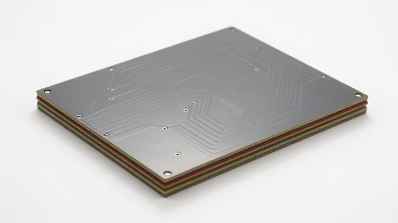
In wind turbine control systems, PCB substrates must withstand continuous thermal cycling and high-frequency vibrations. Standard FR-4 laminates often fail under these conditions due to delamination, pad lifting, or coefficient of thermal expansion (CTE) mismatch. For high-reliability applications, designers must transition to high-Tg (Glass Transition Temperature) materials or Metal Core Printed Circuit Boards (MCPCBs) to ensure long-term system stability.
Comparative Analysis of Substrate Materials
| Substrate Type | Tg (°C) | Thermal Conductivity | Best Use Case |
|---|---|---|---|
| Standard FR-4 | 130-140 | Low | Low-power control logic |
| High-Tg FR-4 | 170-180 | Low | Standard turbine control logic |
| Metal Core (MCPCB) | 170+ | High | Power conversion/Actuators |
| Ceramic/IMS | 250+ | Very High | Harsh high-heat environments |
Mechanical and Thermal Design Considerations
When specifying substrates, the CTE of the material must be closely matched to the components being used, particularly for large BGA packages that are sensitive to solder joint fatigue. High-Tg materials offer superior structural rigidity at operating temperatures, reducing the risk of board warping during sudden thermal shifts. Furthermore, for high-power switching applications, MCPCBs provide an integrated heat sinking path, drastically reducing the thermal resistance between the component and the chassis.
Frequently Asked Questions
- Why is Tg critical in turbine environments?
The Tg indicates when a resin transforms from a rigid state to a rubbery one; exceeding this causes rapid degradation and loss of mechanical support for solder joints. - When should I choose an MCPCB?
Specify an MCPCB when power density exceeds the dissipation capacity of standard FR-4, or when the assembly acts as the primary heat sink for power transistors. - Do I need special fabrication rules for high-Tg materials?
Yes, high-Tg materials often require higher drilling temperatures, specific lamination cycles, and optimized plating processes to ensure reliable via-barrel integrity.
High-Current Trace Routing: Minimizing Heat and Noise
Calculating Trace Capacity and Copper Weight
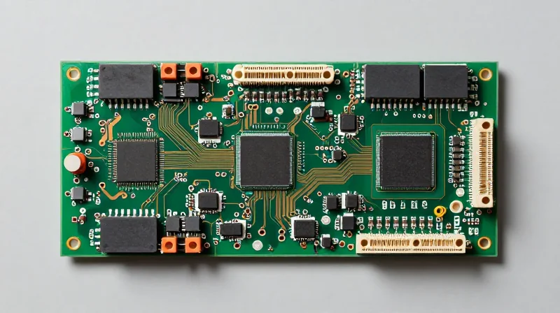
For wind turbine control units, trace sizing must go beyond standard ambient conditions. Engineers must apply the IPC-2152 standard to calculate conductor width based on permissible temperature rise, accounting for the inherent thermal stress of turbine enclosures. Higher copper weights, typically ranging from 2oz to 4oz, are recommended to maintain low impedance and minimize I²R power dissipation.
| Copper Weight | Recommended Application | Thermal Advantage |
|---|---|---|
| 1 oz (35µm) | Control/Signal paths | Low |
| 2 oz (70µm) | Low-voltage power rails | Moderate |
| 4 oz+ (140µm+) | Main Power Inverters/Bus | High |
Mitigating Noise and Inductive Coupling
High-current paths generate significant electromagnetic fields that can corrupt sensitive sensor feedback loops in turbine control. Designers should implement 'Kelvin sensing' for critical current monitoring and ensure power traces are routed with strict return-path control. Separating high-power switching nodes from low-level analog logic using dedicated ground planes is essential for maintaining signal integrity.
DFM Best Practices FAQ
- How does vibration affect high-current trace routing?
Vibration can cause fatigue in heavy components; ensure wide traces are supported by thermal relief pads and consider strain-relieving solder fillets at connection points to prevent cracked joints. - Why avoid right-angle traces in high-current paths?
Right-angle bends can cause impedance discontinuities and trap etching chemicals during manufacturing, potentially creating localized hot spots and structural weaknesses. - What is the role of thermal vias in high-current routing?
Thermal vias act as heat sinks to transfer energy from the trace to internal planes or the PCB underside, effectively increasing the current-carrying capacity by reducing the local junction temperature.
Thermal Management Through Component Placement
In the high-vibration and extreme temperature environment of a wind turbine nacelle, thermal management is not merely about cooling; it is about preventing localized hotspots that accelerate fatigue and material degradation. Effective component placement focuses on creating thermal zones that isolate high-wattage power electronics from sensitive control logic, ensuring uniform heat dissipation across the assembly.
Strategic Heat Source Isolation
To prevent thermal coupling, engineers must adopt a zonated layout strategy. High-power components, such as MOSFETs, IGBTs, and power resistors, should be clustered together at the board perimeter near heat sink interfaces. Conversely, signal-sensitive components—such as microcontrollers, ADCs, and precision references—should be positioned at the opposite end of the PCB, separated by thermal moats or isolation slots to prevent cross-talk induced by thermal expansion.
| Component Type | Placement Rule | Thermal Priority |
|---|---|---|
| Power MOSFETs/IGBTs | Near board edge / Heat sink | High (Requires low thermal resistance) |
| Precision Sensors | Isolated from power plane | Medium (Requires stability) |
| Electrolytic Capacitors | Away from heat sources | High (Critical failure point) |
Optimizing Thermal Relief for Solder Reliability
Thermal relief patterns are essential during assembly to ensure consistent solder joint quality. Without proper relief, high-copper-pour areas act as heat sinks during reflow, leading to cold solder joints or tombstoning. For high-reliability turbine applications, we recommend a cross-hatched or spoke-based thermal relief pattern for all pads connected to internal planes, allowing for enough electrical connectivity while preventing excessive heat transfer.
- Why must capacitors be kept away from high-heat zones?
Electrolytic capacitors are highly sensitive to temperature; constant exposure to radiant heat from power components significantly reduces their electrolyte lifespan and increases ESR. - How does thermal relief impact mechanical longevity?
Thermal relief reduces the mechanical stress on solder joints by allowing localized flexibility, which is vital in wind turbines where the PCB undergoes constant vibration and thermal cycling. - When should thermal vias be used?
Thermal vias should be used under high-power surface-mount pads to conduct heat into internal ground planes, provided they are properly filled and capped to prevent solder wicking.
Advanced Conformal Coating Techniques for Harsh Environments
For wind turbine control assemblies operating in remote or offshore environments, standard conformal coating is insufficient. Reliability depends on selecting chemistries that provide robust dielectric strength and chemical resistance while accommodating the differential thermal expansion coefficients of the underlying substrate and components.
Selecting Coating Chemistries for Harsh Climates
| Coating Type | Key Advantage | Environment Suitability |
|---|---|---|
| Parylene | Uniform Pin-hole free | Extreme moisture/Salt |
| Silicone | Thermal flexibility | High thermal cycling |
| Urethane | Abrasion resistance | General industrial |
DFM Considerations for Coating Application
Successful coating implementation requires proactive DFM measures to ensure full coverage and prevent migration into non-coated areas such as high-current connectors.
- Connector Masking
Design keep-out zones around sensitive connectors to eliminate the need for manual masking, which is prone to human error and potential contamination. - Component Clearance
Ensure a minimum clearance of 0.5mm between components to allow fluid capillary action for edge coverage, preventing localized coating thinness. - Surface Preparation
Specify automated ion chromatography cleaning processes to remove ionic contaminants before application, which prevents dendritic growth beneath the coating layer.
Advanced Application Techniques
To achieve maximum reliability in turbine control, selective robotic dispensing is preferred over dip or spray methods. Robotic systems provide precise volume control and thickness consistency, which is critical for maintaining consistent signal integrity on high-frequency communication lines within the controller.
Solder Joint Integrity and Mechanical Stress Mitigation
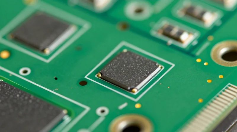
Wind turbine control systems operate in environments defined by constant mechanical oscillation and structural resonance. For PCBs, these vibrations translate directly into dynamic stress at solder joint interfaces. To prevent fatigue cracking and intermetallic layer embrittlement, designers must prioritize mechanical reinforcement and stress-distributing layout patterns.
Strategic Component Anchoring and Mechanical Support
Surface Mount Technology (SMT) components, particularly large connectors and heavy electrolytic capacitors, are highly susceptible to vibrational failure. Implementing localized reinforcement strategies is essential to offload mechanical stress from the solder fillets.
- Corner Staking and Underfilling
Apply high-modulus, low-outgassing epoxy to the corners of BGA packages or underneath large surface-mount components. This creates a mechanical bridge that redistributes stress away from solder balls. - Through-Hole Retention
For high-mass components, utilize PTH (Plated Through-Hole) designs with mechanical clips or press-fit pins to ensure that the board substrate, rather than the solder joint, bears the inertial load. - Rigid Support Frames
Incorporate board-stiffening rails or mid-board standoffs to increase the natural frequency of the PCB assembly, keeping it well above the dominant vibrational frequencies produced by the turbine gearbox and blades.
Solder Joint Geometry and Material Selection
| Feature | Standard Design | High-Reliability DFM Rule |
|---|---|---|
| Pad Geometry | Symmetric/Round | Teardropping/Filleted traces |
| Solder Alloy | SAC305 | Innolot or high-ductility alloys |
| Copper Weight | 1 oz | 2 oz+ for increased pad anchorage |
The choice of solder alloy is a primary factor in survivability. While standard SAC305 is sufficient for consumer electronics, turbine controllers should transition to specialized 'high-reliability' alloys. These materials contain trace additives that improve ductility and minimize grain coarsening during prolonged thermal and mechanical cycling.
Frequently Asked Questions on Mechanical Reliability
- How does PCB thickness influence vibration performance?
A thicker, more rigid board (e.g., 2.4mm instead of 1.6mm) reduces flexure during vibration, decreasing the strain energy absorbed by solder joints. - Why is teardropping critical for high-vibration PCBs?
Teardropping increases the copper contact area between the pad and the trace, which eliminates the stress concentration point where common fatigue cracks typically originate.
Compliance and Quality Control Protocols
Adherence to IPC Standards for High-Reliability Assemblies
For wind turbine control systems, compliance with IPC-A-610 Class 3 is non-negotiable. This classification, designated for 'High-Performance Electronic Products,' demands that PCB assemblies maintain continuous functionality even under extreme environmental exposure and mechanical vibration. Ensuring compliance requires rigorous validation of solder fillet geometries, component orientation, and surface finish integrity throughout the PCBA process.
Quality Control Matrix for Turbine Reliability
| Protocol | Standard | Primary Objective |
|---|---|---|
| Acceptability | IPC-A-610 Class 3 | Ensuring mission-critical reliability |
| Design Rules | IPC-2221/2222 | Optimizing layout for high-stress zones |
| Coating Integrity | IPC-CC-830 | Preventing ionic contamination and salt corrosion |
| Solder Performance | J-STD-001 | Guaranteeing structural integrity under vibration |
In-Process Quality Assurance (IPQA) Measures
Beyond certification, high-reliability PCBs necessitate proactive IPQA. Automated Optical Inspection (AOI) must be supplemented by X-ray inspection for hidden solder joints on BGA and QFN packages, common in modern turbine controllers. Furthermore, environmental stress screening (ESS) should be integrated to simulate field temperature fluctuations and mechanical shock before final deployment.
- What is the primary role of ionic contamination testing?
It verifies that flux residues and manufacturing contaminants have been removed to prevent dendrite growth and short circuits in high-humidity turbine environments. - Why is traceability essential in this sector?
Detailed component-level traceability allows for rapid root-cause analysis in the event of field failure, ensuring safety recalls can be targeted and efficient. - How do we validate thermal design efficacy?
Thermal imaging and thermocouple monitoring under load during the prototype phase validate that component temperatures stay well within derating limits.
Testing for Mission-Critical Reliability

Implementing Rigorous Environmental Stress Screening (ESS)
In the high-stakes environment of wind energy, reliability testing must extend beyond basic functional verification. Environmental Stress Screening (ESS) serves as the primary mechanism for identifying latent manufacturing defects that could lead to premature field failure. By subjecting PCBs to controlled, accelerated stressors, engineers can precipitate 'infant mortality' failures in a factory setting rather than at the turbine site.
| Test Type | Primary Stressor | Failure Mechanism Detected |
|---|---|---|
| Thermal Cycling | Rapid temperature shifts | Solder joint fatigue and delamination |
| Random Vibration | Broadband frequency excitation | Loose components and trace fractures |
| Highly Accelerated Life Testing (HALT) | Combined thermal and mechanical | Design margin limitations and marginal solder bonds |
Optimizing Burn-in and Reliability Validation
Burn-in testing validates that the DFM strategy effectively accounts for component derating and power distribution integrity. By running the PCB at maximum load while elevated at extreme ambient temperatures, manufacturers can ensure that thermal management strategies are sufficient and that sensitive components remain within their operational safety envelopes.
- How does burn-in duration influence reliability outcomes?
Duration is typically determined by the bathtub curve of the specific components used. A period of 24 to 48 hours is standard to ensure the board has passed through the initial infant mortality phase without degrading the service life of healthy components. - Why is power-on testing during thermal cycling crucial?
Static testing often misses intermittency issues. Monitoring power supply stability and signal integrity under dynamic load during thermal transitions reveals poor solder connections or marginal vias that only exhibit failure when mechanical expansion occurs. - How should test data be integrated back into the DFM cycle?
Data logs from testing phases must be analyzed statistically. If specific components show high failure rates, the DFM rules regarding placement, heat sinking, or solder paste volume must be updated to prevent recurrence in future design iterations.
Mastering DFM in renewable energy assembly is the difference between a prototype and a resilient, long-term asset. By prioritizing thermal management, trace integrity, and environmental shielding, your project can withstand the most grueling field conditions. Are you ready to optimize your next turbine control design? Contact our engineering team today for a comprehensive DFM audit.
