
In the demanding world of industrial HVAC, downtime is not just an inconvenience—it is a financial and operational failure. Engineers tasked with designing control boards must navigate extreme thermal cycles, vibration, and signal noise. This deep dive provides a blueprint for mastering Design for Manufacturing (DFM) to bridge the gap between initial concept and zero-defect production.
The Critical Role of DFM in Industrial HVAC Applications
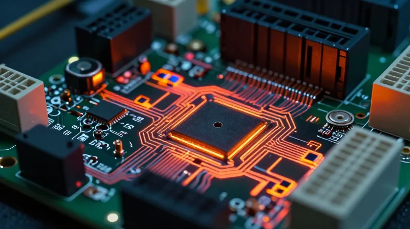
The Necessity of DFM in Harsh Environments
Industrial HVAC systems often operate in environments characterized by extreme temperature fluctuations, high humidity, and persistent vibrations. Unlike consumer electronics, these units require a design philosophy that prioritizes physical durability and assembly consistency from the start. Implementing DFM best practices allows engineers to mitigate common failure points like solder joint fatigue, trace delamination, and component stress long before a single board enters the production line.
DFM Constraints for Industrial Reliability
| Design Factor | HVAC Requirement | DFM Action |
|---|---|---|
| Thermal Management | High thermal cycling | Optimize via spacing and thermal vias |
| Vibration Resistance | Mechanical stress | Implement underfill and staking |
| Moisture Protection | Condensation risk | Clearance for conformal coating |
Key Questions in Industrial HVAC PCB Design
- How does DFM affect long-term field reliability?
By enforcing strict manufacturing guidelines, DFM reduces assembly defects that manifest as failures under environmental stress, significantly extending the MTBF (Mean Time Between Failures) in harsh climates. - Why is component placement critical for HVAC systems?
Proper placement prevents thermal bottlenecks, ensures consistent solder paste coverage, and allows for effective inspection, all of which are essential for units subjected to constant mechanical vibration.
Ultimately, DFM is not merely about cost-cutting; it is about risk management. By integrating manufacturability checks into the PCB design phase, engineers ensure the control unit can withstand years of industrial use without compromise.
Material Selection for High-Temperature Durability
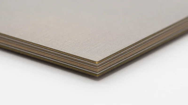
In industrial HVAC control units, PCBs are frequently subjected to extreme temperature fluctuations that accelerate mechanical stress. Utilizing standard FR-4 materials often leads to dielectric breakdown, trace peeling, and solder joint fractures. Engineers must prioritize substrates with high glass transition temperatures (Tg) and low coefficient of thermal expansion (CTE) values to maintain structural stability across the operating lifespan.
Selecting the Right PCB Substrate
The primary objective is to select a laminate that remains rigid and stable throughout the device's thermal range. A high-Tg material (typically >170°C) is mandatory to prevent the resin from softening, which can cause excessive Z-axis expansion and subsequent through-hole plating failure.
| Material Property | Standard FR-4 | High-Tg / Ceramic-Filled |
|---|---|---|
| Glass Transition Temp (Tg) | ~130-140°C | 170°C - 200°C+ |
| Thermal Reliability | Low (prone to delamination) | High (excellent stability) |
| CTE Performance | High mismatch risk | Optimized for copper matching |
Thermal Interface Material (TIM) Integration
Beyond the substrate, how you dissipate heat from high-power components like MOSFETs and microcontrollers defines the robustness of your control unit. High-performance TIMs ensure that thermal impedance remains low, preventing localized overheating that leads to board warping.
- Why is Z-axis CTE critical?
During thermal expansion, the PCB material expands faster than the copper barrels in vias. A low Z-axis CTE minimizes this tension, preventing microscopic cracks in the plating. - What should be avoided?
Avoid standard, low-cost FR-4 for outdoor or industrial units with high current density, as these materials lack the cross-linking density required to withstand sustained cyclic thermal loads. - How does filler content impact durability?
Ceramic-filled resins improve thermal conductivity and reduce CTE, creating a more cohesive structure that resists cracking under extreme environmental stress.
Optimizing PCB Layouts for Thermal Dissipation
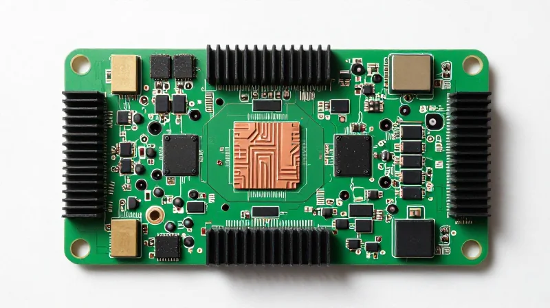
Strategic Component Placement for Thermal Load Balancing
Thermal management begins by isolating heat-generating power electronics from sensitive control logic. High-current MOSFETs, inductors, and gate drivers should be clustered in a dedicated power stage, away from high-impedance analog inputs and communication microcontrollers. By establishing these 'thermal zones,' designers can prevent localized hotspots from compromising signal integrity or accelerating the aging of critical low-power components.
Optimizing Thermal Vias and Copper Pours
Thermal vias serve as the primary conduit for moving heat from surface-mount component pads into internal ground planes. To maximize efficiency, vias must be placed in a tight grid pattern directly under the thermal pad of high-current devices. Stitching these to large, unmasked copper pours on the board's exterior acts as a radiator, significantly increasing the convective surface area.
| Technique | Primary Benefit | Implementation Rule |
|---|---|---|
| Copper Pouring | Increased Thermal Mass | Maintain at least 1oz to 2oz thickness |
| Thermal Vias | Improved Vertical Heat Path | Plated-through, filled, and capped (VIPPO) |
| Component Spacing | Reduced Heat Concentration | Minimum 5mm between high-power packages |
Frequently Asked Questions on Thermal DFM
- Should I use solder-filled thermal vias?
Yes, filling and capping vias (VIPPO) is highly recommended for high-current HVAC controllers to prevent solder wicking and ensure a solid, reliable thermal bridge to internal layers. - Does copper weight impact thermal performance?
Significantly. Increasing copper weight from 1oz to 2oz effectively halves the thermal resistance of your ground planes, allowing for superior heat spreading across the entire PCB assembly. - Where should the hottest components be placed?
Position high-dissipation components toward the board edge or near airflow paths if active cooling is present, ensuring that heat is directed away from the center of the PCB.
Ensuring Signal Integrity Under Electromagnetic Interference

Mastering Signal Integrity and Noise Isolation
HVAC systems frequently integrate high-power switching components like compressors and blower motors alongside sensitive low-voltage microcontrollers. To maintain signal integrity, designers must strictly enforce the separation of analog and digital ground planes, employ differential signaling for critical data lines, and implement effective decoupling strategies at the point of load.
Comparing Signal Integrity Strategies
| Strategy | Primary Benefit | Implementation Priority |
|---|---|---|
| Differential Pairs | Common-mode noise rejection | High (for sensors/comm) |
| Stitched Ground Vias | Reduced loop inductance | High (full board) |
| Ferrite Beads | High-frequency suppression | Medium (power entry) |
Frequently Asked Questions
- How do I effectively isolate switching noise from analog sensors?
Utilize a star-ground configuration to prevent return currents from high-current switching loops from polluting the analog reference plane. Additionally, ensure physical distance or separate board zones for noisy power stages. - Is physical shielding necessary for every HVAC controller?
Shielding is essential when operating near high-power inductive loads like HVAC motors; localized metallic shields over sensitive micro-controllers and oscillators can significantly lower radiated emissions and susceptibility. - What role does trace impedance control play in HVAC reliability?
Proper impedance control minimizes signal reflections and ringing, which are common catalysts for intermittent digital logic errors and communication failures in long cable runs common in industrial HVAC systems.
Advanced Solder Joint Design and Reliability

Geometric Optimization for Stress Mitigation
In HVAC control units, solder joints are the primary mechanical anchors for components. Standard IPC guidelines serve as a baseline, but industrial environments necessitate tighter control over pad geometry. To minimize localized stress, utilize non-solder mask defined (NSMD) pads for BGAs and QFNs, as they offer better mechanical interlocking and allow for higher solder fillet volumes. For leadless components, extending pads slightly beyond the package perimeter improves fillet inspection and increases surface area, thereby enhancing mechanical endurance against vibrational fatigue.
Stencil Design and Paste Management
The consistency of the solder paste deposit is critical for creating joints capable of enduring industrial loads. Stencil apertures should be laser-cut with electro-polished walls to ensure smooth paste release and consistent volume. For fine-pitch components prone to stress fractures, consider a reduction ratio of 10% on aperture size relative to the pad to prevent excess solder and potential bridging while maintaining required volume.
| Parameter | HVAC Application Requirement | DFF Recommendation |
|---|---|---|
| Solder Alloy | High thermal cycling | SAC305 or high-reliability alloys |
| Paste Type | Vibration resistance | Type 4 or 5 mesh for consistency |
| Aperture Design | Stress reduction | Rounded corners to reduce stress risers |
Frequently Asked Questions
- Why is SAC305 often preferred over traditional SnPb for HVAC units?
While SAC305 is lead-free, its robust mechanical strength and performance under harsh thermal conditions make it ideal for the vibration-heavy environment of HVAC blower and compressor control. - Does corner radius on pads influence reliability?
Yes, pads with rounded corners significantly reduce the concentration of mechanical stress at the solder fillet interface, which is a common failure point during long-term vibration exposure. - How does stencil thickness affect joint fatigue?
Excessively thin stencils result in insufficient volume, leading to weak joints that fail early. Always balance the stencil thickness with the required standoff height for high-mass components.
DFM Verification: The Design Rule Check (DRC) Checklist
For industrial HVAC control units, the Design Rule Check (DRC) is not merely a final validation step but a continuous engineering discipline. By embedding DFM constraints directly into the CAD environment, designers can identify potential fabrication conflicts—such as insufficient annular rings, solder bridging risks, or drill-to-copper clearances—well before files reach the assembly house.
Critical DFM Verification Checklist
| Category | Verification Metric | HVAC Impact |
|---|---|---|
| Copper Features | Trace Width/Spacing | Prevents shorting in high-current switching paths. |
| Drill Parameters | Annular Ring Size | Ensures connectivity during high-vibration operation. |
| Solder Mask | Mask Clearance/Registration | Prevents solder bridges near compact high-density logic. |
| Silk Screen | Component Reference Overlap | Ensures clarity for manual rework and technician troubleshooting. |
Optimizing DRC for Manufacturing Readiness
To achieve high yield rates for robust HVAC units, the DRC must encompass both electrical and mechanical verification. Automated DRC scripts should be configured to the specific capabilities of your fabrication partner, focusing on the limitations of the PCB stackup and drilling capabilities.
- How does layer stackup symmetry affect HVAC unit reliability?
Symmetric stackups prevent board warpage during the reflow process, which is essential when mounting large, heat-sinked components common in HVAC control units. - Why should I prioritize copper-to-edge clearances in my DRC?
HVAC units are often installed in metal chassis environments; insufficient edge clearance risks shorting the PCB ground plane to the industrial enclosure. - Is manual inspection still required after an automated DRC?
Yes. Automated tools catch geometric violations, but a manual design review is necessary to ensure thermal relief patterns and high-current path widths are optimized for the specific power requirements of the HVAC system.
Streamlining the Transition from Prototype to Mass Production
Bridging the Gap: Production-Ready Design
The gap between a functional prototype and a scalable manufacturing run is often defined by the maturity of the documentation and the standardization of the layout. To minimize cycle times, designs must move beyond basic connectivity to incorporate DFM constraints that accommodate automated assembly line tolerances and specific equipment capabilities of the Contract Manufacturer (CM).
Key Transition Optimization Strategies
- Panelization Efficiency
Early engagement with your CM on panel design is essential. Standardize board dimensions to fit optimized panel arrays to maximize panel utilization and reduce material waste. - Component Standardization
Limit the use of non-standard or 'boutique' components that introduce supply chain risks or require manual assembly intervention, which significantly increases throughput time. - DFM-Aligned Documentation
Provide complete ODB++ or IPC-2581 data packages rather than legacy Gerber files to reduce ambiguity regarding stack-ups, drill layers, and assembly instructions.
Prototyping vs. Production Metrics
| Design Factor | Prototype Focus | Production Focus |
|---|---|---|
| Component Selection | Fastest availability | Cost, longevity, second-source |
| Test Strategy | Manual probing | Automated In-Circuit Test (ICT) |
| Assembly Process | Manual/Quick-turn | Fully automated SMT line |
| Panelization | Single unit | Optimized array |
By integrating ICT (In-Circuit Testing) pads and fiducial markers at the design stage, you ensure that the transition to mass production doesn't require board re-spins to accommodate testing fixtures. Always conduct a final DFM audit with your manufacturing partner specifically focused on machine-level parameters such as pick-and-place alignment capabilities and wave-soldering clearances.
Continuous Improvement Through Failure Analysis

Continuous improvement in industrial HVAC PCB design requires a closed-loop feedback mechanism where field return analysis informs DFM updates. By treating every failure as a data point, engineers can identify subtle vulnerabilities in solder joint integrity, thermal management, or component placement that standard DRCs may overlook.
Turning Failure into Design Intelligence
The transition from reactive troubleshooting to proactive design hardening centers on forensic PCB analysis. When an HVAC unit returns from the field due to environmental stress, the layout team must correlate the physical failure mode—such as fatigue cracking or whisker formation—back to specific design choices.
| Failure Mode | Root Cause Indicator | DFM/Design Adjustment |
|---|---|---|
| Solder Joint Cracking | Excessive thermal cycling | Modify pad geometry/solder mask relief |
| Component Pop-off | High-vibration stress | Add underfill or change orientation |
| Electrochemical Migration | Condensation/Humidity | Adjust conformal coating keep-out zones |
Operationalizing the Feedback Loop
- How should field return data influence future DRCs?
Each recurring failure should result in an automated DRC rule update, ensuring that subsequent board revisions automatically flag vulnerable design patterns for manual review. - What is the role of Root Cause Analysis (RCA) in DFM?
RCA serves as the bridge between manufacturing floor defects and field failures, allowing engineers to adjust component placement or trace routing to accommodate real-world assembly tolerances. - Why is version control critical for continuous improvement?
Detailed hardware revision histories allow for precise correlation between environmental stress test results and physical design modifications, validating the effectiveness of DFM changes.
Ultimately, the robustness of an industrial HVAC control unit is a byproduct of iterative refinement. By embedding failure analysis into the DFM workflow, organizations transform historical field data into a strategic asset that minimizes long-term warranty costs and maximizes equipment uptime.
Achieving industrial-grade reliability requires a rigorous commitment to DFM principles, from material selection to final assembly verification. By prioritizing signal integrity and thermal robustness, your team can drastically reduce field failures and production costs. Ready to optimize your HVAC control board manufacturing process? Contact our engineering team today to discuss your next high-reliability project.
