In the realm of audio technology, the digital sound card stands as a cornerstone for high-fidelity sound reproduction and processing. Whether you're a dedicated audiophile, a professional musician, or a gaming enthusiast, the quality of your audio experience hinges significantly on the underlying PCB (Printed Circuit Board) design and manufacturing. At Zero One Solution Limited, we understand the critical role a well-engineered PCB plays in achieving superior audio performance. With our extensive experience in PCB solutions, we provide comprehensive services from design to manufacturing and assembly, tailored to meet the exacting demands of digital sound card applications. This article delves into the intricacies of digital sound card PCB solutions, exploring the key considerations, challenges, and innovative approaches that ensure optimal audio quality and reliability. Let's explore how Zero One Solution Limited can empower your audio projects with cutting-edge PCB technology.
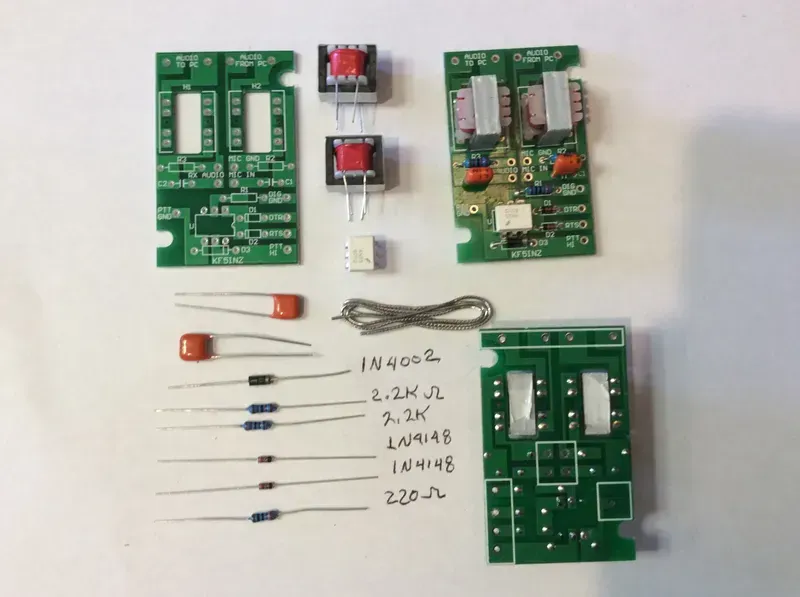
At the core of every high-fidelity audio experience, from professional recording studios to immersive gaming setups, lies the Digital Sound Card. The Printed Circuit Board (PCB) is the foundational element that dictates the sound card's performance, acting as the intricate nervous system that connects and empowers every component. A meticulously engineered PCB is not merely a platform for mounting parts; it is a critical enabler of signal integrity, noise reduction, and ultimately, the pristine audio quality that discerning users demand.
| Component | Function | PCB Impact |
|---|---|---|
| Digital-to-Analog Converter (DAC) | Converts digital audio signals to analog | PCB layout affects signal path purity and noise immunity to the DAC's output. |
| ][ |
Designing a high-performance Digital Sound Card PCB necessitates a meticulous approach to several critical factors that directly influence audio fidelity and system stability. At its core, the goal is to preserve signal integrity, minimize noise, and manage thermal dissipation effectively to ensure uncompromised sound reproduction. This section will delve into the essential design considerations that empower engineers to craft superior audio PCBs, laying the foundation for an exceptional auditory experience.
| Design Consideration | Description | Impact on Audio Performance |
|---|---|---|
| Signal Integrity (SI) | Ensuring accurate and undistorted transmission of analog and digital audio signals by controlling impedance, crosstalk, and reflections. | Crucial for preserving audio waveform accuracy, preventing jitter, and maintaining high-fidelity sound output. |
| Noise Reduction | Implementing techniques to minimize electrical noise (EMI/RFI, power supply noise, ground noise) that can corrupt audio signals. | Directly affects the signal-to-noise ratio (SNR) and dynamic range, leading to clearer sound with less hiss or hum. |
| Thermal Management | Managing heat generated by active components (e.g., amplifiers, DACs) to prevent performance degradation and component damage. | Prevents thermal drift in analog components, maintains stable operating characteristics, and prolongs component lifespan, ensuring consistent audio quality. |
| Grounding Schemes | Designing effective ground planes and star-ground configurations to provide a stable reference and prevent ground loops. | Reduces common-mode noise, improves crosstalk rejection, and is fundamental for achieving a low-noise floor. |
| Component Placement | Strategic positioning of sensitive analog and digital components, power sections, and connectors. | Minimizes signal path lengths, reduces coupling between sensitive circuits, and aids in effective EMI shielding. |
Beyond these foundational elements, the intricate interplay between component selection, trace routing, and power delivery networks dictates the ultimate success of an audio PCB. For instance, using low-ESR capacitors in power filtering, employing differential signaling for sensitive audio paths, and ensuring proper decoupling are all vital steps in mitigating potential issues. Zero One Solution Limited leverages its extensive experience in high-precision PCB manufacturing to meticulously address these design facets, guaranteeing that every digital sound card PCB meets the stringent demands of modern audio applications, ensuring both reliability and unparalleled sound quality.
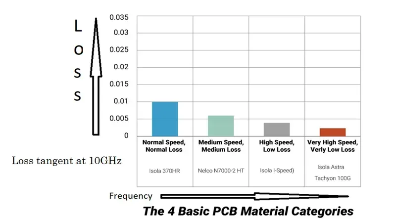
The foundation of a high-fidelity digital sound card PCB lies not only in its design but critically in the selection of appropriate materials. Just as the conductor choice influences current flow, the PCB substrate material, copper foil, and solder mask profoundly impact signal integrity, impedance control, and ultimately, audio reproduction quality by minimizing dielectric loss and ensuring stable electrical characteristics across frequency ranges.
| Material Type | Dielectric Constant (Dk) | Dissipation Factor (Df) | Key Advantage for Audio PCBs | Typical Application |
|---|---|---|---|---|
| FR-4 (Standard) | 4.2-4.7 | 0.015-0.025 | Cost-effective, widely available | General-purpose audio devices |
| High-Tg FR-4 | 4.5-4.8 | 0.015-0.020 | Improved thermal stability, reliable in higher power scenarios | Professional audio equipment, power amplifiers |
| Rogers (PTFE-based) | 2.2-3.5 | 0.0009-0.004 | Extremely low signal loss, excellent high-frequency performance | High-end audio, RF components in sound cards |
| Nelco N4000-13 SI | 3.6-3.8 | 0.008-0.012 | Excellent signal integrity, consistent Dk/Df | High-speed digital audio interfaces, DACs |
| Isola 370HR | 4.0-4.3 | 0.008-0.010 | Good thermal performance, reliable for multi-layer designs | Complex multi-channel audio systems |
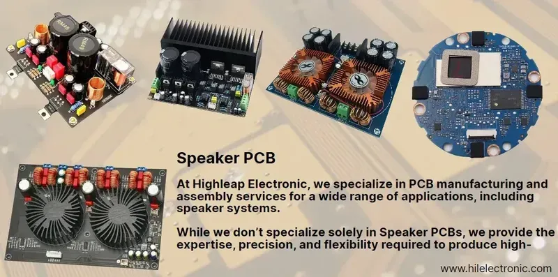
Manufacturing high-quality digital sound card PCBs demands meticulous attention to detail and advanced techniques that directly impact audio fidelity. The precision of manufacturing processes, including strict impedance control, optimized layer stacking, and superior surface finishes, is paramount to achieving the pristine signal integrity essential for exceptional audio performance. These techniques mitigate signal degradation, minimize electromagnetic interference (EMI), and ensure consistent electrical characteristics across the board, making them fundamental to producing a reliable and high-performing digital sound card solution.
| Manufacturing Technique | Description | Impact on Audio Performance |
|---|---|---|
| Impedance Control | Precise management of trace impedance to match component requirements, preventing signal reflections and ensuring efficient power transfer. | Crucial for maintaining signal integrity, minimizing distortion, and ensuring clear, accurate audio reproduction across all frequencies. Without it, high-frequency signals can be severely degraded, leading to a loss of detail and clarity in the audio output. Proper impedance matching ensures that the maximum amount of power is transferred from the source to the load, critical for audio amplifiers and high-speed data lines in DACs (Digital-to-Analog Converters). |
| Layer Stacking (Stack-up) | Strategic arrangement of PCB layers (signal, ground, power planes) to optimize signal routing, reduce crosstalk, and provide effective shielding. | Optimized layer stack-up is vital for reducing noise and EMI, providing robust ground planes for return paths, and minimizing impedance discontinuities. A well-designed stack-up can significantly reduce common-mode noise and improve the signal-to-noise ratio, leading to a cleaner audio output with less background hiss or hum. The isolation of sensitive analog signals from noisy digital signals through proper layer separation is also a key benefit, preventing digital noise from coupling into the analog audio path and ensuring high-fidelity audio reproduction. This contributes to better overall soundstage and clarity by preserving the purity of the audio signal from input to output, as validated by industry standards like IPC-2221B for PCB design and performance guidelines. |
| Surface Finish | Application of a protective coating (e.g., ENIG, OSP) to exposed copper pads to ensure solderability and prevent oxidation. | The surface finish impacts the reliability of solder joints, which directly affects signal integrity over time. A stable and consistent solder joint ensures minimal contact resistance, preserving signal purity and preventing intermittent connections that could introduce noise or signal loss. For high-frequency audio signals, any increase in resistance due to poor surface finish or oxidation can degrade the signal, leading to reduced sound quality. The choice of finish, such as Electroless Nickel Immersion Gold (ENIG), offers excellent flatness and shelf life, which are critical for fine-pitch components and stable electrical connections, as discussed in numerous IPC standards (e.g., IPC-6012 for rigid PCBs) concerning performance and reliability. |
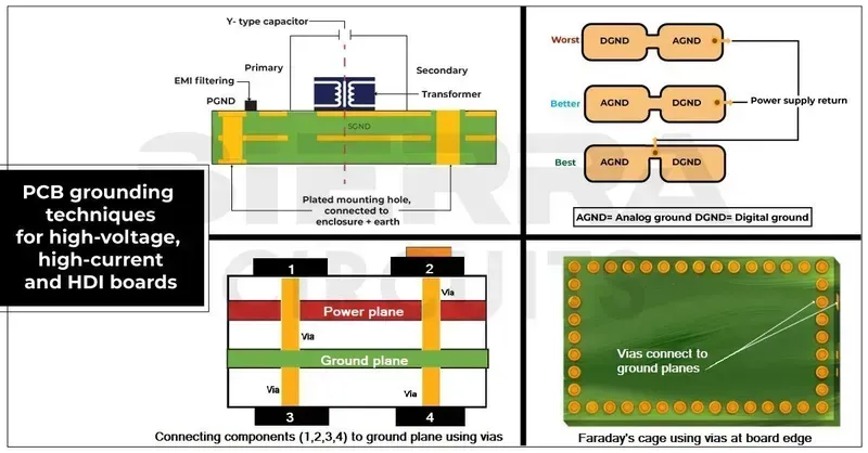
Achieving pristine audio quality in digital sound cards hinges critically on effectively mitigating noise and interference within the PCB design. Unwanted electrical noise, whether from power supplies, adjacent traces, or external electromagnetic fields, can significantly degrade the signal-to-noise ratio, leading to audible distortions, hums, or loss of clarity. A strategic approach to PCB layout, encompassing meticulous grounding, effective shielding, and optimized component placement, is paramount to preserving the integrity of sensitive audio signals and delivering an uncompromised listening experience.
| Noise Type | Common Causes | PCB Mitigation Strategy |
|---|---|---|
| Power Supply Noise | Ripple, voltage fluctuations from power regulators | Proper decoupling capacitors, LDOs, dedicated power planes, ferrite beads |
| Crosstalk | Electromagnetic coupling between adjacent traces | Increased trace spacing, differential routing, guard traces, short trace lengths |
| EMI/RFI | External electromagnetic fields, high-frequency switching | Ground planes, shielding layers, proper component selection (low EMI), Faraday cages |
| Ground Loop Noise | Multiple ground paths creating voltage differences | Star grounding, single-point grounding for analog/digital separation |
In the realm of high-fidelity audio, the seemingly subtle aspect of impedance control on a Printed Circuit Board (PCB) holds profound significance, directly impacting signal integrity and the purity of sound reproduction. Impedance control is not merely a technical detail; it is a critical design discipline that ensures consistent signal propagation characteristics, preventing undesirable reflections and maintaining the intended waveform shape, which is paramount for crystal-clear digital audio signals.
| Aspect of Impedance Control | Impact on Audio Signal Integrity | Relevance for Digital Sound Card PCBs |
|---|---|---|
| Signal Reflections | Mismatched impedance causes signal reflections, leading to signal distortion, ringing, and inter-symbol interference (ISI). This degrades audio clarity and introduces noise. | Crucial for high-speed digital audio data paths (e.g., I2S, S/PDIF) to prevent data corruption and ensure accurate audio reconstruction by DACs (Digital-to-Analog Converters). |
| Signal Attenuation | Impedance mismatches can lead to power loss and signal attenuation, reducing the strength of the audio signal. | Ensures the full dynamic range and intended loudness of audio signals are preserved throughout the PCB traces, especially in sensitive analog output stages or power delivery networks (PDNs). |
| Crosstalk | Poor impedance control can exacerbate crosstalk between adjacent traces, where signals from one trace induce unwanted noise onto another. | Minimizes channel bleed and ensures distinct audio channels remain isolated, preserving stereo separation and multi-channel audio fidelity in complex sound card designs. Essential for maintaining a high Signal-to-Noise Ratio (SNR). |
| Timing Skew | In multi-channel or high-speed differential signals, inconsistent impedance can cause varying propagation delays, leading to timing skew. | Critical for synchronous audio interfaces where precise timing between data lines is essential for accurate digital signal processing and conversion, preventing phase errors and jitter. |
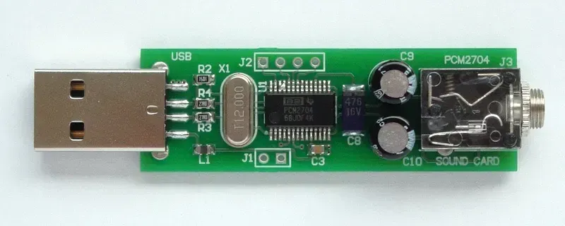
Ensuring the impeccable performance of Digital Sound Card PCBs necessitates rigorous testing and validation processes. These procedures are critical to verifying that the PCB design and manufacturing meet stringent audio quality standards, maintain signal integrity, and operate reliably under various conditions. Without comprehensive testing, even the most meticulously designed sound card PCB can introduce artifacts or fail prematurely, undermining the entire audio system's performance. At Zero One Solution Limited, our validation protocols are designed to identify and rectify potential issues proactively, guaranteeing an optimal audio experience for the end-user.
At Zero One Solution Limited, we understand that exceptional audio quality hinges on the precision and integrity of the underlying PCB. As a leading PCB solution provider with a decade of expertise, we are dedicated to empowering innovators in the digital sound card industry, offering a seamless, one-stop service from initial design consultation to rapid prototyping, manufacturing, and assembly, ensuring your audio products achieve unparalleled performance and market readiness.
Partner with Zero One Solution Limited to transform your digital sound card concepts into reality with unmatched speed, precision, and acoustic fidelity. Our integrated approach and deep industry knowledge make us the ideal choice for developers seeking a reliable and high-performance PCB solution partner.
Understanding the intricacies of Digital Sound Card PCBs is crucial for achieving superior audio performance. This FAQ section addresses common queries regarding their design, manufacturing, and general considerations, providing clear and concise answers to help both enthusiasts and professionals navigate the complexities of audio circuit board technology.
In conclusion, the journey to achieving exceptional digital audio performance begins with a meticulously designed and manufactured PCB. Zero One Solution Limited is dedicated to providing comprehensive PCB solutions tailored to the unique requirements of digital sound cards. From initial design to final assembly, our expertise ensures that your audio projects benefit from optimal signal integrity, minimal noise, and superior reliability. Whether you're developing professional audio equipment, high-end gaming systems, or advanced multimedia applications, our solutions are engineered to elevate your audio experience. Contact Zero One Solution Limited today to discover how our PCB solutions can transform your digital sound card designs into reality. Let us be your trusted partner in achieving audio excellence.

