Electronic resistors, the unsung heroes of the electronic world, are pivotal in controlling the flow of electricity, much like traffic signals direct cars. These seemingly simple components are essential in all electronic circuits, from smartphones to complex industrial machinery. This article will dissect their types, functions, and applications, guiding you through the intricacies of electronic resistors, connecting theory to real-world relevance.
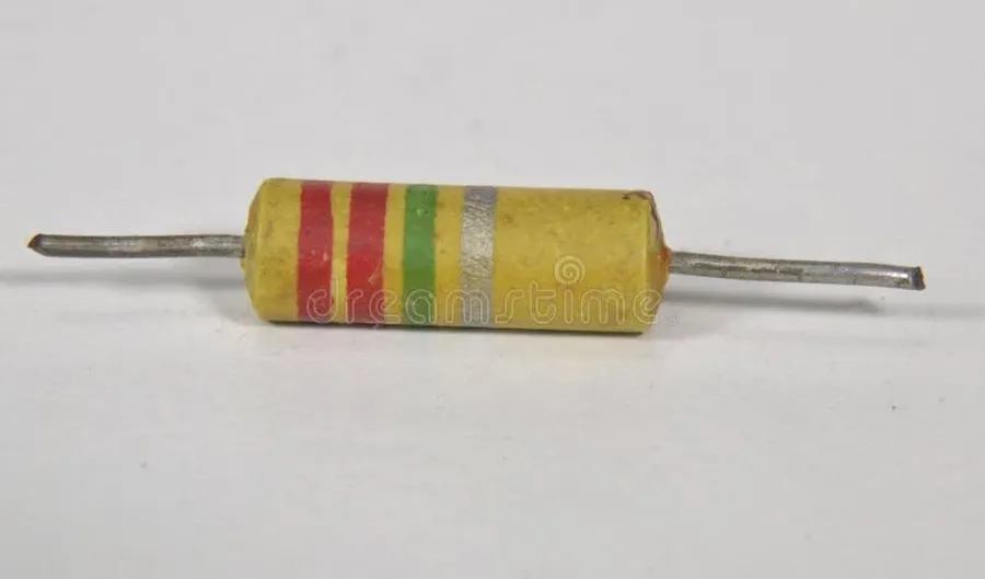
Electronic resistors are fundamental passive two-terminal components designed to impede the flow of electrical current within a circuit. Their primary function is to introduce a specific amount of resistance, which is measured in ohms (Ω), thereby controlling current, adjusting signal levels, and ensuring proper signal termination in transmission lines. The strategic use of resistors is crucial in electronic circuit design, as they enable precise control over voltage and current, essential for the reliable operation of virtually all electronic devices.
At the core of understanding electronic resistors lies the fundamental concept of resistance, measured in ohms (Ω), which quantifies a material's opposition to the flow of electric current. This opposition is crucial in controlling current flow within electronic circuits. Ohm's Law provides the mathematical relationship that defines this behavior, connecting voltage (V), current (I), and resistance (R).
Ohm's Law, expressed as V = I * R, dictates that the voltage across a resistor is directly proportional to the current flowing through it, with the proportionality constant being the resistance. This fundamental principle allows engineers to accurately predict and design circuits by establishing the relationship between these three critical variables.
| Parameter | Symbol | Unit | Description |
|---|---|---|---|
| Voltage | V | Volts (V) | Electrical potential difference |
| Current | I | Amperes (A) | Rate of flow of electric charge |
| Resistance | R | Ohms (Ω) | Opposition to current flow |
Applying Ohm's Law in circuit analysis involves algebraic manipulation to solve for the unknown parameter given the other two. For instance, if we know the voltage across a resistor and its resistance, we can determine the current flowing through it by rearranging the formula to I = V / R. Conversely, knowing the voltage and current allows for the calculation of resistance using R = V / I. This adaptability enables engineers to design circuits with specific operating characteristics.
Understanding these relationships is essential for controlling the operation of circuits, making precise calculations of current, voltage, and resistance. This includes series and parallel circuit calculations which are integral to electrical engineering practice. These applications will be detailed further.
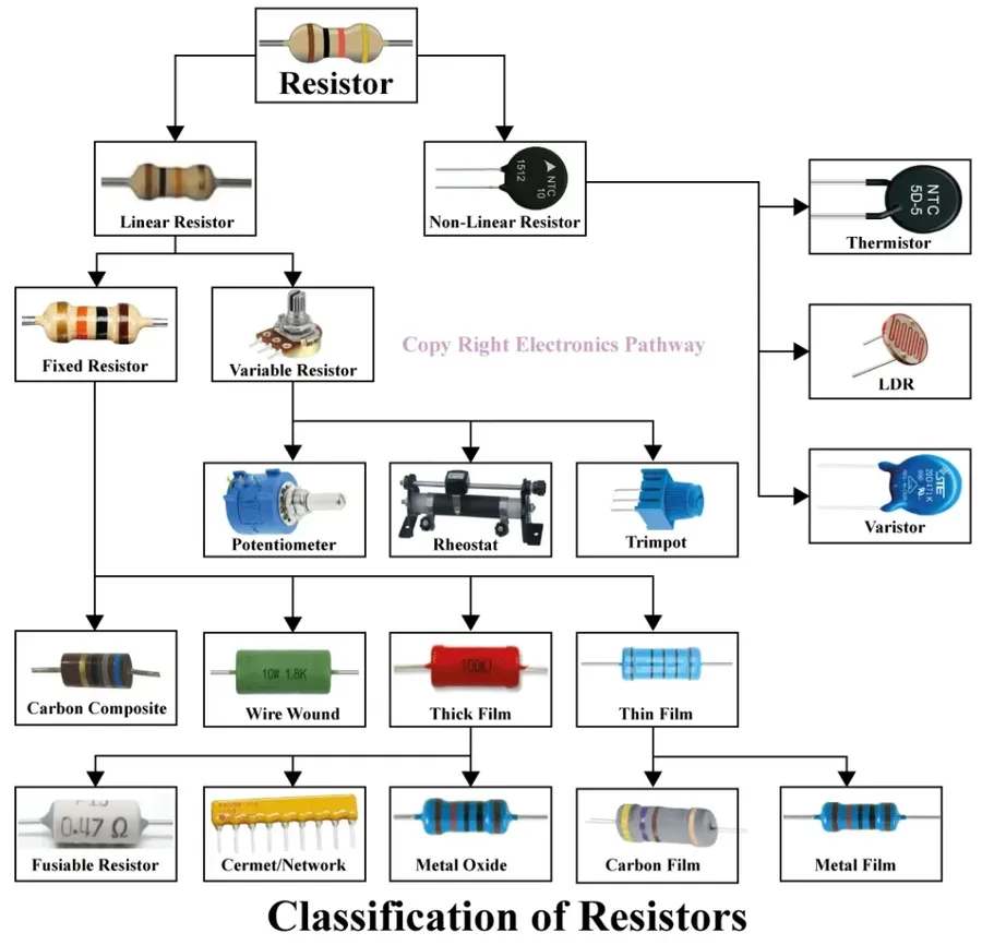
Electronic resistors are manufactured in various types, each with unique characteristics that make them suitable for different applications. These variations primarily revolve around the material used for the resistive element and the construction method, influencing parameters like tolerance, power rating, temperature coefficient, and stability. Understanding these differences is crucial for selecting the appropriate resistor for any specific electronic circuit design.
| Resistor Type | Resistive Element | Tolerance | Power Rating | Temperature Coefficient | Typical Applications | Advantages | Disadvantages |
|---|---|---|---|---|---|---|---|
| Carbon Film | Carbon film deposited on a ceramic substrate | ±2% to ±5% | Low to medium (typically up to 2W) | Moderate (around ±200 to ±1000 ppm/°C) | General-purpose use, low-cost applications | Low cost, widely available | Lower stability, higher temperature coefficient, can be noisy |
| Metal Film | Thin metallic film deposited on a ceramic substrate | ±0.1% to ±1% | Low to medium (typically up to 2W) | Low (around ±50 to ±100 ppm/°C) | Precision applications, audio circuits, sensitive electronics | High precision, low temperature coefficient, low noise | More expensive than carbon film resistors |
| Wire-Wound | Metallic wire wound around a ceramic core | ±0.01% to ±5% | High (up to several hundred watts) | Low (around ±20 to ±50 ppm/°C) | Power circuits, high-current applications | High power rating, high precision, stable | Large size, high inductance at high frequencies |
| Surface Mount (SMD) | Various film types (thick film, thin film) on a small ceramic substrate | ±0.1% to ±5% | Low (typically under 1W) | Varies depending on the material, moderate to low | Modern electronics, compact designs, high-density boards | Small size, suitable for automated assembly | Difficult to handle manually, higher cost |
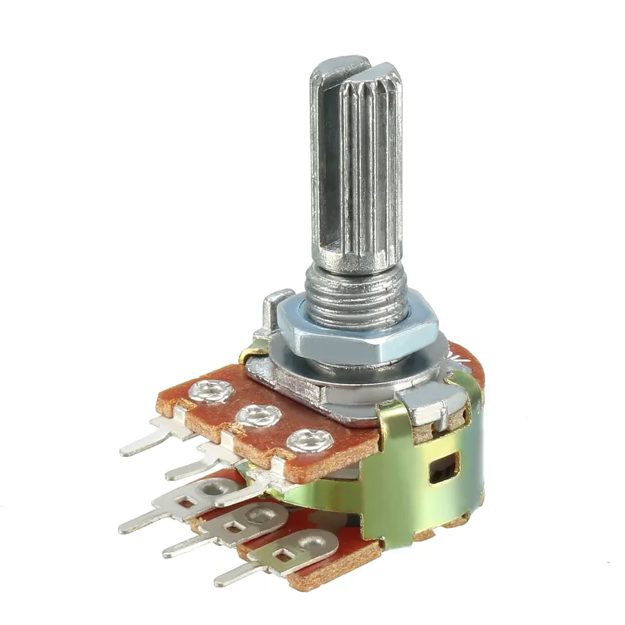
Electronic resistors are broadly classified into two categories: fixed and variable. Fixed resistors offer a constant, predetermined resistance value, while variable resistors, such as potentiometers and rheostats, allow for adjustable resistance. This distinction is critical for circuit design, enabling both static and dynamic control of electrical current.
| Characteristic | Fixed Resistors | Variable Resistors |
|---|---|---|
| Resistance Value | Constant, predetermined | Adjustable within a range |
| Types | Carbon film, metal film, wire-wound, etc. | Potentiometers, rheostats, trimmers |
| Application | Current limiting, voltage division, pull-up/pull-down | Volume control, calibration, dimming |
| Adjustability | None | Manually or electronically adjusted |
| Cost | Generally Lower | Generally higher due to mechanical parts |
The choice between fixed and variable resistors depends on the specific requirements of the electronic circuit. Fixed resistors are the workhorse of most circuits, used for tasks such as setting bias currents or creating voltage dividers. Variable resistors, on the other hand, provide flexibility where dynamic adjustment is needed. For example, a potentiometer in a volume control circuit allows the user to adjust the loudness by changing the resistance, while rheostats are used in motor speed control applications. Their adjustability adds a layer of functionality not available with fixed resistors.
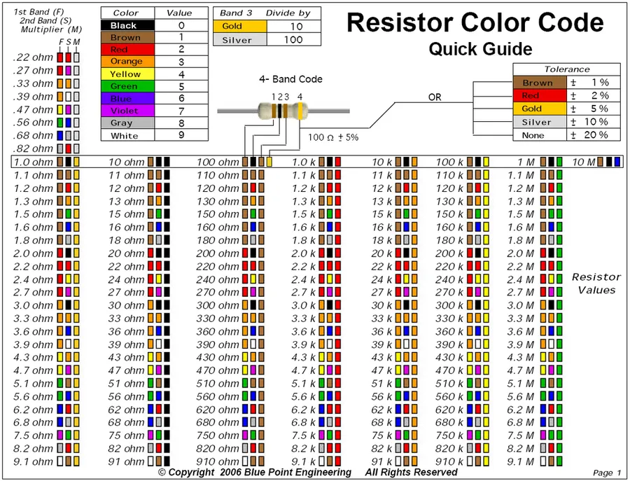
Electronic resistors are often too small to print their resistance value directly, thus a color-coding system is used to denote their resistance and tolerance. Understanding these codes allows for quick identification of resistor values without the need for complex measuring equipment. This section details how to accurately read both axial lead resistor color codes and surface mount resistor (SMD) markings.
Axial lead resistors typically use 4 or 5 color bands to indicate their resistance value and tolerance. The bands are read from left to right, starting with the band closest to one end of the resistor. The first two bands represent the first two digits of the resistance value, the third band represents the multiplier, and the fourth band indicates the tolerance. For 5-band resistors, the third band is also a digit of the resistance value and the fourth band is the multiplier, and the fifth band is the tolerance.
| Color | Digit (1st, 2nd band) | Multiplier (3rd band) | Digit (3rd band, 5 band resistors) | Tolerance (4th/5th band) |
|---|---|---|---|---|
| Black | 0 | x 1 | 0 | - |
| Brown | 1 | x 10 | 1 | ± 1% |
| Red | 2 | x 100 | 2 | ± 2% |
| Orange | 3 | x 1,000 | 3 | - |
| Yellow | 4 | x 10,000 | 4 | - |
| Green | 5 | x 100,000 | 5 | ± 0.5% |
| Blue | 6 | x 1,000,000 | 6 | ± 0.25% |
| Violet | 7 | x 10,000,000 | 7 | ± 0.1% |
| Gray | 8 | x 0.01 | 8 | ± 0.05% |
| White | 9 | - | 9 | - |
| Gold | - | x 0.1 | - | ± 5% |
| Silver | - | x 0.01 | - | ± 10% |
| None | - | - | - | ± 20% |
Surface mount resistors are typically marked with a numerical code. A three-digit code indicates the resistance value, where the first two digits are the significant figures and the third is the multiplier. For example, '103' denotes a 10kΩ resistor (10 x 10^3), and '221' indicates a 220Ω (22 x 10^1). Some SMD resistors use a four-digit code which follows a similar logic.
When reading color codes, the gold or silver band is usually placed on the right, as they almost always denote tolerance. Sometimes the color bands are difficult to identify. Using a multimeter, or comparing to an known reference can help identify the correct value. In addition, for SMD resistors, online tools and datasheets for the specific part manufacturer are invaluable in identifying resistor values where the markings are unclear.
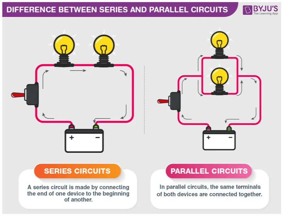
Understanding how resistors behave in series and parallel configurations is fundamental to electronic circuit design. These configurations determine the overall resistance of a circuit and directly impact current and voltage distribution. Mastering these concepts is crucial for designing functional and efficient circuits.
The total resistance, current flow, and voltage distribution differ significantly between these two connection types. In series, the total resistance is the sum of individual resistances, while in parallel, the reciprocal of the total resistance equals the sum of reciprocals of individual resistances. These differences have practical implications that designers need to carefully consider.
| Characteristic | Series Connection | Parallel Connection |
|---|---|---|
| Total Resistance (R_total) | R_total = R1 + R2 + ... + Rn | 1/R_total = 1/R1 + 1/R2 + ... + 1/Rn or R_total = (R1*R2)/(R1+R2) for 2 resistors |
| Current | Same through all resistors | Divides among resistors |
| Voltage | Divides across resistors | Same across all resistors |
In a series circuit, the current remains constant throughout all resistors, and the total resistance is the arithmetic sum of individual resistances. This configuration effectively increases the overall resistance of the circuit. The voltage applied is divided across each resistor in proportion to their individual resistances. Therefore, higher resistance resistors will have a greater voltage drop.
In contrast, a parallel configuration connects resistors side-by-side, providing multiple paths for current flow. The total resistance is less than the smallest resistance in the parallel network. The voltage drop is the same across all resistors but the current is divided according to Ohm's law; lower resistance resistors will have a greater current flow. This characteristic of parallel circuits is used in various applications such as providing parallel paths for redundant or additional load capability.
These fundamental concepts of series and parallel resistor connections form the basis for designing more complex circuits. Understanding the different behaviors of these configurations in circuit design is crucial to achieving the correct parameters for the desired functionality. An example would be a simple voltage divider circuit, which uses series resistors to reduce a source voltage to a desired value.
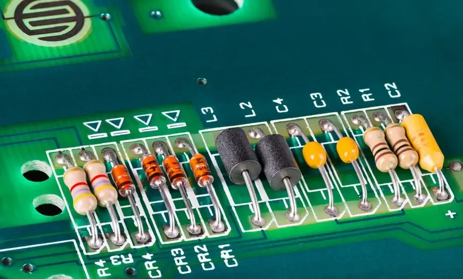
Electronic resistors are fundamental components in nearly all electronic circuits, serving diverse and critical functions. Their primary role is to control current flow, enabling precise circuit behavior. Beyond this basic function, resistors facilitate various complex operations, from voltage division and current limiting to signal filtering and motor speed control.
This section addresses common queries regarding electronic resistors, providing clear and concise answers to enhance understanding of their function, types, and applications.
Selecting the appropriate electronic resistor is crucial for optimal circuit performance and reliability. This process involves carefully considering several key factors, including resistance value, tolerance, power rating, and temperature coefficient, each of which plays a vital role in circuit operation. Furthermore, heat dissipation, longevity, and cost must also be evaluated to ensure the selected resistor meets both functional and practical requirements.
| Factor | Description | Implication |
|---|---|---|
| Resistance Value | The desired electrical resistance in ohms. | Directly affects current flow; must match circuit needs. |
| Tolerance | The allowable deviation from the stated resistance value. | Impacts precision of circuit performance, especially in sensitive applications. |
| Power Rating | The maximum power the resistor can dissipate without damage. | Insufficient rating can lead to overheating and failure. |
| Temperature Coefficient | Change in resistance per degree Celsius. | Can affect circuit stability in varying temperature environments. |
| Heat Dissipation | Ability of the resistor to release heat to its environment | Overheating may result in component degradation, instability, or failure. |
| Longevity | Expected lifespan of the resistor under typical operating conditions. | Impacts long-term reliability of the circuit, requiring higher quality resistors in critical applications. |
| Cost | Expense of the resistor; influences overall project budget. | Higher precision and higher quality tend to increase cost, but may be necessary for certain applications. |
When selecting a resistor, the resistance value is typically dictated by the circuit design. However, selecting the appropriate tolerance, power rating and temperature coefficient requires a more nuanced approach. For instance, applications requiring high precision, such as measurement circuits, demand low tolerance resistors. The power rating should always exceed the calculated power dissipation by a safety margin to prevent overheating and premature failure. Also, consider the operating environment when evaluating the temperature coefficient; applications operating in a wide temperature range require resistors with a low temperature coefficient. Heat dissipation considerations are also important, ensure adequate heat dissipation is addressed in the design, and consider using heat sinks if needed. Balancing these technical requirements with cost considerations is essential for cost-effective and reliable circuit design.
Electronic resistors are indeed fundamental to every electronic circuit, playing a crucial role in controlling current, voltage, and signal flow. Understanding the types, functions, and applications of these seemingly simple components is essential for anyone involved in electronics. From the ubiquitous carbon film resistor to the precision of surface mount devices, each type serves a specific purpose, enabling the complex functionalities we rely on daily. By comprehending these principles, readers can not only troubleshoot issues but also design and optimize electronic circuits for enhanced performance, longevity, and efficiency, continuing the advancement of electronic technology.

