In today's rapidly evolving tech landscape, flexibility isn't just a desirable trait—it's a necessity. Flex printed circuits, or flexible PCBs, are at the forefront of this movement, bridging the gap between rigid electronics and dynamic applications. From wearable devices to intricate medical instruments, these circuits are reshaping how we interact with technology, demonstrating a fusion of engineering and modern life, where adaptability is crucial.
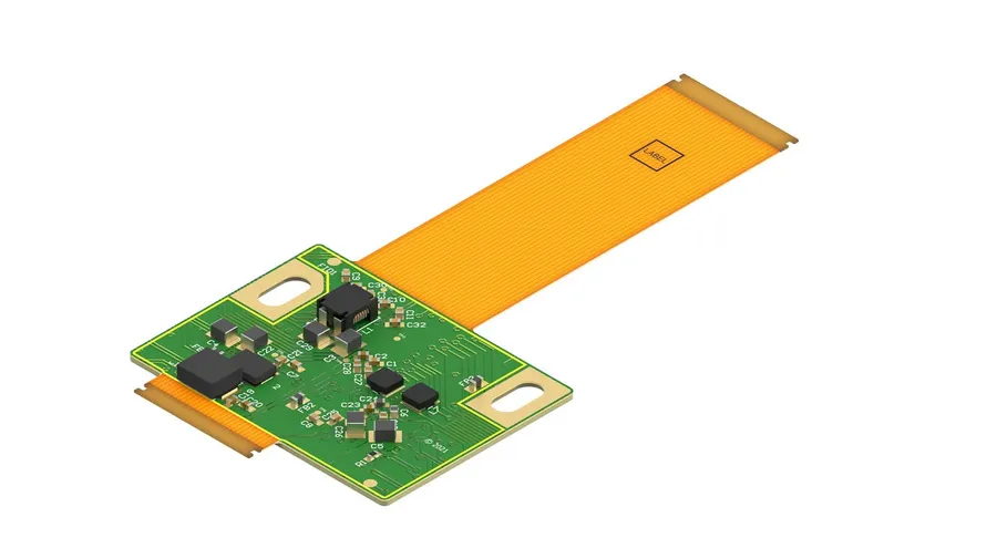
Flex printed circuits (FPCs), also known as flexible printed circuits, are bendable electronic circuits constructed on flexible substrates, differing fundamentally from rigid printed circuit boards (PCBs). This flexibility enables unique applications where traditional rigid boards are unsuitable. FPCs are not just flexible in the literal sense; they introduce transformative capabilities in electronic design and integration.
The core structure of an FPC consists of a thin, flexible substrate material, typically a polymer film, upon which conductive traces are patterned using copper. Additional layers of adhesive and protective coatings may be added for durability and insulation. Unlike rigid PCBs, FPCs can conform to complex shapes, bend, and even fold without compromising electrical performance. This adaptability opens avenues for compact and intricate electronic designs.
| Feature | Flex Printed Circuits (FPCs) | Rigid Printed Circuit Boards (PCBs) |
|---|---|---|
| Substrate Material | Flexible Polymer (e.g., Polyimide, PET) | Rigid Materials (e.g., FR-4) |
| Flexibility | Highly Flexible, Bendable | Rigid, Cannot Bend |
| Shape Conformance | Conforms to Complex Shapes | Fixed Shape |
| Applications | Wearable tech, automotive, medical devices, aerospace | Computers, consumer electronics, industrial equipment |
| Weight | Lower | Higher |
| Durability | High bending and vibration resistance | Limited flexibility and vibration resistance |
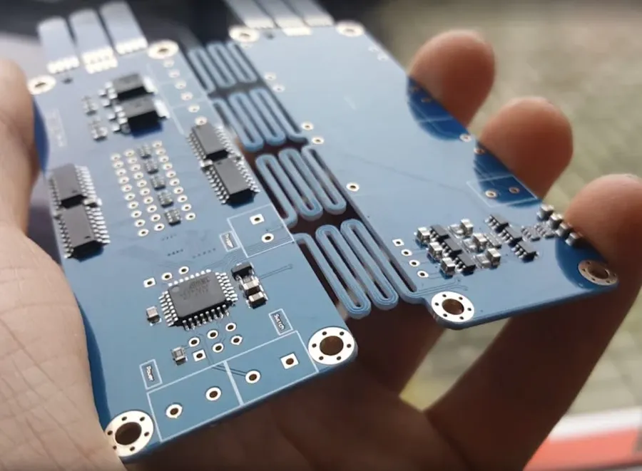
Flex printed circuits (FPCs) offer a multitude of advantages over traditional rigid PCBs, primarily stemming from their inherent flexibility. These benefits translate to enhanced design possibilities, increased efficiency, and improved performance across a wide array of applications. The ability to conform to various shapes and fit into tight spaces makes them essential for modern electronic designs, where space is at a premium and design constraints are complex.
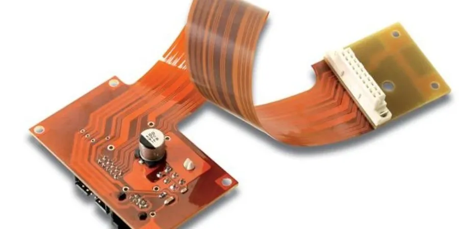
The performance and reliability of flex printed circuits (FPCs) are intrinsically linked to the materials used in their construction. The selection of substrate, conductive layers, and other critical components is a pivotal decision that directly impacts the flex circuit's ability to withstand bending, temperature variations, and demanding electrical requirements. The correct choice of materials is critical to ensuring optimal functionality and longevity.
| Material | Description | Advantages | Disadvantages | Typical Applications |
|---|---|---|---|---|
| Polyimide (Kapton) | A high-performance polymer known for its exceptional thermal stability and chemical resistance. | Excellent temperature resistance, high mechanical strength, chemical resistance. | Higher cost compared to other materials, can be sensitive to moisture absorption. | High-reliability applications, aerospace, automotive |
| Polyester (PET) | A widely used, low-cost thermoplastic polymer. | Cost-effective, good chemical resistance, flexible. | Lower temperature resistance compared to polyimide, less durable. | Consumer electronics, low-cost applications, disposable devices. |
| Liquid Crystal Polymer (LCP) | A high-performance polymer with excellent electrical and mechanical properties. | Low moisture absorption, high dimensional stability, good electrical performance at high frequencies | Higher cost, can be challenging to process. | High-frequency applications, advanced communication systems. |
| Copper Cladding | The primary conductive material used for traces and vias. | Excellent electrical conductivity, readily available, good solderability. | Can be susceptible to corrosion if not protected, relatively heavy compared to other materials. | All types of flex circuit applications |
| Adhesives | Used to bond layers of the flex circuit together. | Provides mechanical bonding strength, can be conductive or non-conductive. | Can be a source of delamination if not properly applied, can outgas at high temperatures. | All types of flex circuit applications |
| Coverlays | Protective layers applied to the circuit to protect it from physical damage and moisture. | Provides physical protection, environmental protection, insulation | Adds to the overall thickness and cost. | All types of flex circuit applications |
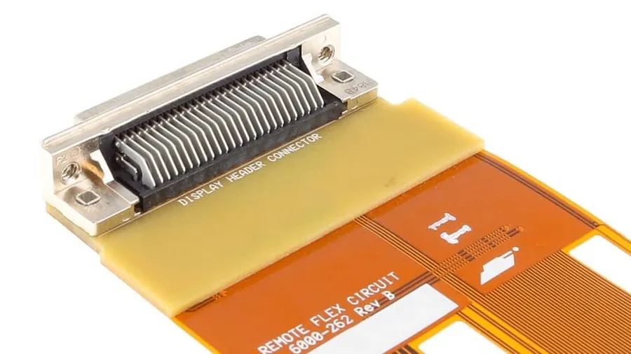
Designing flexible printed circuits (FPCs) demands careful attention to several factors that differ significantly from rigid PCB design. These considerations ensure the FPC functions reliably under various mechanical and environmental stresses. Key design aspects include trace routing, bend radii, conductor thickness, layer count, and environmental compatibility. A robust design is crucial for the FPC's longevity and performance in its intended application.
| Design Consideration | Description | Impact on FPC Performance |
|---|---|---|
| Trace Routing | Path and configuration of conductive traces on the flexible substrate. | Affects signal integrity, impedance, and flexibility. Improper routing can lead to signal loss or mechanical stress. |
| Bend Radii | Minimum radius to which the FPC can be bent without damage. | Determines the flexibility and service life of the FPC. Exceeding the minimum bend radius can cause conductor cracks or delamination. |
| Conductor Thickness | Thickness of the copper or other conductive layers. | Affects the current carrying capacity and flexibility. Thicker conductors offer better current capacity but reduce flexibility. |
| Layer Count | Number of conductive and dielectric layers in the FPC. | Determines the complexity and cost. Higher layer counts allow for more complex circuits but increase the thickness and reduce flexibility. |
| Environmental Factors | Temperature, humidity, and chemical exposure the FPC will encounter. | Impacts material selection and long-term reliability. Incorrect material selection can lead to material degradation and circuit failure. |
Practical design guidelines include using teardrop pads at trace junctions to reduce stress concentrations, minimizing sharp bends and corners to prevent stress risers, and ensuring proper spacing between traces to avoid shorts. The specific requirements vary by application, but following these guidelines will help ensure the reliability and longevity of the flex printed circuits.
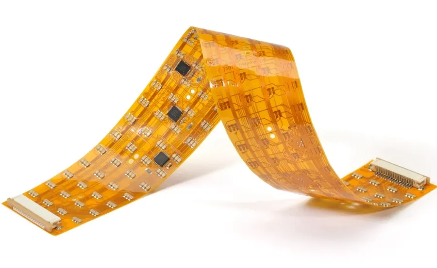
Flex printed circuits (FPCs) have become indispensable across a wide range of industries due to their flexibility, space-saving capabilities, and reliability. This section details how FPCs are utilized in various sectors, highlighting their critical role in modern technology.
The unique attributes of FPCs, such as their ability to conform to complex shapes and withstand repetitive bending, make them ideal for applications where traditional rigid PCBs are unsuitable. This adaptability has led to their widespread adoption in diverse fields, revolutionizing product design and functionality.
| Industry | Application Examples | Specific Use Cases |
|---|---|---|
| Consumer Electronics | Smartphones, Laptops, Wearable Tech | Interconnecting displays, cameras, keyboards, and sensors in a compact and flexible manner. |
| Automotive | Advanced Driver-Assistance Systems (ADAS), In-Car Infotainment | Connecting sensors, control units, and display modules within constrained spaces of vehicles. |
| Medical | Implantable Devices, Diagnostic Equipment | Enabling miniaturization and biocompatibility in devices such as pacemakers, hearing aids, and surgical tools. |
| Aerospace | Satellite Systems, Aircraft Avionics | Providing lightweight, reliable interconnections in space and aircraft systems, reducing overall weight and improving performance. |
| Industrial | Robotics, Industrial Control Systems | Facilitating complex wiring and movement in robotic arms, machinery controls, and automation equipment. |
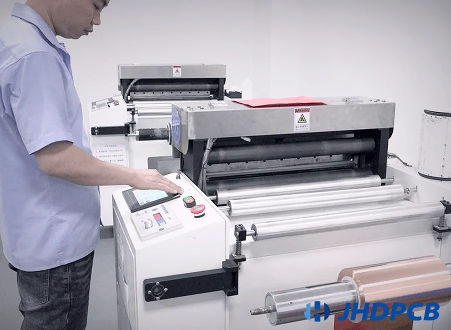
The fabrication of flex printed circuits (FPCs) is a complex process demanding high precision and stringent quality control. It involves a series of intricate steps from initial design to final assembly, each crucial to the functionality and reliability of the circuit.
The effective utilization of flexible printed circuits (FPCs) hinges significantly on the selection and implementation of appropriate connectors and assembly techniques. These elements are critical not only for ensuring reliable electrical connections but also for maintaining the mechanical integrity and overall performance of FPC-based electronic systems. The following section details these vital aspects, encompassing connector types, mounting procedures, and their influences on circuit performance.
| Connector Type | Description | Typical Application | Advantages | Disadvantages |
|---|---|---|---|---|
| ZIF (Zero Insertion Force) Connectors | Connectors that require minimal force for insertion and removal, often utilizing a clamping mechanism. | High-density applications, situations requiring frequent disconnections. | Reduces stress on FPC, easy to connect and disconnect. | Can be larger in size, more complex. |
| FFC/FPC Connectors | Designed specifically for flat flexible cables and printed circuits, often featuring a locking mechanism. | Common in consumer electronics, portable devices. | Compact size, reliable connection | Can be sensitive to misalignment, requires precise insertion |
| Soldered Connections | Directly soldering FPC traces to pads or other components. | Permanent connections in high-reliability applications. | High mechanical strength, low electrical resistance. | Difficult to repair, requires soldering expertise |
| Crimped Connectors | Connectors that use pressure to establish a connection between FPC and the connector. | Automotive applications, rugged environments. | Robust connection, suitable for harsh conditions | Requires special crimping tools, not easily disassembled |
Proper mounting and assembly of flex circuits are essential for avoiding damage and ensuring operational reliability. Mounting methods range from adhesive bonding to mechanical fasteners, each with its own set of advantages and disadvantages. Considerations must be given to stress distribution, thermal expansion, and the application’s mechanical requirements. Improper assembly can lead to issues such as trace damage, connection failures, and premature wear.
The choice of connector and assembly method directly influences the electrical performance of FPCs. Connectors can introduce contact resistance, signal reflections, and electromagnetic interference. Assembly methods can affect trace integrity and overall system robustness. Thus, meticulous design and assembly are needed to optimize FPC performance.
This section addresses common questions about flexible printed circuits (FPCs), clarifying their nature, applications, and design considerations. Understanding these frequently asked questions can provide clarity on the versatility and advantages of FPC technology.
The field of flexible printed circuits (FPCs) is rapidly evolving, driven by innovations in materials, manufacturing techniques, and emerging applications. These advancements are paving the way for more versatile, durable, and integrated electronic solutions across various industries.
Flex printed circuits are revolutionizing industries with their unparalleled ability to adapt to complex geometries and dynamic environments. From simple consumer gadgets to advanced medical devices, they provide innovative solutions that previously were impossible with traditional rigid PCBs. As technology progresses, the integration of flex printed circuits is set to expand, leading to more flexible, reliable, and innovative electronic devices. Understanding these circuits’ potential allows us to foresee a future where design limitations are further minimized, fostering growth and adaptation to the changing needs of the tech world.

