
As the global demand for renewable energy surges, wind turbines are evolving into sophisticated data-gathering hubs. The secret to this transformation isn't just in the turbine blades—it is in the printed circuit board (PCB) architecture. Traditional control boards are being pushed to their breaking point; learn how the next generation of power electronics is solving critical reliability challenges.
The Shifting Landscape of Wind Turbine Power Electronics
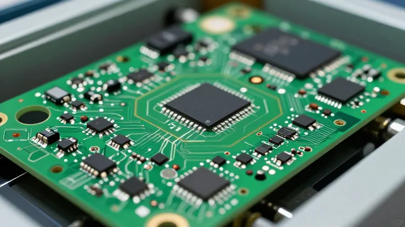
Transitioning from Legacy to High-Density Architectures
Wind turbine controllers are shifting from monolithic, low-complexity boards to sophisticated high-density interconnect (HDI) platforms. As turbines grow in physical size and capacity, the power electronics managing grid synchronization and conversion must handle significantly higher thermal loads and complex switching frequencies. This necessitates a transition to multi-layer PCBs that support advanced gallium nitride (GaN) and silicon carbide (SiC) power semiconductors, which offer superior efficiency compared to traditional silicon-based components.
| Feature | Legacy Systems | Next-Gen Systems |
|---|---|---|
| Switching Frequency | Low (kHz range) | High (MHz potential) |
| Material Composition | Standard FR-4 | Thermal-conductive substrates |
| Grid Integration | Passive/Reactive | Active AI-driven feedback |
| Design Density | Through-hole heavy | High-Density Interconnect (HDI) |
Critical Challenges in Modern Controller Design
- How does smart-grid integration impact board space?
Modern controllers require additional IoT sensors and communication modules, demanding miniaturization of control logic circuits while maintaining high-voltage isolation zones on the same board. - What role do wide-bandgap semiconductors play?
Materials like SiC and GaN allow for higher power densities and reduced switching losses, though they impose stricter requirements on PCB layout and heat dissipation strategies. - Why is board-level thermal management now a primary concern?
Increased power density in compact controller enclosures creates localized hotspots that can degrade dielectric performance, requiring embedded copper coins and advanced thermal vias in the PCB design.
Limitations of Traditional Rigid PCB Architectures
The Vulnerability of Rigid Substrates to Dynamic Stress
Rigid PCBs, typically constructed from FR-4 laminate, are inherently ill-suited for the dynamic, high-vibration environments characteristic of wind turbine nacelles. In modern high-capacity turbines, constant mechanical strain from blade rotation and turbulent wind loading leads to cyclical stress on solder joints and component interconnects. Because rigid boards lack the flexibility to absorb these mechanical oscillations, they are prone to structural failures such as solder joint fracturing, copper trace cracking, and delamination of the PCB layers over extended operational life cycles.
Comparative Analysis: Rigid vs. Flexible/Advanced Architectures
| Failure Metric | Rigid FR-4 PCB | Advanced Flexible/Hybrid PCB |
|---|---|---|
| Vibration Resistance | Low; prone to solder cracking | High; dissipates mechanical energy |
| Thermal Cycling | High risk of CTE mismatch | Excellent thermal expansion handling |
| Space Optimization | Bulky, requires cabling | Compact, eliminates connectors |
| Durability | Subject to fatigue failure | High reliability in harsh environments |
Key Challenges in Harsh Environmental Deployment
- Coefficient of Thermal Expansion (CTE) Mismatch
The disparity between the thermal expansion rates of the ceramic components and the rigid epoxy-glass substrate often leads to internal stress concentrations during extreme temperature swings, ultimately resulting in via barrel cracking. - Connector Reliability
Traditional designs rely heavily on multiple mechanical connectors to bridge subsystems. These connectors act as primary failure points in high-vibration settings, where fretting corrosion can lead to intermittent electrical connections or signal loss. - Thermal Management Limitations
Rigid boards offer limited heat dissipation paths, often requiring bulky heat sinks that increase mass and susceptibility to gravity-induced fatigue in vertical or angled mounts.
The Rise of Rigid-Flex Technology in Industrial Controls
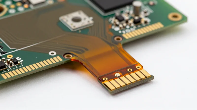
The Rise of Rigid-Flex Technology in Industrial Controls
As wind turbine controllers demand higher processing density and reduced physical footprints, rigid-flex PCBs have emerged as the superior solution for nacelle-based electronics. By integrating rigid boards with flexible polyimide layers into a singular, monolithic assembly, manufacturers can eliminate bulky connectors, cables, and solder joints—the primary failure points in traditional designs.
Optimizing Space and Mechanical Integrity
In the confined, high-vibration environment of a turbine nacelle, structural failure often stems from wiring fatigue at connection terminals. Rigid-flex technology allows for complex 3D routing that conforms to internal chassis geometry, effectively isolating sensitive components from structural mechanical shock. This monolithic approach reduces the overall controller mass by up to 30%, which is critical for reducing structural strain on the tower and optimizing maintenance overhead.
| Feature | Rigid PCB with Cables | Rigid-Flex PCB |
|---|---|---|
| Mechanical Reliability | Low (Connector Failure) | High (Solder-less Flex) |
| Space Efficiency | Moderate | Excellent (3D Conformity) |
| Vibration Tolerance | Susceptible to Fatigue | Exceptional (Damping Properties) |
| Assembly Complexity | High (Manual Wiring) | Low (Automated Integration) |
Frequently Asked Questions
- How does rigid-flex technology improve signal integrity?
By replacing high-impedance cabling and multiple connectors with continuous conductive paths, rigid-flex boards drastically reduce signal loss, crosstalk, and EMI susceptibility. - Does rigid-flex justify the higher manufacturing cost?
While unit costs are higher than standard boards, the total cost of ownership is reduced through streamlined assembly, lower failure rates in the field, and reduced maintenance cycles for nacelle electronics. - Is rigid-flex material resistant to turbine operating temperatures?
Yes, high-grade polyimide substrates used in rigid-flex construction maintain stable dielectric properties across a wider thermal range compared to traditional FR4 laminates, preventing cracking during rapid temperature cycles.
Embedded Component Tech: Maximizing Density and Thermal Control
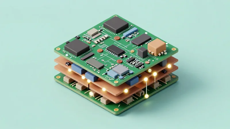
The Shift Toward Embedded Component Substrates
Embedding active and passive components within the PCB stack-up represents a paradigm shift from traditional surface-mount technology (SMT). By placing resistors, capacitors, and ICs directly into the core or internal layers of the board, engineers can drastically reduce parasitic inductance and resistance. This architectural change allows for shorter trace lengths, which is critical for maintaining high signal integrity in the high-speed IoT sensors essential for real-time turbine vibration analysis and predictive maintenance.
Thermal Dynamics and Heat Dissipation
In the confined, high-vibration environment of a nacelle, thermal management is paramount. Conventional PCBs often suffer from localized 'hot spots' where SMT components restrict heat flow. Embedded technology allows the board itself to act as a heat sink, utilizing copper thermal vias that connect internal components directly to the power and ground planes. This improves the overall thermal dissipation profile, preventing premature component failure under extreme operational loads.
| Feature | Surface-Mount Technology | Embedded Component Technology |
|---|---|---|
| Trace Length | Longer; higher impedance | Short; optimized signal path |
| Thermal Management | External via path required | Internal substrate-integrated heat sinking |
| Board Density | Limited by footprint | High; multi-dimensional utilization |
| Reliability | Subject to solder joint fatigue | Superior; encapsulated protection |
Frequently Asked Questions on Integration
- How does embedding components improve reliability in wind turbines?
By encapsulating components within the PCB, the joints are shielded from the extreme mechanical stresses and vibrations experienced in wind turbine nacelles, effectively eliminating common solder joint fractures. - What are the primary challenges of embedded PCB manufacturing?
The primary hurdles include increased initial design complexity, the need for precise registration during layer lamination, and the difficulty of inspecting or replacing a failed component once integrated into the substrate. - Does embedding components justify the higher manufacturing cost?
For mission-critical IoT sensor applications in wind power, the reduction in maintenance frequency, increased board longevity, and improved data acquisition precision offer a strong long-term return on investment.
Meeting High-Reliability Standards in Harsh Environments
Engineered Resilience: Protecting PCBs from Harsh Elements
Offshore wind turbines represent one of the most punishing environments for electronic assemblies, where a combination of saline mist, extreme humidity, and constant mechanical vibration can compromise standard PCB designs in weeks. To meet high-reliability standards, manufacturers are shifting toward specialized substrate materials and advanced conformal coating technologies designed to achieve an operational lifespan exceeding 20 years. By utilizing high-Tg (glass transition temperature) laminates, controllers can maintain mechanical stability despite the extreme thermal cycling common in nacelle-mounted power electronics.
Material Selection and Environmental Hardening
| Challenge | Mitigation Strategy | Technological Outcome |
|---|---|---|
| Salt-Mist Corrosion | Parylene Coating | Hermetic Seal equivalent protection |
| High-Frequency Vibration | Dampening Substrates | Fatigue-resistant solder joints |
| High Humidity | Ceramic-Filled Laminates | Low moisture absorption rates |
Frequently Asked Questions Regarding Offshore Reliability
- Why are standard FR-4 materials often insufficient for offshore applications?
Standard FR-4 materials typically exhibit higher moisture absorption rates and lower thermal stability, leading to potential delamination or electrical shorting when exposed to the high-humidity, saline-rich air of offshore sites. - What role does conformal coating play in long-term reliability?
Conformal coating acts as a critical dielectric barrier against moisture, airborne contaminants, and fungal growth; for high-end wind applications, vacuum-deposited materials like Parylene are preferred over traditional acrylic sprays for superior coverage. - How is vibration-induced solder failure mitigated?
Engineers utilize underfill materials and reinforced mounting points to distribute mechanical stress across the board surface, ensuring that solder balls maintain integrity during the continuous oscillating loads of turbine operation.
Powering the IoT-Driven Turbine Monitoring Ecosystem

Data Backbone: High-Bandwidth Architecture
Modern wind turbine controllers must act as edge computing gateways, processing massive streams of vibration, thermal, and acoustic data from hundreds of sensors. To support this, PCBs are transitioning to high-speed, multi-layer designs utilizing low-loss laminate materials such as PTFE or hydrocarbon ceramics. These materials minimize signal attenuation, ensuring that high-frequency data from vibration sensors reaches the processor with minimal latency.
Architectural Strategies for Real-Time Analytics
| Requirement | PCB Solution | Performance Benefit |
|---|---|---|
| Signal Integrity | Differential Impedance Control | Reduced EMI and jitter in sensor data. |
| Edge Processing | High-Density Interconnect (HDI) | Enables smaller, high-performance SoCs near sensors. |
| Data Throughput | Blind/Buried Vias | Allows shorter trace lengths for high-speed signal paths. |
Frequently Asked Questions
- How does PCB architecture support Digital Twins?
Advanced PCBs provide the low-latency processing and reliable data paths necessary to sync real-world turbine sensor data with virtual models in real-time. - Why is trace length critical for IoT sensors?
Shortened trace lengths reduce inductive and capacitive noise, which is vital for capturing subtle harmonic signatures used in early-stage fault detection. - What is the role of the PCB in power-constrained IoT devices?
Modern PCBs use advanced power delivery network (PDN) designs to minimize noise and optimize efficiency, extending the operational life of remote, wireless IoT sensor nodes.
Design Best Practices for Modern Wind Power Controllers
Material Selection for Extreme Environments
Modern controller PCBs must survive temperature cycling from -40°C to +85°C while exposed to corrosive maritime atmospheres. Designers should prioritize high-Tg (glass transition temperature) laminates, such as polyimide or specialized epoxy resins with low coefficient of thermal expansion (CTE) to prevent delamination and via fatigue during mechanical vibrations.
| Parameter | Material Choice | Justification |
|---|---|---|
| Thermal Stability | High-Tg (>170°C) | Resists blistering and cracking during intense vibration cycles. |
| Corrosion Resistance | ENIG / ENEPIG | Provides robust oxidation protection for long-term offshore exposure. |
| Dielectric Loss | Low-Loss Laminate | Maintains high-speed signal integrity for real-time sensor monitoring. |
Thermal Management and Signal Integrity Strategies
Thermal density in modern controllers is increasing due to miniaturized power electronics and high-compute processors. Integrated thermal management, such as heavy copper planes and thermal vias, is essential to disperse heat away from sensitive components. Concurrently, signal integrity must be preserved by employing differential pair routing and strict impedance control to mitigate electromagnetic interference (EMI) generated by the turbine's massive power electronics.
Best Practices FAQ
- How do you mitigate vibration-induced fatigue?
Utilize circular pads on heavy components, ensure adequate copper weight for anchor points, and implement high-reliability surface mount solder techniques combined with conformal coating. - What is the role of conformal coating?
It acts as a primary barrier against humidity and salt-spray ingress, preventing electrochemical migration and short circuits on high-density interconnects. - How is EMI managed in high-power environments?
Use a multi-layer stack-up design with dedicated ground planes acting as shielding, and implement strict keep-out zones between high-voltage switching circuits and sensitive low-voltage control signals.
The Economic Impact: Reducing O&M Costs through Better Electronics
Quantifying the Cost of PCB Failure in Wind Environments
The economic impact of suboptimal PCB design in wind turbine controllers extends far beyond the component cost. When a controller fails in an offshore environment, the financial burden is dominated by logistics, vessel rental, and lost power generation. Transitioning to high-reliability PCB architectures—featuring advanced thermal management and vibration-resistant solder alloys—directly minimizes these unplanned service interventions.
| Failure Driver | Legacy PCB Impact | High-Reliability PCB Impact |
|---|---|---|
| Thermal Stress | Frequent component burnout | Extended component lifespan |
| Vibration/Fatigue | Solder joint cracking | Dampened mechanical resilience |
| Environmental Corrosion | High signal noise/shorting | Superior ingress protection |
Economic Justification for Next-Generation Electronics
Investing in high-performance substrates and ruggedized manufacturing processes provides a clear ROI through reduced Mean Time Between Repairs (MTBR). By leveraging PCBs designed for extreme endurance, operators can shift from reactive maintenance models to predictable, scheduled servicing.
- How do advanced PCBs lower long-term O&M costs?
By minimizing component failure rates and the associated high costs of offshore service vessel deployments and specialized technical labor. - What is the primary ROI driver for upgraded controllers?
Increased uptime and higher Annual Energy Production (AEP) resulting from fewer intermittent signal faults and system-wide controller failures. - Does better PCB technology justify higher initial CAPEX?
Yes, the slight increase in upfront manufacturing costs is typically recovered within 18–24 months due to the drastic reduction in total cost of ownership (TCO) over the 20-year lifespan of the turbine.
The transition to rigid-flex and embedded PCB technology is no longer just an upgrade—it is a competitive necessity for the wind energy sector. By prioritizing smarter, more durable electronics, operators can unlock unparalleled uptime and reliability. Contact our engineering team today to audit your current power management systems and explore a roadmap to high-density, future-proofed turbine performance.
