
In the fast-evolving field of medical imaging, the demand for high-definition, ultra-miniaturized endoscopes is pushing the boundaries of traditional circuitry. Selecting the optimal flexible substrate is no longer just a design choice—it is a critical reliability decision. This guide breaks down the essential factors engineers must evaluate to ensure clinical performance and longevity.
Understanding the Unique Challenges of Endoscopic Flexible Circuits
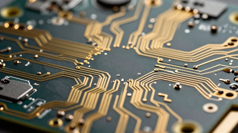
The Architectural Challenges of Micro-Scale Flexibility
The primary hurdle in endoscopic PCB design is the extreme miniaturization required for minimally invasive procedures. Designers must pack sophisticated imaging sensors, LED illumination, and data transmission circuitry into a diameter often less than 3mm. This necessitates the use of ultra-thin, multi-layer flexible circuits that maintain signal integrity while occupying minimal physical volume.
Mechanical Stress and Fatigue Resistance
Unlike standard rigid-flex assemblies in consumer electronics, endoscopic circuits face dynamic, multi-axial bending. Every time a clinician steers the distal tip of an endoscope, the internal flexible circuit experiences localized tension, compression, and shear forces. Standard materials often fail under this repetitive mechanical stress, leading to conductor cracking or insulation delamination. Engineers must prioritize materials with high ductility, such as rolled-annealed copper, over standard electro-deposited copper to ensure longevity across thousands of articulation cycles.
| Constraint | Design Implication | Engineering Strategy |
|---|---|---|
| Spatial Volume | Extreme miniaturization | Multi-layer HDI (High Density Interconnect) stackups |
| Dynamic Bending | Mechanical fatigue | Use of rolled-annealed copper and polyimide films |
| Signal Integrity | EMI/RFI interference | Advanced shielding layers and controlled impedance routing |
Frequently Asked Questions
- Why is standard FR4 material unsuitable for endoscopic probes?
FR4 is a rigid, brittle material that lacks the necessary bend radius and flexibility to navigate the tortuous anatomy of the human body, making it prone to immediate failure in dynamic applications. - How do signal speeds impact PCB material selection?
For high-definition imaging, low-loss dielectric materials are essential to prevent signal attenuation and latency, ensuring high-speed data transmission from the sensor to the external processor. - What is the most critical failure point in a flex circuit?
The most common failure point is the transition zone between the rigid component attachment areas and the flexible segments, where stress concentrations are highest during bending.
Navigating IPC-6013 Standards for Medical Reliability
The Critical Role of IPC-6013 Class 3
For medical endoscope probes, IPC-6013 Class 3 is the mandatory standard for 'high-reliability electronic products.' Unlike consumer-grade electronics, these circuits must maintain continuous operation under extreme mechanical stress and thermal fluctuations without failure. Adherence to Class 3 specifications governs everything from conductor spacing and plating thickness to base material integrity, ensuring the PCB can withstand the rigors of surgical environments and repeated sterilization cycles.
Key IPC-6013 Parameters for High-Definition Reliability
| Requirement | Medical Class 3 Standard | Impact on Endoscope |
|---|---|---|
| Plating Thickness | Uniform 25μm (min) | Prevents barrel cracking during flexing |
| Annular Ring | Strict 0.05mm minimum | Maintains electrical path integrity |
| Dielectric Material | High-Tg Polyimide | Withstands autoclave heat cycles |
FAQs: IPC-6013 Compliance in Medical Manufacturing
- Why is Class 3 better than Class 2 for endoscopes?
Class 3 requires tighter inspection protocols and higher manufacturing tolerances, specifically addressing fatigue resistance and material purity essential for devices inside the human body. - Does IPC-6013 cover sterilization resistance?
While IPC-6013 provides the mechanical framework, it mandates material selection (like high-Tg polyimide) that inherently supports the thermal resistance required for sterilization. - How does IPC-6013 affect micro-circuit miniaturization?
IPC-6013 establishes the minimum feature sizes allowed while maintaining structural safety. Engineers must design to these limits to prevent premature delamination or conductor breakage in tight-diameter probes.
Material Selection: Balancing Biocompatibility and Electrical Performance
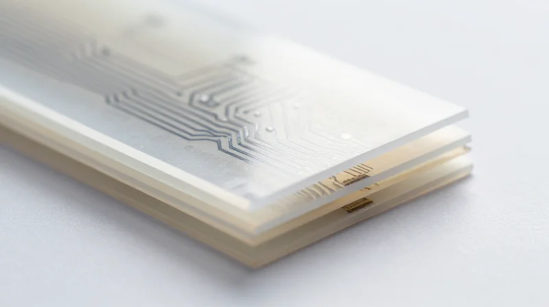
In the development of high-definition medical endoscope probes, the material choice for the flexible substrate acts as the fundamental determinant of both electrical performance and device longevity. Engineers must navigate the trade-off between traditional Polyimide (PI) and emerging Liquid Crystal Polymer (LCP) technologies, particularly concerning moisture ingress and chemical durability in the presence of sterilization agents.
Material Comparison: Polyimide vs. Liquid Crystal Polymer
| Property | Polyimide (PI) | Liquid Crystal Polymer (LCP) |
|---|---|---|
| Moisture Absorption | High (1.5-3.0%) | Extremely Low (<0.04%) |
| Dielectric Constant | 3.2 - 3.5 | 2.9 - 3.0 |
| Chemical Resistance | Moderate | Excellent |
| Thermal Stability | Excellent | High |
Polyimide has long been the industry standard due to its excellent thermal stability and ease of fabrication in multi-layer stack-ups. However, its high moisture absorption rate can lead to impedance instability in high-frequency circuits. Conversely, LCP offers a near-hermetic seal, making it superior for probes subjected to repetitive autoclaving or chemical disinfection cycles, though it requires specialized manufacturing processes due to its lower melting point and high thermoplastic nature.
Frequently Asked Questions
- Why does moisture absorption affect HD image quality?
Moisture absorption changes the dielectric constant of the substrate, which directly alters the impedance of signal traces. In HD imaging, this shift can cause signal reflections, phase distortion, and jitter, leading to degraded image fidelity. - Is LCP always the better choice for medical probes?
While LCP offers superior electrical and moisture-barrier properties, Polyimide is often preferred when complex multi-layer interconnection density or lower manufacturing costs are prioritized, provided the probe is not subjected to extreme moisture environments. - How do these materials interact with sterilization processes?
Chemical sterilants and steam can migrate into the dielectric material. LCP's low porosity effectively prevents chemical accumulation within the PCB core, extending the operational life of the device compared to traditional PI-based circuits.
Prioritizing Signal Integrity in Ultra-Tight Geometries

Achieving Precise Impedance Control in Constrained Spaces
In geometries narrower than 2mm, maintaining the characteristic impedance required for high-speed LVDS or MIPI CSI-2 interfaces becomes exponentially difficult. As trace widths shrink to micron-scale, even minor manufacturing tolerances can lead to significant impedance discontinuities. Engineers must prioritize controlled-impedance designs through exact dielectric thickness management and high-precision laser direct imaging (LDI) to keep signal attenuation within acceptable limits for long-run probe cables.
Mitigating Crosstalk in Micro-Miniature Flex
When signals are packed into a 2mm-wide flexible substrate, electromagnetic interference (EMI) and crosstalk between high-speed data lines and sensitive power rails are inevitable. Mitigation requires a multi-faceted approach, emphasizing physical isolation and electromagnetic shielding.
- Is Differential Pair Routing Essential?
Yes, tight coupling of differential pairs is mandatory to maximize common-mode noise rejection, which is critical in noisy endoscopic environments. - How does shielding impact flexibility?
Using conductive polymers or thin sputtered copper layers provides shielding without adding the bulk or stiffness of traditional metallic foils, preserving the mechanical flexibility of the probe. - Can ground planes be eliminated?
No, a solid reference plane is necessary to prevent return-path issues, which are the primary source of EMI in micro-miniature flexible circuits.
Comparison of Crosstalk Reduction Techniques
| Strategy | Effectiveness | Impact on Flex |
|---|---|---|
| Guard Traces | Moderate | Minimal |
| Layer Separation | High | High (Increases Thickness) |
| Integrated Shielding | Very High | Low |
To ensure reliable performance in clinical settings, designers should utilize 3D electromagnetic field solvers during the pre-layout phase. By simulating the specific stack-up—accounting for the dielectric constants of adhesives and polyimide layers—teams can predict and prevent signal degradation before the costly prototyping stage, ensuring the final probe maintains its high-definition fidelity throughout its operational lifespan.
The Physics of Bend Radius and Flex Fatigue Resistance
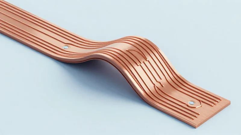
In the confined, articulated anatomy of a medical endoscope, the flexible PCB (FPC) undergoes millions of microscopic strain cycles. The physics of bend radius is governed by the Neutral Axis Theory, where material failure is minimized by placing sensitive copper traces exactly at the center of the substrate's thickness. As miniaturization pushes design limits, managing flex fatigue becomes a function of both geometric placement and material-level metallurgical choices.
Copper Grain Structure: Rolled-Annealed vs. Electro-Deposited
For medical endoscopes, the choice of copper foil is the primary determinant of flex life. Rolled-Annealed (RA) copper is processed to provide a horizontal grain structure, which is inherently more resistant to crack propagation during repeated bending. In contrast, standard Electro-Deposited (ED) copper features a vertical grain structure that is prone to brittle fracturing under dynamic stress.
| Feature | Rolled-Annealed (RA) Copper | Electro-Deposited (ED) Copper |
|---|---|---|
| Grain Structure | Horizontal/Elongated | Vertical/Columnar |
| Flex Fatigue Resistance | High | Low |
| Suitability for Endoscopes | Recommended | Not Recommended |
Optimizing Substrate Thickness and Neutral Axis
The neutral axis represents the layer within the FPC that experiences zero tension or compression during bending. To maximize reliability, designers must balance the thickness of the polyimide base, the adhesive layers, and the copper. By utilizing 'adhesiveless' copper-clad laminates, the total stack-up height is reduced, allowing for a tighter bend radius without increasing strain on the copper traces. Keeping the trace thickness to a minimum further shifts the copper closer to the neutral axis, exponentially increasing the number of cycles to failure.
Frequently Asked Questions on Flex Durability
- How does bend radius correlate with circuit failure?
Smaller bend radii increase the strain on outer copper layers; if the bend radius is tighter than the minimum recommended for a specific material thickness, fatigue-induced micro-cracking occurs prematurely. - Why is adhesiveless construction preferred?
Adhesives add unnecessary thickness and introduce non-uniform mechanical properties, both of which shift the copper away from the neutral axis and reduce overall flex life. - Can trace geometry mitigate fatigue?
Yes, using curved or 'teardrop' trace patterns rather than sharp 90-degree corners reduces stress concentrations, significantly improving performance in high-flex areas.
Thermal Management in Confined Clinical Environments
Thermal Dynamics in Constrained Environments
In the confined distal tip of a high-definition medical endoscope, thermal dissipation is constrained by the lack of airflow and the insulating properties of the surrounding anatomical tissues. As sensor resolution increases, power density rises, potentially causing localized heating that can exceed the 41°C threshold required for safe patient contact. Engineers must utilize the flex PCB as a primary thermal conduit, strategically integrating thermally conductive adhesives and minimizing dielectric thicknesses to bridge the heat generated by CMOS sensors and LED light sources.
Comparative Thermal Conductivity of Substrates
| Material | Thermal Conductivity (W/m·K) | Primary Application |
|---|---|---|
| Polyimide (Standard) | 0.12 - 0.25 | Flexible interconnects |
| Thermally Conductive PI | 0.50 - 1.20 | Sensor mounting areas |
| Liquid Crystal Polymer (LCP) | 0.20 - 0.35 | High-frequency signal paths |
| Copper Foil (1/4 oz) | 385.00 | Heat spreading layers |
Best Practices for Heat Dissipation
Implementing robust thermal management requires a multi-layered design approach that leverages the structural components of the probe itself as a heat sink.
- Can I use ground planes for thermal relief?
Yes, extending internal copper ground planes to act as heat spreaders significantly lowers the junction temperature of imaging sensors, provided the planes do not interfere with high-speed signal integrity. - What is the role of thermal vias in micro-flex?
While traditional vias are large, micro-vias filled with conductive epoxy can act as vertical heat pipes, conducting thermal energy from the component side to the internal layers of the PCB. - How does stack-up design impact heat?
A balanced stack-up with thinner dielectric layers reduces the thermal resistance between the heat source and the outer cover, allowing for more efficient heat transfer to the surrounding environment.
Cleanroom Manufacturing and Contamination Control
For high-definition endoscope probes, the transition from design to clinical deployment relies heavily on contamination control. Micro-flex PCBs operate within the human body, where even microscopic particulate matter or ionic residues can cause short circuits, signal degradation, or, in the worst case, patient adverse events. Maintaining an ISO-classified cleanroom environment—typically ISO Class 7 or higher—is non-negotiable for manufacturers aiming to meet stringent medical device regulations.
Standards and Protocols for Contamination Control
Contamination in micro-electronics is not limited to physical debris; it includes ionic contaminants and organic residues from the fabrication process. Advanced manufacturers employ multi-stage ultrasonic cleaning and deionized water rinses to remove flux residues and etch-back materials that could lead to dendrite growth or localized corrosion over the lifespan of an endoscope.
| Contaminant Type | Clinical Impact | Mitigation Strategy |
|---|---|---|
| Particulates | Potential for shorts or device failure | HEPA filtration & laminar airflow |
| Ionic Residues | Electrochemical migration | Deionized water & plasma cleaning |
| Organic Oils | Poor adhesive/coating bond | Degreasing & surface activation |
Key Considerations for Cleanroom Procurement
- How does ISO classification affect PCB quality?
Lower particle counts in ISO Class 7 or 8 environments minimize the risk of embedded debris that can breach the protective polyimide layers during the final assembly of the endoscope. - Why is plasma cleaning required for medical-grade flex?
Plasma cleaning removes microscopic organic contaminants that are invisible to the naked eye, ensuring that encapsulation materials adhere perfectly to the PCB surface. - What is the role of traceability in contamination control?
Rigorous traceability ensures that every batch of PCBs can be linked back to specific cleanroom logs, verifying that environmental humidity and particle levels were within tolerance during production.
Ultimately, the cleanroom is an extension of the quality management system. When selecting a manufacturing partner, request documentation regarding their contamination control plans, as these are primary indicators of the longevity and safety of the final high-definition imaging probe.
Future-Proofing Your Design with Advanced Substrate Technologies
Next-Generation Substrate Materials
To push past the current limitations of polyimide-based flexible circuits, the industry is transitioning toward advanced liquid crystal polymer (LCP) and fluoropolymer substrates. These materials offer superior moisture resistance, lower dielectric constants, and exceptional dimensional stability, which are critical when designing for the extreme spatial constraints of 1mm-class endoscope heads.
| Material Type | Key Advantage | Clinical Impact |
|---|---|---|
| Modified Polyimide | Improved Adhesion | Reliable high-density routing |
| LCP (Liquid Crystal Polymer) | Near-zero moisture absorption | Long-term stability in fluid |
| Fluoropolymers | Ultra-low dielectric loss | Enhanced high-speed signal integrity |
Additive Manufacturing and Direct Write Technologies
The shift from subtractive etching to additive manufacturing allows for the creation of non-planar circuits directly on complex, curved probe surfaces. Using aerosol jet printing or laser-induced forward transfer, engineers can print conductive traces with resolutions as fine as 5 microns, effectively eliminating the need for traditional laminate bonding processes that contribute to bulky probe assembly.
Frequently Asked Questions on Future-Proofing
- How does LCP improve probe lifespan compared to standard polyimide?
LCP exhibits negligible moisture absorption, preventing the signal degradation and electrochemical migration often seen in polyimide circuits after repeated autoclave cycles. - Can additive electronics replace traditional flex PCBs entirely?
While not a complete replacement yet, additive techniques allow for 'system-in-package' architectures where circuitry is integrated directly into the probe structure, significantly reducing mechanical stress points. - What is the biggest barrier to adopting advanced substrates?
The primary barrier remains the optimization of multi-layer registration during manufacturing, which requires specialized high-precision alignment equipment common in semiconductor foundries.
Choosing the right substrate is the foundation of a successful medical imaging device. By aligning your design choices with stringent IPC standards and material expertise, you can ensure your endoscope performs flawlessly under the most demanding clinical conditions. Are you ready to optimize your next project? Contact our engineering team today for a design consultation.
