
In the world of mission-critical power systems, the failure of a single printed circuit board can lead to catastrophic downtime. Selecting the right manufacturing partner is not just a procurement task; it is an investment in infrastructure reliability. This guide explores the engineering benchmarks and strategic vetting processes required to secure your power supply chain.
Understanding the Demands of Critical Power Infrastructure
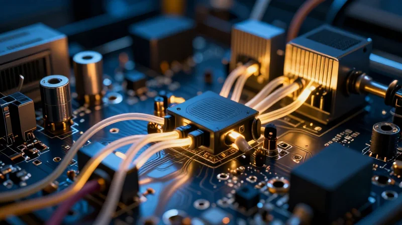
The Engineering Disparity: UPS vs. Standard Electronics
The primary distinction between standard consumer electronics and critical UPS systems lies in the tolerance for failure and the operating environment. While a consumer device may be designed for a short lifecycle with minimal thermal overhead, UPS PCBs must maintain consistent performance under high-current loads, voltage transients, and constant thermal cycling. A manufacturer that handles standard commercial boards may lack the rigorous inspection protocols, specialized substrate materials, and copper weight management necessary for mission-critical power management.
Comparative Requirements for Critical Infrastructure
| Feature | Consumer Electronics | Critical UPS Systems |
|---|---|---|
| Copper Weight | 1 oz standard | 2 oz to 6 oz for heat dissipation |
| Thermal Management | Air-cooled, transient | High-Tg materials, sustained load |
| Inspection | Automated Optical (AOI) | AOI plus X-Ray & Thermal Cycling |
| Expected Life | 2-3 years | 10-15+ years |
Key Challenges in UPS PCB Integrity
- How do thermal fluctuations impact reliability?
Constant expansion and contraction due to thermal cycling can cause fatigue in solder joints and micro-cracks in through-hole vias, leading to intermittent power failures. - Why is copper weight critical for UPS PCBs?
UPS systems often carry high currents that generate significant I2R (resistive) heating; heavier copper traces are mandatory to reduce impedance and prevent trace burnout. - What role does substrate material play?
Critical infrastructure requires high Glass Transition Temperature (Tg) laminates to ensure the PCB maintains structural and electrical integrity even during abnormal power spikes or overheating events.
Selecting a manufacturer for UPS infrastructure requires moving beyond basic production capabilities. Engineers must verify that the fabricator can provide documented evidence of material traceability, IPC Class 3 compliance, and validated thermal management performance data.
The Necessity of IPC Class 3 Standards
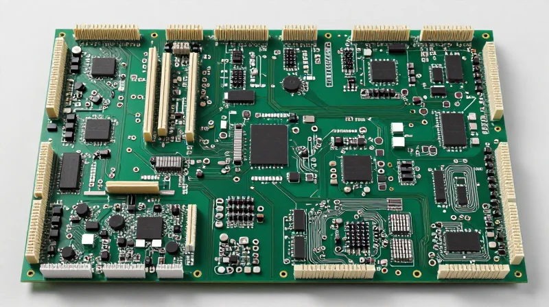
Defining the IPC Class 3 Benchmark
IPC Class 3, or 'High-Performance Electronic Products,' represents the pinnacle of printed circuit board fabrication standards. Unlike Class 1 or Class 2, which are designed for consumer electronics where occasional downtime is a nuisance, Class 3 is engineered for environments where failure is neither acceptable nor safe. In the context of Uninterruptible Power Supply (UPS) systems, these boards must maintain continuous, fault-free performance under extreme thermal cycling and high-current loads.
Class 2 vs. Class 3: Key Differentiators
| Parameter | IPC Class 2 (Standard) | IPC Class 3 (High-Reliability) |
|---|---|---|
| Annular Ring Requirements | Lower tolerance; allows some breakout | Stricter; minimal breakout permitted |
| Drill Registration | Standard precision | High-precision, optimized for thermal stress |
| Plating Thickness | General thickness levels | Increased copper weight/plating for reliability |
| Inspection Criteria | Functional-focused | Enhanced visual and micro-section inspection |
Why IPC Class 3 is Essential for UPS Infrastructure
Critical power systems often operate in uncontrolled environments, such as remote data centers or industrial plants, where thermal expansion and contraction can lead to micro-fractures in solder joints or via barrels. IPC Class 3 mandates more stringent plating requirements and tighter manufacturing tolerances that actively mitigate these fatigue points.
- Does Class 3 increase manufacturing costs?
Yes, it generally commands a higher price due to tighter tolerance requirements, more frequent inspection cycles, and slower production speeds, but this is a necessary investment for critical infrastructure longevity. - What happens if a UPS board fails due to poor quality?
A sub-standard PCB in a UPS can lead to cascading failure, resulting in load drops, physical fire hazards, and massive downtime costs far exceeding the initial PCB savings. - Is Class 3 certification a guarantee of quality?
It is a standard of process control. When selecting a manufacturer, ensure they not only claim IPC Class 3 compliance but have documented quality management systems (like AS9100 or ISO 9001) to support it.
Material Selection and Thermal Management

Laminate Material Selection for High-Thermal Stability
In critical UPS applications, standard FR-4 often falls short. High-reliability manufacturing requires base materials with a high Glass Transition Temperature (Tg) and superior Decomposition Temperature (Td) ratings. These materials prevent delamination and board warping when exposed to continuous high-current cycles and the heat dissipation requirements of power conversion components.
| Material Property | Standard FR-4 | High-Rel/Power Laminate |
|---|---|---|
| Tg (Glass Transition) | 130°C - 140°C | 170°C - 180°C+ |
| Thermal Reliability | Moderate | Exceptional |
| Heat Dissipation | Standard | Enhanced via Fillers |
Copper Weight and Current-Carrying Capacity
The copper weight of a PCB directly dictates the resistance and temperature rise of the conductors. For high-reliability UPS systems, heavy copper (typically 3oz or higher) is essential to reduce ohmic heating. A capable manufacturer must provide tight control over plating thickness and width etching, as inconsistencies here can lead to hotspots and eventual failure under peak load conditions.
Common Considerations for Thermal Management
- How does heavy copper affect thermal performance?
Increased copper cross-sections lower electrical resistance, minimizing heat generation during operation while acting as a structural heat sink for high-power components. - Why is the CTE (Coefficient of Thermal Expansion) important?
Matching the CTE of the laminate to the components reduces mechanical stress on solder joints during temperature cycling, preventing cracking in extreme power environments. - What role does thermal via design play?
Strategic placement of copper-filled thermal vias facilitates the transfer of heat from sensitive power MOSFETs to the inner ground planes or external heat sinks, improving overall system stability.
Assessing Manufacturing Quality Controls

Multi-Stage Inspection Protocols
For critical power infrastructure, relying on final visual inspection is insufficient. A high-reliability manufacturer must integrate non-destructive testing at each phase of the production cycle to detect defects that are invisible to the naked eye, such as internal delamination, micro-cracks, or solder voiding.
| Inspection Technology | Primary Application | Critical Defect Detection |
|---|---|---|
| AOI (Automated Optical) | Surface-level component mounting | Misalignment, bridging, tombstoning |
| AXI (Automated X-Ray) | BGA/QFN solder joints | Internal voids, head-in-pillow, shorts |
| Flying Probe Testing | Bare board functionality | Open circuits, shorts, isolation issues |
Advanced Testing Procedures for UPS Reliability
- Why is AXI (Automated X-Ray Inspection) essential for UPS PCBs?
UPS power boards often utilize heavy copper and bottom-terminated components like BGAs. AXI is the only method to verify solder joint integrity and calculate void ratios within these critical high-current connections. - How does electrical testing validate power distribution?
Beyond simple connectivity tests, high-reliability manufacturers perform Hi-Pot (High Potential) testing and impedance verification to ensure the PCB can withstand the high voltage surges inherent in power systems without arcing. - What role does thermal stress testing play in quality assurance?
By subjecting boards to thermal cycling (rapid temperature transitions), manufacturers can identify potential failure points in vias and trace interconnections that might succumb to thermal expansion fatigue over time.
Ultimately, your manufacturer should provide comprehensive quality reports, including AOI and AXI imagery logs, for every production batch. Transparency in their testing data serves as your primary defense against premature field failures in your power infrastructure.
Supply Chain Transparency and Traceability
The Imperative of Supply Chain Transparency
For critical power systems, a PCB is only as reliable as its source materials and components. Supply chain transparency ensures that every laminate, solder mask, and integrated circuit can be traced back to its origin, effectively eliminating the risk of sub-standard or counterfeit materials entering the assembly process. In high-reliability UPS environments, provenance is the primary defense against systemic failure.
Mitigating Counterfeit Component Risks
The proliferation of counterfeit components in the global market poses a severe threat to UPS infrastructure. Manufacturers must employ rigorous verification protocols, such as COA (Certificate of Analysis) verification and authorized distributor sourcing, to ensure all materials meet strict performance benchmarks.
| Sourcing Strategy | Risk Mitigation Level | Cost/Complexity |
|---|---|---|
| Direct OEM/Authorized Distribution | Highest | High |
| Broad-market Brokerage | Low | Low |
| Certified Material Traceability | Very High | Moderate |
Key Questions for Manufacturers
- How do you verify the authenticity of raw materials?
A high-reliability manufacturer should maintain a documented chain of custody and perform batch-level testing on all incoming raw laminates and chemical components. - What is your policy on component substitution?
Never allow unvetted substitutions. The manufacturer must require client sign-off on any change to the approved vendor list (AVL) to prevent unauthorized part usage. - Can you provide full traceability reports?
They should provide lot-traceability documentation that connects specific PCB serial numbers to the original manufacturing material batches.
Engineering Support and DFM Feedback

The Proactive DFM Advantage
High-reliability UPS systems demand more than standard fabrication capabilities; they require a collaborative engineering partnership where your manufacturer acts as a design safeguard. A proactive Design for Manufacturing (DFM) review evaluates every aspect of your board layout—from signal integrity and impedance control to thermal relief patterns and drill-to-copper clearances. By identifying potential manufacturing constraints during the design phase, manufacturers prevent the propagation of errors that could lead to field failures in mission-critical power environments.
Key DFM Review Parameters for UPS Power Boards
| DFM Focus Area | Impact on UPS Reliability | Common Failure Risk |
|---|---|---|
| Copper Weight/Trace Width | Thermal dissipation and current carrying capacity | Trace fusing or resistive heating |
| Via Integrity | Conductivity in high-current paths | Via barrel cracking under thermal cycling |
| Solder Mask Clearance | Prevents shorts in high-voltage areas | Arcing or voltage breakdown |
| Panelization Efficiency | Uniform plating distribution | Inconsistent copper thickness leading to impedance mismatch |
Strategic Engineering Collaboration
Selecting a manufacturer with dedicated engineering support means gaining access to expert insights on stack-up optimization and material compatibility. Effective engineering support involves real-time feedback loops where manufacturer engineers provide actionable recommendations to align your design with their specific fabrication tolerances, ultimately reducing turn-around time and increasing yields for high-density, multi-layer power boards.
Common DFM Inquiries
- How early should a manufacturer be involved in the design process?
The manufacturer should be involved during the initial design phase to review stack-up and material selection, ensuring the design is optimized for the specific fabrication process. - What constitutes a 'High-Reliability' DFM report?
A high-reliability report goes beyond DRC (Design Rule Check) to analyze thermal management, current density profiles, and potential manufacturing-induced stress points. - Can DFM feedback reduce final assembly costs?
Yes. By optimizing pad sizes and component spacing, manufacturers can improve automated assembly yields and reduce the need for manual rework.
Facility Audits and Certification Verification
Structuring the Facility Audit
A rigorous facility audit is the ultimate verification of a manufacturer's operational maturity. Whether conducted on-site or remotely, the objective is to move beyond marketing brochures to observe the actual execution of process controls, environmental standards, and quality management systems (QMS).
- ISO Certification Validity
Do not just accept a PDF copy of an ISO 9001 or IATF 16949 certificate. Verify the registration number against the registrar's official database to ensure the scope of certification covers the specific manufacturing lines producing your high-reliability PCBs. - Environmental Control Verification
For power-dense UPS boards, humidity and temperature control are vital. Request historical logs from cleanroom monitoring systems to ensure consistency during sensitive lamination and etching stages. - Process Flow Mapping
Request an end-to-end process map. Compare this against their actual production floor layout to ensure there are no bottlenecks or areas where cross-contamination of materials could occur.
Certification and Compliance Comparison
| Certification | Significance for UPS PCBs | Verification Method |
|---|---|---|
| ISO 9001 | Baseline quality management | Database audit |
| IPC-A-600 | Acceptability of printed boards | Review of internal training records |
| UL 796 | Safety requirements for printed boards | UL Online Certifications Directory |
| IATF 16949 | Advanced automotive quality standards | On-site audit of failure analysis logs |
Verifying Claims via Technical Evidence
When assessing a manufacturer's capabilities, demand objective evidence rather than qualitative assertions. For UPS infrastructure, the manufacturer must demonstrate a 'Closed-Loop' corrective action system. During your audit, request a 'Case Study' of a recent production reject; the manufacturer should be able to produce the Non-Conformance Report (NCR), the Root Cause Analysis (RCA), and the subsequent process change notice that prevented recurrence.
Managing Long-Term Supplier Partnerships
Transitioning from Procurement to Strategic Partnership
In the context of critical power systems, viewing a PCB manufacturer merely as a commodity vendor is a strategic risk. A collaborative long-term partnership shifts the focus from bottom-line unit pricing to total cost of ownership (TCO) and risk mitigation. By integrating the manufacturer into your product lifecycle strategy, you leverage their specialized manufacturing expertise to improve reliability, accelerate time-to-market, and proactively navigate supply chain volatility.
Key Performance Metrics for Long-Term Alignment
| Metric Category | Transactional Focus | Strategic Partnership Focus |
|---|---|---|
| Cost Basis | Unit Price Optimization | Total Cost of Ownership (TCO) |
| Communication | Reactive Escalation | Proactive Quarterly Reviews |
| Reliability | Standard Quality Compliance | Continuous Yield Improvement |
| Inventory | Just-in-Time Delivery | Strategic Buffer Stock Management |
Fostering Continuous Improvement
High-reliability manufacturers demonstrate their value through continuous improvement initiatives. A mature partnership involves regular deep-dive sessions regarding production yield data, root cause analysis of historical defects, and collaborative roadmapping for component longevity. This ensures that as your UPS system evolves, the PCB manufacturing process remains optimized for reliability rather than just cost.
- How often should formal business reviews occur?
Quarterly business reviews are standard for high-criticality sectors to discuss performance, emerging supply chain risks, and upcoming technological shifts in PCB design requirements. - What role does shared data play in long-term success?
Sharing your field failure data and long-term demand forecasts allows the manufacturer to implement better testing protocols and secure hard-to-source raw materials in advance. - Why is mutual transparency vital for UPS infrastructure?
Transparency creates a 'no-surprises' environment. When a manufacturer feels like a partner, they will proactively alert you to potential material obsolescence or production bottlenecks before they impact your delivery schedules.
Selecting a PCB manufacturer for UPS infrastructure requires a rigorous focus on quality standards and supply chain integrity. By prioritizing IPC Class 3 compliance and deep technical transparency, you protect your systems against failure. Contact our engineering team today to discuss your next mission-critical project requirements.
